Logo 30.3009.54.IT - Thermometer TFA - Free user manual and instructions
Find the device manual for free Logo 30.3009.54.IT TFA in PDF.
| Product type | Wireless weather station with indoor/outdoor thermometer |
| Brand | TFA |
| Model | Logo 30.3009.54.IT |
| Display | LCD with time, indoor and outdoor temperatures |
| Time formats | 12 h or 24 h (selectable) |
| Temperature units | °C or °F (automatic based on time format) |
| Indoor temperature range | -9.9 °C to +59.9 °C (14.2 °F to 139.8 °F) |
| Outdoor temperature range | -39.9 °C to +59.9 °C (-39.8 °F to +139.8 °F) |
| Resolution | 0.1 °C / 0.2 °F |
| Min/max memory | Yes, with button reset |
| Number of supported transmitters | Up to 3 |
| Transmission frequency | 868 MHz |
| Transmission range | Up to 100 m in open field |
| Indoor measuring interval | 15 seconds |
| Outdoor measuring interval | 4 seconds |
| Station power supply | 2 AA 1.5 V batteries (LR6) |
| Transmitter power supply | 2 AA 1.5 V batteries (LR6) |
| Battery life | Approximately 24 months (alkaline recommended) |
| Station dimensions (WxHxD) | 60 x 31 x 157 mm (without stand) |
| Transmitter dimensions (WxHxD) | 38.2 x 21.2 x 128.3 mm (without bracket) |
| Mounting | Wall or table mount (removable bracket) |
| Transmitter protection rating | Splash resistant (not waterproof) |
| Cleaning | Soft damp cloth, no solvents |
| Safety | Keep out of reach of children; do not open; batteries: do not mix types or old/new |
Frequently Asked Questions - Logo 30.3009.54.IT TFA
User questions about Logo 30.3009.54.IT TFA
0 question about this device. Answer the ones you know or ask your own.
Ask a new question about this device
Download the instructions for your Thermometer in PDF format for free! Find your manual Logo 30.3009.54.IT - TFA and take your electronic device back in hand. On this page are published all the documents necessary for the use of your device. Logo 30.3009.54.IT by TFA.
USER MANUAL Logo 30.3009.54.IT TFA
natural_image
Diagram of a vertical spring scale and a multi-tiered server rack (no text or symbols)natural_image
Diagram of a battery with internal compartments and an external casing (no text or symbols)natural_image
Technical line drawing of a mechanical device with internal components and mounting base (no text or symbols)natural_image
Two vertical scientific apparatus diagrams, one with a thermometer and the other a multi-tiered rack (no text or symbols)text_image
Two identical crossed-out recycling symbols, indicating no waste or non-renewable disposal.Thank you for choosing this wireless temperature station from TFA.
BEFORE YOU USE IT
Please be sure to read the instruction manual carefully.
This information will help you to familiarise yourself with your new device, learn all of its functions and parts, find out important details about its first use and how to operate it, and get advice in the event of faults.
Following the instruction manual for use will prevent damage to the device and loss of your statutory rights arising from defects due to incorrect use.
We shall not be liable for any damage occurring as a result of not following these instructions.
Please take particular note of the safety advice!
Please look after this manual for future reference.
SCOPE OF SUPPLY:
• Temperature station (basic unit)
• Outdoor transmitter
- Instruction manual
FIELD OF OPERATION AND ALL OF THE BENEFITS OF YOUR NEW TEMPERATURE STATION AT A GLANCE:
• LCD clock in 12 or 24 hour time display
- Indoor and outdoor temperature reading in degree Celsius (°C) or degree Fahrenheit (°F)
- Can receive up to three outdoor transmitters
- Indoor and outdoor temperature with minimum and maximum records
• Wireless transmission at 868 MHz
• Signal reception intervals at 4 seconds
- Table standing or wall mountable (detachable table stand)
FOR YOUR SAFETY:
- The product is exclusively intended for the field of application described above. The product should only be used as described within these instructions.
- Unauthorised repairs, modifications or changes to the product are prohibited.

Caution! Risk of injury:
- Keep this instrument and the batteries out of reach of children.
- Batteries must not be thrown into the fire, short-circuited, taken apart or recharged. Risk of explosion!
- Batteries contain harmful acids. Low batteries should be changed as soon as possible to prevent damage caused by a leaking battery. Never use a combination of old and new batteries together or
batteries of different types. Wear chemical-resistant protective gloves and glasses when handling leaked batteries.
! Important information on product safety!
- Do not expose the instrument to extreme temperatures, vibration or shock.
- Protect from moisture.
- The outdoor transmitter is protected against splash water, but is not watertight. Choose a shady and dry position for the transmitter.
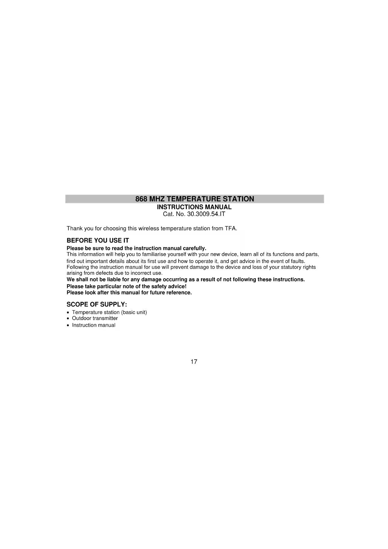
ELEMENTS
The temperature station:
text_image
ELEMENTS The temperature station: SET/CHANNEL key RESET+/MIN/MAX key Hanging hole Detachable standThe outdoor transmitter:
natural_image
Technical line drawing of a vertical mechanical device and a server rack (no text or symbols)- Remote transmission of outdoor temperature to temperature station by 868 MHz signal
- Wall mounting case
- Mounting at a sheltered place. Avoid direct rain and sunshine
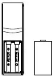
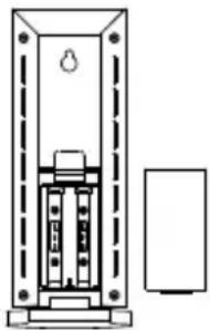
HOW TO INSTALL AND REPLACE BATTERIES IN THE TEMPERATURE TRANSMITTER
natural_image
Diagram of a battery cell with internal components and external casing (no text or symbols)The temperature transmitter uses 2 x AA, IEC LR6, 1.5V batteries. To install and replace the batteries, please follow the steps below:
- Slide the battery cover downwards and remove.
- Insert the batteries, observing the correct polarity (see marking).
- Replace the battery cover.
HOW TO INSTALL AND REPLACE BATTERIES IN THE TEMPERATURE STATION
natural_image
Technical line drawing of a mechanical device with no visible text or symbolsThe temperature station uses 2 x AA, IEC LR6, 1.5V batteries. To install and replace the batteries, please follow the steps below:
- Insert finger or other solid object in the space at the bottom center of the battery compartment and lift up to remove the cover.
- Insert batteries observing the correct polarity (see marking).
- Replace compartment cover.
Note:
In the event of changing batteries in any of the units, all units need to be reset by following the setting up procedures. This is because a random security code is assigned by the transmitter at start-up and this code must be received and stored by the temperature station in the first three minutes of power being supplied to it.
SETTING UP:
WHEN ONE TRANSMITTER IS USED
- First, insert the batteries in the transmitter (see "How to install and replace batteries in the temperature transmitter" above).
-
Within 2 minutes of powering up the transmitter, insert the batteries in the temperature station (see "How to install and replace batteries in the temperature station" above). Once the batteries are in place, all segments of the LCD will light up briefly. Following the indoor temperature and the time as 0:00 will be displayed. If this information is not displayed on the LCD after 60 seconds, remove the batteries and wait for at least 60 seconds before reinserting them. Once the indoor data is displayed the user may proceed to the next step.
-
After the batteries are inserted, the temperature station will start receiving data signal from the transmitter. The outdoor temperature data should then be displayed on the temperature station. If this does not happen after 2 minutes, the batteries will need to be removed from both units and reset from step 1.
- In order to ensure sufficient 868 MHz transmission however, the distance between the temperature station and the transmitter should not be more than 100 meters (see notes on "Positioning" and "868 MHz Reception").
Note:
In the event of changing batteries of the units, ensure the batteries do not spring free from the contacts. Always wait at least 1 minute after removing the batteries before reinserting, otherwise start up and transmission problems may occur.
WHEN MORE THAN ONE TRANSMITTER IS USED
- Remove all the batteries from the temperature station and transmitters, and wait 60 seconds.
- Insert the batteries in the first transmitter.
- Within 2 minutes of powering up the first transmitter, insert the batteries in the temperature station. Once the batteries are in place, all segments of the LCD will light up briefly. Following the indoor temperature and the time as 0:00 will be displayed. If this information is not displayed on the LCD after 60 seconds, remove the batteries from both units and wait for at least 60 seconds before reinserting them.
- The outdoor temperature data from the first transmitter (channel 1) should then be displayed on the temperature station. Also, the signal reception icon will be displayed. If this does not happen after 2 minutes, the batteries will need to be removed from both units and reset from step 1.
- Insert the batteries in the second transmitter as soon as the outdoor temperature readings from the first transmitter are displayed on the temperature station.
Note : Insert the batteries into the second transmitter within 45 seconds after the temperature station displays the information of the first transmitter.
- The outdoor temperature from the second transmitter and the "channel 2" icon should then be displayed on the temperature station. If this does not happen after 2 minutes, the batteries will need to be removed from all the units and reset from step 1.
- Insert the batteries in the third transmitter as soon as the "channel 2" icon and outdoor data are displayed on the temperature station. Then within 2 minutes, the channel 3 outdoor data from the third transmitter will be displayed and the channel icon will shift back to "1" once the third transmitter is successfully received. If this does not happen, restart the setting up from step 1.
Note : Insert the batteries into the third transmitter within 45 seconds after the temperature station displays the information of the first transmitter or immediately after reception of the second transmitter is finished.
- In order to ensure sufficient 868 MHz transmission however, the distance between the temperature station and the transmitter should not be more than 100 meters (see notes on "Positioning" and "868 MHz Reception").
IMPORTANT:
Transmission problems will arise if the setting for additional sensors is not followed as described above. Should transmission problems occur, it is necessary to remove the batteries from all units and start again the set-up from step 1.
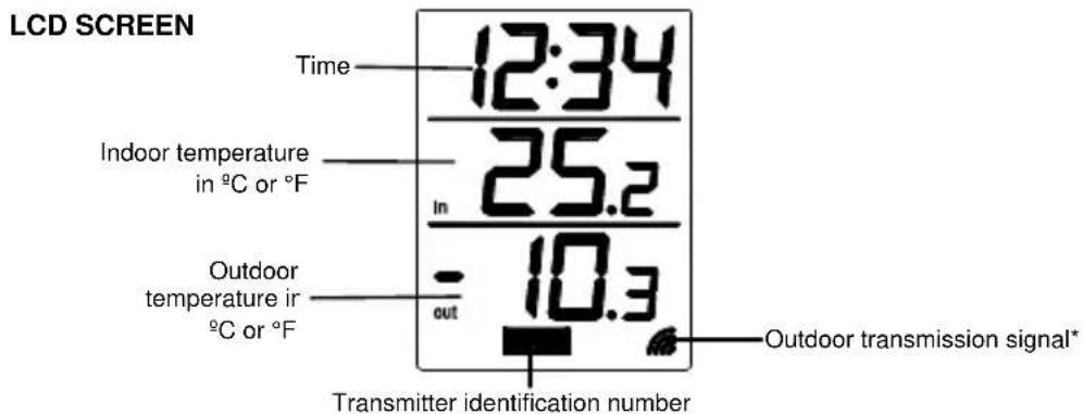
text_image
LCD SCREEN Time 12:34 Indoor temperature in °C or °F 25.2 In Outdoor temperature in °C or °F out 10.3 Transmitter identification number Outdoor transmission signal* ** When the signal is successfully received by the temperature station, the outdoor transmission icon will be switched on. (If not successful, the icon will not be shown on LCD). The user can then easily see whether the last reception was successful (icon on) or not (icon off). On the other hand, the short blinking of the icon shows that a reception is currently taking place.
12 OR 24 HOUR SETTING:
After the batteries are inserted, set the time display as follows:
- Press and hold the "SET/CHANNEL" button about 3 seconds to enter the set mode.
-
Either a “: 12h” or “: 24h” will appear on the LCD. If “: 12h” is displayed then the current time display is set to 12-hour time. If “: 24h” is displayed then the current time is set to 24-hour time.
-
To alternate between the two times display mode, simply press the "RESET/+/MIN/MAX" button.
- When the desired time display is selected, press the "SET/CHANNEL" button once more to enter the Time setting mode.
Note: When the time display is set as 12-hour mode, the temperature unit will be set to °F; when the time mode is in 24-hour format, the temperature unit will be set to °C.
TIME SETTING:
Following from the 12 or 24 hour setting mode.
-
The hour digit in the time section starts flashing
-
Using the "RESET/+/MIN/MAX" button, enter the hours of the current time and then followed by pressing the "SET/CHANNEL" button to move into the minutes mode
- Again, using the "RESET/+/MIN/MAX" button, enter the minutes of the current time (by holding the button down, the digits are incremented in steps of five) and then finally followed by pressing the "SET/CHANNEL" button to exit the setting mode. Your temperature Station is now fully operational.
MINIMUM AND MAXIMUM INDOOR AND OUTDOOR TEMPERATURE READING:
By pressing the "RESET/+/MIN/MAX" button the current indoor and outdoor temperature will alternate between the minimum, maximum and current temperature recordings. Once a new indoor and/or outdoor temperature high or is low reached, it will automatically be set into the temperature station's memory.
RESETTING THE MINIMUM AND MAXIMUM TEMPERATURE RECORDING:
By pressing and holding down the "RESET/+/MIN/MAX" button for about 3 seconds, both the indoor and outdoor minimum and maximum temperature recordings will be reset to the current indoor and outdoor temperatures. Only the outdoor temperature of the displayed transmitter will be reset. To reset the outdoor temperature of another transmitter move to the desired channel number.
OUTDOOR TEMPERATURE 1, 2, AND 3
If more than one transmitter is being used, to alternate between the temperature readings of transmitter 1, 2, and 3, simply press the "SET/CHANNEL" button. If the reading is from transmitter 1, then the identification numbers 1 will be displayed in the outdoor temperature section of the LCD. The same will apply to the next transmitter and so on. However, if only one transmitter is used, no identification number will be displayed on the LCD.
TEMPERATURE TRANSMITTER
The outdoor temperature is measured and transmitted every 4 seconds.
The range of the temperature transmitter may be affected by the temperature. At cold temperatures the transmitting distance may be decreased. Please bear this in mind when placing the transmitter.
868 MHz RECEPTION:
If the outdoor temperature data is not being received within three minutes after setting up (or outdoor display always show “- - . -” in the outdoor section of the temperature station during normal operation), please check the following points:
- The distance of the temperature station or transmitter should be at least 1.5 to 2 meters away from any interfering sources such as computer monitors or TV sets.
- Avoid placing the receiver onto or in the immediate proximity of metal window frames.
- Using other electrical products such as headphones or speakers operating on the same signal frequency (868MHz) may prevent correct signal transmission and reception.
- Neighbors using electrical devices operating on the 868 MHz signal frequency can also cause interference.
Note:
When the 868MHz signal is received correctly, do not re-open the battery covers of either the transmitter or temperature station, as the batteries may spring free from the contacts and force a false reset. Should this happen accidentally then reset all units (see Setting up above) otherwise transmission problems may occur.
The transmission range is about 100 m from the transmitter to the temperature station (in open space). However, this depends on the surrounding environment and interference levels. If no reception is possible despite the observation of these factors, all system units have to be reset (see Setting up).
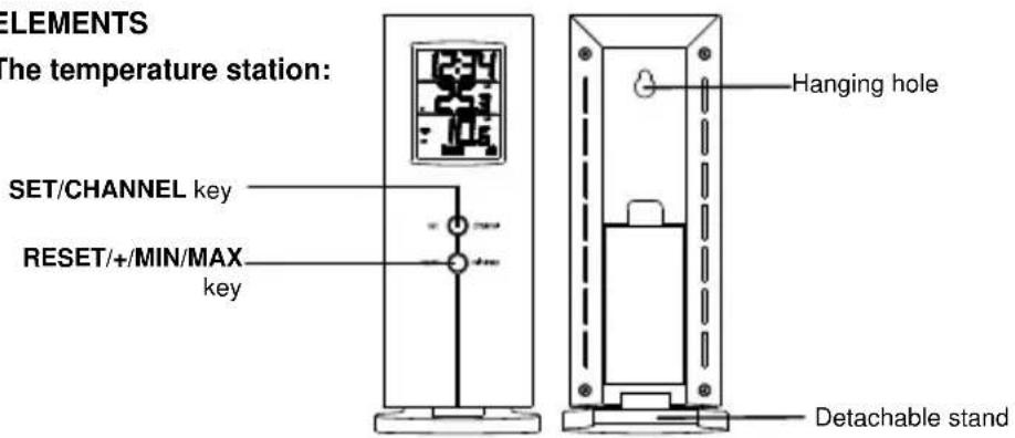
POSITIONING THE TEMPERATURE STATION:
The temperature station has been designed for hanging on a wall or free standing.
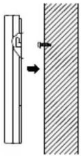
natural_image
Diagram showing a mechanical component interacting with a shaded surface, no text or symbols presentTo wall mount
Before wall mounting, please check that the outdoor temperature values can be received from the desired locations. To wall mount:
-
Fix a screw (not supplied) into the desired wall, leaving the head extended out the by about 5mm.
-
Remove the stand of the temperature station by pushing inward and hang it onto the screw. Remember to ensure that it locks into place before releasing.
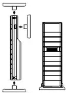
POSITIONING THE OUTDOOR TEMPERATURE TRANSMITTER:
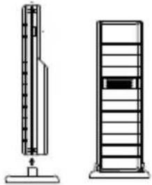
natural_image
Two technical line drawings of vertical structures: a tall tower with internal components and a multi-tiered tower with horizontal bars (no text or symbols)The sensor is supplied with a holder that may be attached to a wall with the two screws supplied.
The transmitter can also be position on a flat surface by securing the stand to the bottom of the transmitter.
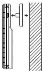
natural_image
Technical diagram showing a mechanical assembly with a vertical component and a side view (no text or symbols)To wall mount:
- Mark the wall using a pen through the holes in the holder to obtain the exact drilling position.
- Drill holes in the wall at the points marked.
- Screw holder onto wall.
Note:
Before permanently fixing the transmitter wall base, place all units in the desired locations to check that the outdoor readings are receivable. In event that the signal is not received, relocate the transmitter(s) or move them slightly as this may help the signal reception.
The transmitter simply clicks in or out of the holder. When inserting or removing the transmitter from the wall holder please hold both units securely.
CARE AND MAINTENANCE
- Clean the instrument and the transmitter with a soft damp cloth. Do not use solvents or scouring agents. Protect from moisture.
- Remove the batteries if you do not use the product for a lengthy period.
MALFUNCTION
| Problems | Troubleshooting |
| No indication on the temperature station | Ensure batteries polarity are correctChange batteries |
| No transmitter receptionDisplay "---" | Check batteries of external transmitter (do not use rechargeable batteries!)Restart the transmitter and temperature station as per the manualChoose another place for the transmitter and/or the temperature stationReduce the distance between the transmitter and the temperature stationCheck if there is any source of interference |
| Incorrect display | Change batteries |
WASTE DISPOSAL
This product has been manufactured using high-grade materials and components which can be recycled and reused.
text_image
Two identical diagrams showing a waste bin with crossed-out lines and a blank rectangular area below, indicating no waste or no disposal.Never throw flat batteries and rechargeable batteries in household waste.
As a consumer, you are legally required to take them to your retail store or to appropriate collection sites according to national or local regulations in order to protect the environment.
The symbols for the heavy metals contained are: Cd=cadmium, Hg=mercury, Pb=lead
This instrument is labelled in accordance with the EU Waste Electrical and Electronic Equipment Directive (WEEE).
Please do not dispose of this product with other household waste. The user is obligated to take end-of-life devices to a designated collection point for the disposal of electrical and electronic equipment, in order to ensure environmentally-compatible disposal.
SPECIFICATIONS:
Temperature measuring range:
Indoor : -9.9°C to +59.9°C with 0.1°C resolution / 14.2°F to 139.8°F with 0.2°F resolution (“--,” displayed if outside this range)
Outdoor : -39.9°C to +59.9°C with 0.1°C resolution / -39.8°F to +139.8°F with 0.2°F resolution (“--.-” displayed if outside this range)
Data checking intervals:
Indoor Temperature : Every 15 seconds
Outdoor temperature data checking interval: Every 4 seconds (or every 15 minutes if data are lost and display “--.-”)
Transmission range : up to 100 meters (open space)
Transmission frequency : 868 MHz
Maximum radio-frequency power : < 25mW
Power consumption
Temperature station : 2 x AA, IEC LR6, 1.5V batteries
Transmitter : 2 x AA, IEC LR6 1.5V batteries
Battery life for both units : Approximately 24 months (Alkaline batteries recommended)
Dimensions (L x W x H):
Temperature station : 60 x 31 x 157 mm (table stand excluded)
Transmitter : 38.2 x 21.2 x 128.3 mm (wall bracket excluded)
No part of this manual may be reproduced without written consent of TFA Dostmann. The technical data are correct at the time of going to print and may change without prior notice.
The latest technical data and information about your product can be found by entering your product number on our homepage.
EU declaration of conformity
Hereby, TFA Dostmann declares that the radio equipment type 30.3009.54.IT is in compliance with Directive 2014/53/EU.
The full text of the EU declaration of conformity is available at the following internet address:
www.tfa-dostmann.de
MANUEL D'INSTRUCTIONS
Cat. No. 30.3009.54.IT