
30.3150 - Thermometer TFA - Free user manual and instructions
Find the device manual for free 30.3150 TFA in PDF.


| Product Type | Professional Weather Center |
| Brand | TFA |
| Model | 30.3150 |
| Main Unit Dimensions | 185.8 x 136.9 x 32 mm |
| Thermo-Hygro Sensor Dimensions | 55.5 x 101 x 24 mm |
| Anemometer Dimensions | 405 x 375 x 160 mm |
| Rain Gauge Dimensions | 163 x 177 x 119 mm |
| Main Unit Weight (without batteries) | 231 g |
| Thermo-Hygro Sensor Weight (without batteries) | 65 g |
| Anemometer Weight (without batteries) | 315 g |
| Rain Gauge Weight (without batteries) | 290 g |
| Power Supply Main Unit | 4 x AA 1.5V batteries |
| Power Supply Remote Sensors | 2 x AA 1.5V batteries each |
| RF Frequency | 434 MHz |
| Transmission Range (open area) | Up to 100 m |
| Number of Supported Thermo-Hygro Sensors | Up to 5 channels |
| Barometric Pressure Range | 500 to 1100 hPa |
| Outdoor Temperature Range | -40°C to 80°C |
| Indoor Temperature Range | -9.9°C to 60°C |
| Humidity Range | 0% to 99% |
| Wind Speed Range | 0 to 199.9 mph |
| Rainfall Measurement (1h/24h/yesterday) | 0 to 1999.9 mm |
| Clock System | Radio-controlled atomic clock (DCF-77) |
| PC Connection | USB cable and CD-ROM included |
| Cleaning Instructions | Use damp cloth; do not use abrasive cleaners or solvents |
Frequently Asked Questions - 30.3150 TFA
User questions about 30.3150 TFA
0 question about this device. Answer the ones you know or ask your own.
Ask a new question about this device
Download the instructions for your Thermometer in PDF format for free! Find your manual 30.3150 - TFA and take your electronic device back in hand. On this page are published all the documents necessary for the use of your device. 30.3150 by TFA.
USER MANUAL 30.3150 TFA
Professional Weather Center

USER'S MANUAL
Introduction
Congratulations on your purchase of the “SINUS” WEATHER STATION. The weather station consists of a main console unit, as well as an assortment of remote sensors which collect and transmit a wide range of weather data, including outdoor temperature, humidity, wind speed, wind direction and rain amount.
The main console unit stores around 200 weather records without a computer connection. When linked to a computer using the USB cable and software provided, an unlimited number of weather records can be displayed and saved onto the computer.
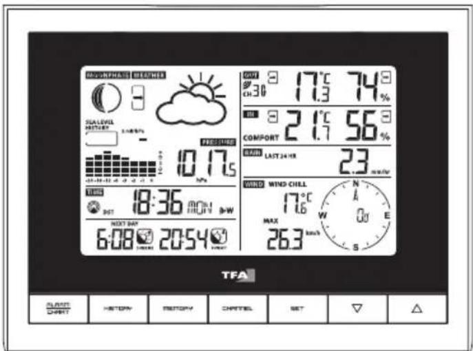
Main Console Unit
The main console unit features a radio-controlled atomic precision clock with alarm and weather forecast. It measures indoor temperature and humidity, and displays weather data collected by the remote weather sensors. It also provides indication of the indoor/outdoor temperature, pressure and humidity trends, and celestial information such as moon phase, and sunrise/set times.
Remote Weather Sensors
The remote weather sensors include a thermo-hygrometer, anemometer (wind sensor) and rain sensor. All data collected by the sensors is transmitted to the main console unit by wireless RF, with a range up to 100 meters (open area). The weather station supports a maximum of 5 thermohygrometers, allowing 5 channels of temperature/humidity display.
Contents of Complete Weather Station Kit
Before installing your weather station, please check that the following are complete:
| Hardware Components | Fittings / Mounting material | |
 | Main Console Unit | |
 | Thermo-Hygro Sensor | |
 | Rain Sensor:- Funnel shaped Lid with Battery Hatch- Sensor Base- Bucket See-saw Mechanism- Protective Screen | 4 screws for securing unit to ground |
 | Anemometer (Wind Sensor):-Wind Cups- Wind Vane- Anemometer arm- Anemometer base | 4 screws for securing unit Mounting material |
 | -CD-ROM-Cable for the base computer link | 2 m (6 ft) |
Installing your weather station
Setting up the Remote Weather Sensors
Before starting up the main console unit, setup all the remote sensors first.
When placing the sensors, make sure that they are within receiving range of the console unit. Ideally they should be within the line of sight of the console unit. Transmission range may be affected by trees, metal structures and electronic appliances. Test reception before permanently mounting your weather station.
Also make sure that the sensors are easily accessible for cleaning and maintenance.
The remote sensors should be cleaned on a weekly basis, since dirt and debris will affect sensor accuracy.
Setting up the Thermo-Hygro Sensor(s)
- Open the latch at the base of the thermo-hygro sensor.
- Set the channel with a slide switch.
- Insert two 2 x UM-3 or "AA" size 1.5V batteries.
- Use a pin to press the RESET key which is in the battery compartment of thermo-hygro Sensors.
- Replace the latch and mount unit at desired location.
Placement tips:
- The thermo-hygro sensor should be in an area with free air circulation and sheltered from direct sunlight and other extreme weather conditions. Place the unit in a shaded area, such as under a roof.
- Avoid placing the sensor near sources of heat such as chimneys.
- Avoid any areas which collect and radiate heat in the sun, such as metal, brick or concrete structures, paving, patios and decks.
- Ideally, place the sensor above natural surfaces such as a grassy lawn.
- The international standard height for measurements of air temperature is at 1.25m (4 ft) above ground level.
Setting up the Rain Sensor
- Unlock the funnel-shaped top of the rain sensor by turning both knobs on the sides of the rain sensor in an anti-clockwise direction.
- Lift the top off the base and insert two 2 x UM-3 or "AA" size 1.5V batteries into the battery holder.
- Remove the adhesive tape from the see-saw.
- Replace the lid and secure into place by turning the knobs clockwise.
- Place the rain sensor in a location such that precipitation can fall directly into the sensor, ideally (2-3 ft) 1m above the ground.
- It may be secured into place by using the four screws provided.
- The sensor must be accurately level for optimum performance. To check if the sensor is level, remove the lid and check if the ball bearing inside is at the midpoint of the leveler. Additionally, a bubble level or carpenter's level may be used.
- Attach the protective screen onto the top of the lid. The screen will prevent any debris entering the sensor.
Placement tips:
- The rain sensor should be placed in an open area away from walls, fences, trees and other coverings which may either reduce the amount of rainfall into the sensor, deflect the entry of wind-blown rain, or create extra precipitation runoff. Trees and rooftops may also be sources of pollen and debris.
- To avoid rain shadow effects, place the sensor at a horizontal distance corresponding to two to four times the height of any nearby obstruction.
- It is important that rain excess can flow freely away from the sensor. Make sure that water does not collect at the base of the unit.
- The rainfall measurement mechanism utilizes a magnet, hence do not place any magnetic objects around the proximity of the sensor.
Setting up the Anemometer (wind sensor)
- Plug the wind wheel on the pin at the bottom of the anemometer. Please note the shape of the pin. With the enclosed Allen wrench tool tighten the screw through the screw hole.
- Open the battery compartment (screwed) and insert the enclosed batteries 2 x 1,5 V AA or remove the insulation stripe. Observe the correct polarity.
- Mount the bracket by using the enclosed mounting material preferably at a mast or on a vertical surface.
- To ensure that the main console unit can display the correct wind direction, the wind vane has to be oriented with its head to the north, while the complete wind vane is in line with the anemometer's arm (fin is in line with the anemometer's arm, tip shows to the other direction). Use a compass if necessary.
Note: If it is not possible to place the anemometer's arm to the north as provided by default, the wind direction has to be adjusted manually.
I. Observe the correct polarity of the batteries.
II. Point the wind vane towards the north. If necessary use a compass for a precise input.
III. Use a pin to press the SET key which is in the battery compartment of the wind sensor.
Attention: Above procedure must be repeated when changing batteries.
Placement tips:
- Check that wind can travel freely around the anemometer and is not distorted by nearby buildings, trees or other structures.
- The official mounting location for anemometers is 10m (33 ft) above ground level in a clear unobstructed location.
Setting up the Main Console Unit
- Open the latch at the back of the main console unit.
- Insert 4 x UM-3 or "AA" size 1.5V batteries according to the polarities shown.
- Reattach the latch.
- If placing the console unit on a table or horizontal surface mount the enclosed table stand.
- If mounting the console unit on a wall or vertical surface, use the fitting provided.
Placement tips:
Make sure that the console unit is within receiving range of all remote sensors. Ideally sensors should be within the line of sight of the console unit. Transmission range may be affected by trees, metal structures and electronic appliances. Test reception before permanently mounting your weather station.
The console unit measures indoor temperature, humidity, pressure and receives signals from all remote sensors and radio-clock broadcasts. Avoid placing the console unit in the following areas:
- Direct sunlight and surfaces which radiate and emit heat.
- Near heating and ventilation devices, such as heating ducts or air conditioners.
- Areas with interference from wireless devices (such as cordless phones, radio headsets, baby listening devices) and electronic appliances.
Starting up the Main Console Unit
Once the console unit is properly powered, the display will start showing some data and weather parameters. Wait for a few minutes for the console to finish self-calibration and for the sensor readings to show up.
If “---” is still displayed for the sensor reading(s), check the wireless transmission path and the batteries for the corresponding sensor.
Using your Weather Station


natural_image
Technical line drawing of a mechanical device with no visible text or symbolsALARM/CHART - Shows time alarms and alerts for temperature, rain and wind.
- Press and hold to enter alarm/alert setup
- Press and hold in Pressure and Weather Forecast Mode to view different bar-charts
HISTORY - Shows history for sea-level pressure
MEMORY - Shows records for moon phase, temperature, humidity, rain and wind.
CHANNEL - Changes temperature and humidity display to selected channel
- Press and hold to enable cycling display of channel temperature and humidity
SET - Rotates display for current mode
- Press and hold to enter setup or change units
- Confirmation for setting parameters
▼ DOWN - Switches to next mode in clockwise direction
- Decrement for setting parameters
▲ UP - Switches to next mode in anti-clockwise direction
- Increment for setting parameters
LIGHT/SNOOZE - Enters Snooze mode when alarm is activated
- Press to activate backlight for 5 seconds.
Display
Section I
Weather Forecast
- Sunny, Partly Cloudy, Cloudy, Slight Rain, Heavy Rain, Snow and Unstable Weather conditions
Pressure
- Current or historical pressure (mBar/ hPa, mmHg or inHg)
- Altitude or sea level pressure adjustment for atmospheric pressure compensation
- Pressure trend indication
- Sea-level pressure history for the last 24 hours
- Sea-level pressure history bar chart
Moon phase
- 12 steps of moon symbols
- Scans moon phase for year 2000 to 2099
- Moon phase history for the last or future 39 days
Section II
Radio Controlled Clock
- Time and date synchronized by radio signal DCF-77 to atomic clock precision (time and date also manually adjustable)
Clock and Calendar (12hr/ 24 hr) (month/day or day/month)
- Different combinations of clock and calendar displays
- 6 languages for day of week (English/ German/ French/ Italian/ Spanish/ Dutch)
Alarms
- Single alarm: activated once at specified time
- Weekday alarm: activated everyday from Monday to Friday at specified time
- Pre-alarm: activated ahead of single or weekday alarm if channel 1 temperature falling to +2°C or below. (Fixed 30 minutes)
- Programmable snooze function (1-15 minutes)
Section III
Sunrise time and sunset time
- Calculates sunrise/set times with geographical information provided by user (DST, zone time offset, latitude, longitude)
- over 133 preset cities can be selected for automatic geographical information input
Section IV
Temperature and relative humidity, with trend indication
- Indoor and outdoor temperature and relative humidity display (°C or °F)
- Temperature and relative humidity trend indication
- Dew point display
- Max and Min memory for temperature and relative humidity
Comfort level indicator
- Analyzes current environmental conditions (Comfort, Wet and Dry)
Section V
Rainfall measurement
- Records rainfall amount for the last hour, last 24 hours, last day, last week and last month (inch or mm).
- Daily rainfall alert if rainfall for the current day exceed pre-specified amount.
Section VI
Wind
- Temperature at place of anemometer.
- Temperature adjusted to wind chill factor. (°C or °F)
- Wind direction compass display. Wind direction angles available as compass points or bearings.
- Average wind speed and gust speed (mph, m/s, knots, and km/h)
- Daily Maximum wind speed and gust speed memory.
- Wind speed alert for average wind speed and wind gust speed.
Description of Graphics
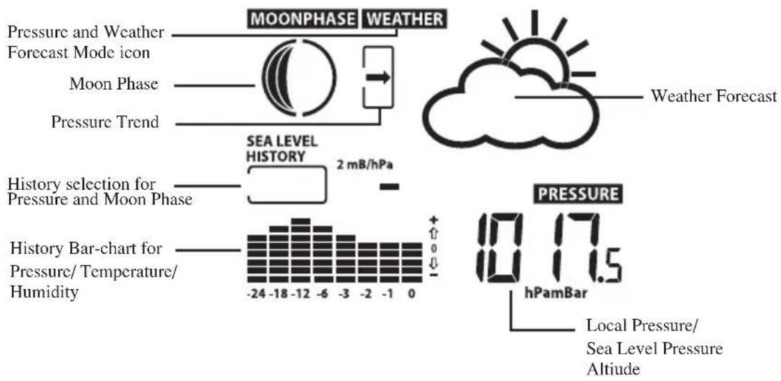
WEATHER re and Weather Forecast Mode
- Current pressure, trend, and history bar-chart
- Weather forecast
- Moon phase
TIME Clock and Alarm Mode
- Radio Controlled clock showing current time and calendar
- Single alarm, weekday alarm and pre-alarm


Sunrise/Sunset Mode
- Sunrise and sunset times
- Longitude and Latitude of local area

IN OUT Temperature and Humidity Mode
- Temperature and humidity trend and readings for indoor and selected channel
- Comfort level
- Dew point
- Temperature alerts

RAIN Rain Mode
- Precipitation amount for last hour, last 24 hour, yesterday, last week and last month
- Rainfall alert

flowchart
graph TD
    A["Rain Statistic"] --> B["RAIN"]
    C["Sensor Battery Status"] --> B
    D["Rain Icon"] --> B
    E["10.2 mm/hr"] --> F["ALARM HI"]
    G["Rain Alert"] --> F
    H["Rain Rate Display"] --> F
    I["Rainfall"] --> F
WIND Wind Mode
- Wind Chill
- Temperature at place of anemometer
- Wind direction
- Wind speed
- Wind gust
- Alert for wind speed and wind gust speed

Customizing your Weather Station
To fully customize the weather station to your local settings and personal preferences, the following settings are required. Please refer to the appropriate sections for detailed instructions.
Required:
-Setting Pressure Parameters during Initial Start-Up (Pressure and Weather Forecast Mode)
-Setting up the Time, Date and Language (Clock and Alarm Mode)
-Setting up the Location Data (Sunrise/Sunset Mode)
Optional:
-Setting up the Time Alarms (Clock and Alarm Mode)
-Setting up the Temperature Alerts (Temperature and Humidity Mode)
-Setting up the Daily Rainfall Alerts (Rain Mode)
-Setting up the Wind Alerts (Winds Mode)
Navigating between Different Modes
There are 6 modes available on the main console unit, and each one displays a different category of data. When display is in a certain mode, its corresponding icon will start flashing.
To navigate between the different modes from the main console unit, press UP to cycle through the modes in a clockwise direction or DOWN to cycle through the modes in an anti-clockwise direction.
Using the Different Weather Modes
1. Pressure and Weather Forecast Mode
This part of the display indicates the current pressure, sea level pressure, weather forecast, moon phase and pressure trend.
A number of historical statistics can also be viewed, such as the sea-level pressure values for the last 24 hours, moon phase for the previous and next 39 days, as well as a pressure/ temperature/humidity history bar-chart.
Pressure values may be displayed in Hg, hPa/mBar or mmHg, and altitude values may be displayed in meters or feet.
Accessing Pressure and Weather Forecast Mode
From the main console unit: Press UP or DOWN until the weather forecast icon WEATHER on the upper left of the display starts flashing.
Setting Pressure Parameters during Initial Start-Up
During the initial start-up of the main console unit, all functions in Pressure and Weather Forecast mode will be locked until the pressure settings are configured.
- Choose Pressure Units:
The unit icon “inHg” or “mmHg” or “hPa/mBar” should be flashing. Press UP or DOWN to select pressure unit as inHg, hPa/mBar or mmHg
Press SET to confirm your selection.
- Choose Altitude Units:
Press UP or DOWN to select altitude unit as feet or meters.
Press SET to confirm your selection.
- Set Altitude:
Press UP or DOWN to adjust value. Press and hold either button for fast advance.
Press SET to confirm your selection.
- Upon completion the display will be returned to Pressure and Weather Forecast Mode.
Note: By no input the unit starts flashing and the instrument chooses automatically hPa/mBar
Viewing Pressure and Altitude Data
In Pressure and Weather Forecast Mode, each press of SET rotates display between:
- Sea level pressure
- Local pressure
- Local altitude
Setting the Sea Level Pressure
- In Pressure and Weather Forecast Mode, press SET until the sea level pressure is displayed.
- Press and hold SET. The Sea Level Pressure display should be flashing.
- Set Sea Level Pressure:
Press UP or DOWN to adjust value. Press and hold either button for fast advance.
Press SET to confirm your selection.
- Upon completion the display will be returned to Pressure and Weather Forecast Mode.
Setting the Pressure and Altitude Units
- In Pressure and Weather Forecast Mode, press SET until local pressure is displayed.
- Press and hold MEMORY. The pressure unit should be flashing.
- Set Local Pressure Units:
Press UP or DOWN to adjust unit.
Press MEMORY to confirm your selection.
- Set Altitude Units:
Press UP or DOWN to adjust value.
Press MEMORY to confirm your selection.
- Set Sea-Level Pressure Units:
Press UP or DOWN to adjust value.
Press MEMORY to confirm your selection.
- Upon completion the display will be returned to Pressure and Weather Forecast Mode.
Viewing the Sea Level Pressure History
- In all modes, pressing HISTORY will toggle the sea level pressure display.
- When sea level pressure is displayed, press HISTORY repeatedly to view sea level pressure data for each of the last 24 hours.
- If no buttons are pressed for 5s, the display automatically returns to Pressure and Weather Forecast Mode.
Viewing the Pressure/ Temperature/ Humidity Bar-Charts
The bar-chart on the display can be configured to display the history data for sea-level pressure, temperature or humidity for channel 1.
In Pressure and Weather Forecast Mode, press and hold ALARM/CHART to toggle the bar-chart between:
- Sea-level pressure (“PRESSURE” should be displayed)
- Temperature (Thermometer icon and "CH1" should be displayed)
- Humidity (RH icon and “CH1” should be displayed)
Viewing Moon Phase History and Forecast
- In Pressure and Weather Forecast Mode, press MEMORY.
- “+ 0 days” should be flashing.
- View Moon Phase History / Forecast:
Press UP or DOWN to choose number of days forward (+ days) or backward (- days) from current date. Press and hold either button for fast advance.
The corresponding moon phase will be shown.
- To exit, press MEMORY.
Otherwise, if no buttons are pressed for 5s the display automatically returns to Pressure and Weather Forecast Mode.
Understanding the Moon Phase Diagram

natural_image
Sequence of black-and-white circular patterns resembling celestial bodies or moon cycles (no text or symbols)Full moon
New moon
Understanding the Weather Forecast Display
| Display Weather Forecast Status | |
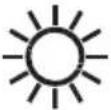 | Sunny |
 | Partly Cloudy |
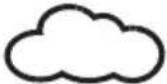 | Cloudy |
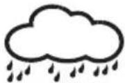 | Rain |
 | Unstable Weather |
 | Snow |
NOTE:
- The accuracy of a general pressure-based weather forecast is about 70%.
- The weather forecasts. It may not necessarily reflect the current situation.
- The "Sunny" icon, as applies to night time, implies clear weather.
2. Clock and Alarm Mode
The main console unit can be configured to display the time, calendar or UTC time. There are three time alarms available on the console unit:
Single alarm: activated once at specified time
Weekday alarm: activated everyday from Monday to Friday at specified time
Pre-alarm: activated at specified time interval (30 min) ahead of weekday alarm, if channel 1 temperature falling to +2 °C or below.
The snooze duration for the above alarms can also be programmed (0-15 min).
Accessing Clock and Alarm Mode
From the main console unit: Press UP or DOWN until the clock icon TIME beside the time/date display starts flashing.
Setting up the Time, Date and Language
- In Clock and Alarm Mode, press and hold SET to enter clock and calendar setup.
- The day of week should start flashing in the display.
Set Language:
Press UP or DOWN to select language for day of week: English, German, French, Italian, Spanish or Dutch
Press SET to confirm your selection.
- Select City Code:
Press UP or DOWN to select city code for your local area. Refer to P.63 for a list of available codes.
Press SET to confirm your selection.
- (if USR was chosen for city code) Set Minute for Latitude:
You will be asked to enter your latitude in minutes.
Press UP or DOWN to adjust value. Press and hold either button for fast advance.
Press SET to confirm your selection. Repeat above procedure to set seconds for latitude, minutes for longitude and seconds for longitude.
- (if USR was chosen for city code) Set Time Zone:
Press UP or DOWN to adjust value in resolution of 30 min. Press and hold either button for fast advance. Press SET to confirm your selection.
- (if USR was chosen for city code or city is in a DST zone)
Set Daylight Saving Time Option:
Press UP or DOWN to turn DST option on or off. Press and hold either button for fast advance. Press SET to confirm your selection.
-
Repeat the above instructions to set year, month, day, calendar display format (day/month or month/day), time display format (12 hr/ 24 hr), local hour and local minutes.
-
Upon completion the display will return to normal Clock and Alarm Mode.
Note: Press and hold SET anytime during the setup to return to normal Clock and Alarm Mode. All settings made will be discarded.
Rotating between Different Clock/Calendar Displays
In Clock and Alarm Mode, each press of SET rotates clock display between:
-Hour: Minute: Weekday
-Hour: Minute for UTC (Coordinated Universal Time)
-Hour: Minute: City
-Hour: Minute: Second
-Month: Day: Year (or Day: Month Year depending on settings)
Activating/Deactivating the Time Alarms
- In Clock and Alarm Mode, each press of ALARM/CHART rotates clock display between:
-Weekday Alarm Time (displays OFF if weekday alarm deactivated)
- Single Alarm Time (displays OFF if single alarm deactivated)
- Pre-Alarm Time (displays OFF if pre-alarm deactivated)
- When the above alarms are displayed, pressing UP or DOWN will activate/deactivate the corresponding alarm.
Note: Press SET anytime during alarm selection mode to return to normal clock display.
Setting up the Time Alarms
-
In Clock and Alarm Mode, press ALARM/CHART to select alarm which you wish to configure.
-
Press and hold ALARM/CHART until hour starts flashing in the display
-
Set Alarm Hour:
Press UP or DOWN to adjust value. Press and hold either button for fast advance.
Press ALARM/CHART to confirm your selection.
- Set Alarm Minutes:
Press UP or DOWN to adjust value. Press and hold either button for fast advance.
Press ALARM/CHART to confirm your selection.
- Set Duration of Snooze Function (all three alarms share same snooze time duration):
Press UP or DOWN to adjust value. Press and hold either button for fast advance.
Press ALARM/CHART to confirm your selection.
- Upon completion the display will be returned to the alarm selection screen.
Note: Pre-alarm cannot be activated if weekday alarm or single alarm is not enabled.
Disabling/Entering Snooze when Time Alarms are Activated
To Enter Snooze:
Press SNOOZE to enable snooze function.
Note: Alarm will automatically enter snooze mode if no key is pressed after the alarm sounds for 2 minutes. This will occur for a maximum of three times.
To Disable Alarm(s):
Press ALARM/CHART to disable the alarm (s).
Note: For weekday alarm, pressing ALARM/CHART will only disable the alarm for the current day. The alarm will be activated again the next day (if it falls within Monday to Friday).
Activating/Deactivating Radio Clock Reception
The main console unit synchronizes the time and date with radio clock broadcasts to maintain atomic clock precision.
To turn this function on/off:
Press and hold UP.
If RC reception is activated, a triangular tower icon will start flashing beside the clock icon.
If RC reception is deactivated, the triangular tower icon will disappear.
Icon RC Reception Strength

(Blinks)
Undefined data

Reception failed for 24 hours

Weak signal, but can be decoded

Strong signal
Note: The radio controlled signal for time (DCF 77) is transmitted from the central atomic clock in Frankfurt/Main in short intervals. It has a reception range of approx. 1500 km. Obstructions such as concrete walls can reduce the signal range.
3. Sunrise/Sunset Mode
The main console unit computes the sunrise and sunset times from the user-configured location data.
This includes the longitude, latitude, time zone and DST (Daylight Saving Time). Choosing a suitable city code for your area will automatically generate the correct values for the location data.
Should you wish to input your own location data or if a suitable city code could not be found, choose “USR” as the city code during setup.
A searching function is also available, which allows the sunrise/sunset times for different dates to be viewed.
Accessing Sunrise/Sunset Mode
From the main console unit: Press UP or DOWN until the sunrise and sunset icons the lower left of the display start flashing.


on
Setting up the Location Data
- In Sunrise/Sunset Mode, press and hold SET to enter location data setup.
- The city code in the Time and Alarm display should start flashing.
Set City Info:
Press UP or DOWN to select city code for your local area. A list of all available cities is enclosed. The corresponding longitude and latitude will be shown along with the city. Should you wish to input your own geographical coordinates, choose “USR” as the city code Press SET to confirm your selection.
- If "USR" was chosen, you will be asked to input your geographical coordinates.
Set Degree of Latitude:
Press UP or DOWN to adjust value. Press and hold either button for fast advance.
Press SET to confirm your selection.
- Repeat above procedure to set minute of latitude, degree of longitude, minute of longitude, time zone of the city, and DST selection.
- Upon completion the display will be returned to Sunrise/Sunset Mode.
Note: Press and hold SET anytime during the setup to return to normal Clock and Alarm Mode. All settings made will be discarded.
Viewing the Location Data
In Sunrise/Sunset Mode, each press of SET rotates display between:
-Time and sunrise/ sunset Times
-Calendar and sunrise/ sunset Times
-Calendar and longitude/ latitude
Viewing Sunrise/Sunset Times for Different Dates
- In Sunrise/Sunset Mode, press MEMORY.
- The date should be flashing.
Press UP or DOWN to adjust date. Press and hold either button for fast advance.
The corresponding sunrise and sunset times will be displayed for the selected date.
- Press MEMORY or SET to return display to Sunrise/Sunset Mode.
Understanding the Sunrise/Sunset Display
The sunrise time being displayed differs during the morning and the afternoon/night.
From 12 am to 12 pm: The sunrise time for the current day will be displayed.
From 12 pm to 12 am: The sunrise time for the next day will be displayed. “NEXT DAY” icon will be displayed above the sunrise time.
At certain locations (especially those at high latitudes), sunrise and sunset events may not occur within a 24 hour time frame.
Display Sunrise status Display Sunset status
FULL Sunrise at previous day FULL Sunset at next day or later
---- No sunrise for the whole day ---- No sunset for the whole day
4. Temperature and Humidity Mode
The weather station supports up to 5 remote thermo-hygro sensors, each sensor corresponding to a separate channel for the temperature and relative humidity display. The temperature may be shown in degrees Celsius °C or degrees Fahrenheit °F. The trend (rising, steady or falling) of all values is also indicated on the display.
The main console unit uses the indoor temperature and humidity data to compute a comfort level rating of Wet, Comfort or Dry.
A temperature alert function is available for each channel. It can be programmed to sound if the channel temperature exceeds or falls below the pre-configured upper and lower limits.
Note: The temperature alerts have a 0.5 ^ hysteresis to prevent the alerts from sounding constantly due to small fluctuations near the alert value. This means that after the temperature reaches the alert value, it will have to fall below the alert value plus the hysteresis to deactivate the alert.
Accessing Temperature and Humidity Mode
From the main console unit: Press UP or DOWN until the IN icon and the OUT icon on the upper right of the display starts flashing.
Viewing Temperature and Humidity Display for each Channel
For Static Display:
In Temperature and Humidity Mode, each press of CHANNEL rotates display between different channels.
For Cycling Display:
To enable automatic rotating between different channel displays, press and hold CHANNEL, until the G icon is displayed. Each valid channel will now be alternately displayed for 5s.
Press and hold CHANNEL to deactivate ist.
Rotating Between Temperature and Dew Point Display
In Temperature and Humidity Mode, each press of SET rotates temperature display between:
- Temperature and Relative Humidity
- Dew Point Temperature and Relative Humidity
Setting Units for Temperature Display (°C or °F)
In Temperature and Humidity Mode, press and hold SET to convert units between degrees Celsius ^ C and degrees Fahrenheit ^ F.
Activating/Deactivating the Temperature Alerts
-
In Temperature and Humidity Mode, each press of ALARM/CHART rotates channel temperature display between:
-
Current Temperature for corresponding channel
- Upper Temperature Alert (displays OFF if deactivated):▲ icon displayed
-
Lower Temperature Alert (displays OFF if deactivated): ▼icon displayed
-
When the above alerts are displayed, pressing UP or DOWN will activate/deactivate the corresponding alert.
Setting up the Temperature Alerts
- In Temperature and Humidity Mode, press ALARM/CHART to select alarm which you wish to configure.
- Press and hold ALARM/CHART until channel temperature and ▲ or ▼ icon starts flashing in the display.
- Set Value for Temperature Alert:
Press UP or DOWN to adjust value. Press and hold either button for fast advance.
Press ALARM/CHART to confirm your selection. - Upon completion the display will be returned to the temperature alert selection screen.
Disabling when Temperature Alarms are Activated
To Disable Temperature Alarm(s):
Press ALARM/CHART to disable the alarm (s).
Viewing the Max/Min Channel Temperature and Humidity
In Temperature and Humidity Mode, each press of MEMORY rotates channel temperature and humidity display between:
- Current temperature and humidity at remote sensor
- Minimum temperature and humidity at remote sensor
- Maximum temperature and humidity at remote sensor
Resetting the Max/Min Channel Temperature and Humidity Memory
In Temperature and Humidity Mode, press and hold MEMORY to clear memory for all channels.
Remote Sensor Status
The wave icon above the current channel display shows the connection status of the corresponding remote sensor:
Icon Status


Searching for remote sensor signals
Corresponding remote sensor successfully linked
No signals received for more than 15 minutes
Activating Main Console Unit to Search for All Remote Sensor Signals
The main console unit may be manually activated to search for signals from all remote sensors. Press and hold DOWN to enforce a search.
5. Rain Mode
The main console unit records the total amount of rainfall for the last hour, last 24 hours, yesterday, last week and last month. The rainfall may be displayed in mm or inches.
A daily rainfall alert function is available which can be programmed to sound if the daily rainfall exceeds a pre-configured limit.
Accessing Rain Mode
From the main console unit: Press UP or DOWN until the RAIN icon RAIN on the display starts flashing.
Viewing Rain Statistics
In Rain Mode, each press of SET or MEMORY rotates display between different rain statistics:
- Last hour
- Last 24 hour
- Yesterday
- Last week
- Last month
Tip: For an estimation of the rain rate, the Last Hour rainfall value can be understood as “inch/hr” or “mm/hr”.
Resetting the Rainfall Statistics Memory
In Rain Mode, press and hold MEMORY to reset all rainfall statistics.
Setting Units for Rain Display (inch or mm)
In Rain Mode, press and hold SET to convert units between mm and inches.
Activating/Deactivating the Daily Rainfall Alert
- In Rain Mode, each press of ALARM/CHART rotates display between the current rainfall statistics and the daily rainfall alert (“ALARM HI” will be displayed).
If the alert is deactivated, "OFF" will be shown, otherwise the rainfall alert value is shown.
- When the rainfall alert is displayed, pressing UP or DOWN will activate/deactivate it.
Setting up the Daily Rainfall Alert
- In Rain Mode, press ALARM/CHART to display rainfall alert.
- Press and hold ALARM/CHART until rainfall alert and “ALARM HI” starts flashing in the display.
- Set Value for Rainfall Alert:
Press UP or DOWN to adjust value. Press and hold either button for fast advance.
Press ALARM/CHART to confirm your selection. - Upon completion the display will be returned to the rainfall alert display.
Disabling when Daily Rainfall Alert is Activated
To Disable Rainfall Alert:
Press ALARM/CHART to disable the alert.
6. Wind Mode
The wind direction is shown by an animated compass display. Its angle can be displayed as compass points (i.e. NW) or in bearings from the north (i.e. 22.5°).
The upper left of the wind display can be set to indicate the temperature at the anemometer or the temperature adjusted with a wind chill factor.
The lower left of the wind display indicates the average wind speed for the last 10 minutes, as well as gust, wind speed alert and gust alert information. It can also show records of the maximum values of wind speed and gust attained for the current day.
The wind speed and gust alert functions can be programmed to sound if the wind speed or gust exceeds a pre-configured limit. The wind speed may be displayed in km/h, mph, m/s or knots.
Note: The wind speed alert has a 5 mph hysteresis and the wind gust speed alert has a 7 mph hysteresis. The hysteresis is to prevent the alerts from sounding constantly due to small fluctuations near the alert value. This means that after the wind speed reaches the alert value, it will have to fall below the alert value plus the hysteresis to deactivate the alert.
Accessing Wind Mode
From the main console unit: Press UP or DOWN until the WIND icon WIND on the display starts flashing.
Configuring Wind Display
In Wind Mode, each press of SET rotates display between:
- Temperature with wind chill, wind direction in bearings
- Temperature with wind chill, wind direction in compass points
- Temperature at anemometer, wind direction in compass points
- Temperature at anemometer, wind direction in bearings
Setting Units for Wind Speed Display (km/h, mph, m/s or knots)
In Wind Mode, press and hold SET to convert wind speed units between km/h, mph, m/s or knots.
Viewing Wind Statistics
In Wind Mode, each press of MEMORY rotates wind speed display between:
- Current wind speed
- Daily maximum wind speed (“DAILY MAX” is displayed)
- Gust speed ("GUST" is displayed)
- Daily maximum gust speed ("GUST DAILY MAX" is displayed)
Resetting the Wind Statistics Memory
In Wind Mode, press and hold MEMORY to reset all wind statistics.
Activating/Deactivating Wind Alerts
-
In Wind Mode, each press of ALARM/CHART rotates wind speed display between:
-
Current wind speed
- Wind speed alert ("ALARM HI" displayed)
- Gust alert ("GUST ALARM HI" displayed)
If the alert is deactivated, "OFF" will be shown, otherwise the alert value is shown.
- When a wind alert is displayed, pressing UP or DOWN will activate/deactivate it.
Setting up the Wind Alerts
- In Wind Mode, press ALARM/CHART to select alarm which you wish to configure.
- Press and hold ALARM/CHART until alert and corresponding icon starts flashing in the display.
- Set Value for Alert:
Press UP or DOWN to adjust value. Press and hold either button for fast advance.
Press ALARM/CHART to confirm your selection. - Upon completion the display will be returned to the wind alert selection screen.
Disabling when Wind Alert is Activated
To Disable Wind Alert:
Press ALARM/CHART to disable the alert.
PC-Connection
- Delivered with setup CD-ROM (in English and German) and 2 metres of cable for the base-computer link.
- Please read the manual on the CD-ROM carefully.
- Possible storage of 200 sets of data, a set of data is a recording of information at that point in time from all sensors.
- Minimum system requirement: Windows 98 or above.
- Read the software's manual carefully, which you will find on the CD.
Maintenance
Changing Batteries
The battery statuses of the sensors are checked every hour. If the low battery indicators light up, replace the batteries for the corresponding unit immediately.
Changing Batteries for the Main Console Unit
- Remove the latch at the back and replace all batteries. Do not mix old and new batteries.
- Replace the cover.
Changing Batteries for the Remote Sensors
- Replace the batteries following the setup instructions for the corresponding sensor.
- When the batteries are properly installed, the sensor will resume sending signals to the main console unit.
To enforce a search immediately for all remote signals, press and hold DOWN on the main console unit.
Cleaning
The main console unit and outer casings for the remote sensors can be cleaned with a damp cloth.
Small parts can be cleaned with a cotton tip or pipe-cleaner.
Never use any abrasive cleaning agents and solvents. Do not immerse any units with electronic parts in water or under running water.
Anemometer
- Check that the wind vane and wind cups can spin freely and are free from dirt, debris or spider webs.
Rain Sensor
Like all rain gauges, the rain sensor is prone to blockages due to its funnel shape. Checking and cleaning the rain sensor from time to time will maintain the accuracy of rain measurements.
- Detach the protective screen and lid. Remove any dirt, leaves or debris by cleaning the items with soapy water and a damp cloth. Clean small holes and parts with a cotton tips or pipe-cleaner.
- Look out for spiders or insects that might have crawled into the funnel.
- Also clean the swinging mechanism with a damp cloth.
Troubleshooting
The display shows dashes “---” for weather parameter(s)
The display will show “---” when the wireless link is lost with the remote sensor for the following periods:
Thermo-hygro Sensor - 15 minutes
Anemometer (Wind Sensor) - 15 minutes
Rain Sensor - 30 minutes
Check or replace the batteries for the corresponding sensor. Then press and hold DOWN to enforce a search for all remote signals.
If the above does not solve the problem, check the wireless transmission path from the corresponding sensor to the main console unit and change their locations if necessary.
Although wireless signals can pass through solid objects and walls, the sensor should ideally be within the line of sight of the console unit.
The following may be the cause of reception problems:
- Distance between remote sensor and main console unit too long. (Maximum transmission distance in open area conditions is 100m)
- Signal shielding materials such as metal surfaces, concrete walls or dense vegetation in the path of transmission.
- Interferences from wireless devices (such as cordless phones, radio headsets, baby listening devices) and electronic appliances.
The weather readings do not correlate with measurements from TV, radio or official weather reports.
Weather data can vary considerably due to different environmental conditions and placement of weather sensors.
Check the placement tips included in this manual to site your sensors in the best possible way.
The weather forecast is inaccurate.
The weather forecast is a prediction of weather after 12-24 hours, and may not reflect current weather conditions.
PRECAUTIONS
This product is engineered to give you years of satisfactory service if you handle it carefully. Here are a few precautions:
- Do not immerse the unit in water.
- Do not clean the unit with abrasive or corrosive materials. They may scratch the plastic parts and corrode the electronic circuit.
- Do not subject the unit to excessive force, shock, dust, temperature or humidity, which may result in malfunction, shorter electronic life span, damaged battery and distorted parts.
- Do not tamper with the unit's internal components. Doing so will invalidate the warranty on the unit and may cause unnecessary damage. The unit contains no user-serviceable parts.
- Only use fresh batteries as specified in the user's manual. Do not mix new and old batteries as the old ones may leak.
- Use alkaline batteries only. Observe correct polarity. Low batteries should be changed soon to avoid the damage resulting from a leaking battery. Batteries contain harmful acids. Wear protective glasses and gloves when handling with leaked batteries.
Attention: Please do not dispose of old electronic devices and used batteries in household waste.
To protect the environment, take them to your retail store or to appropriate collection sites according to national or local regulations.
- Always read the user's manual thoroughly before operating the unit.
CAUTION
- The content of this manual is subject to change without further notice.
- Due to printing limitation, the displays shown in this manual may differ from the actual display.
- The contents of this manual may not be reproduced without the permission of the manufacturer.
Remark: The front side of the casing shows, under certain angles, 2 flow lines. These flow lines are caused by the production process of the casing and, unfortunately, are unavoidable. They have, however, no effect whatsoever on the operation of the device.
EC-DECLARATION OF CONFORMITY
Product : SINUS
This product contains the approved transmitter and complies with the essential requirements of Article 3 of the R&TTE 1999/5/EC Directives, if used for its intended use and that the following standard(s) has/have been applied:
Efficient use of radio frequency spectrum
(Article 3.2 of the R&TTE Directive)
applied standard(s)
EN 300 220-3:2000
Electromagnetic compatibility
(Article 3.1.b of the R&TTE Directive)
applied standard(s)
EN 301 489-1,3:2000
Low voltage directive
applied standard(s)
EN 60950-1:2001
Additional information:
The product is therefore conform with
the EMC Directive 89/336/EC and R&TTE Directive 1999/5/EC
(appendix II) and carries the respective CE marking.
RTTE Compliant Countries :
All EU countries, Switzerland CH
Power
Main unit : use 4 pcs UM-3 or "AA" 1.5V battery
Remote Thermo.-Hygro unit : use 2 pcs UM-3 or “AA” 1.5V battery
Remote Anemometer unit : use 2 pcs UM-3 or "AA" 1.5V battery
Remote Rain gauge unit : use 2 pcs UM-3 or “AA” 1.5V battery
Weight
Main unit : 231g (without battery)
Remote Thermo.-Hygro unit : 65g (without battery)
Remote Anemometer unit : 315g (without battery)
Remote Rain gauge unit : 290g (without battery)
Dimension
Main unit : 185.8(L) x 136.9(H) x 32(D) mm
Remote Thermo.-Hygro unit : 55.5(L) x 101(H) x 24(D) mm
Remote Anemometer unit : 405(L) x 375(H) x 160(D) mm
Remote Rain gauge unit : 163(L) x 177(H) x 119(D) mm
Appendix
City Codes
US and Canadian Cities
City Code Zone DST City Code Zone DST
| Offset Offset | |||||||
| Atlanta, Ga. | ATL | -5 | SU | Montreal, Que., Can. | YMX | -5 | SU |
| Austin, Tex. | AUS | -6 | SU | Nashville, Tenn. | BNA | -6 | SU |
| Baltimore, Md. | BWI | -5 | SU | New Orleans, La. | MSY | -6 | SU |
| Birmingham, Ala. | BHM | -6 | SU | New York, N.Y. | NYC | -5 | SU |
| Boston, Mass. | BOS | -5 | SU | Oklahoma City, Okla. | OKC | -6 | SU |
| Calgary, Alba., Can. | YYC | -7 | SU | Omaha, Neb. | OMA | -6 | SU |
| Chicago, IL | CGX | -6 | SU | Ottawa, Ont., Can. | YOW | -5 | SU |
| Cincinnati, Ohio | CVG | -5 | SU | Philadelphia, Pa. | PHL | -5 | SU |
| Cleveland, Ohio | CLE | -5 | SU | Phoenix, Ariz. | PHX | -7 | NO |
| Columbus, Ohio | CMH | -5 | SU | Pittsburgh, Pa. | PIT | -5 | SU |
| Dallas, Tex. | DAL | -6 | SU | Portland, Ore. | PDX | -8 | SU |
| Denver, Colo. | DEN | -7 | SU | San Antonio, Tex. | SAT | -6 | SU |
| Detroit, Mich. | DTW | -5 | SU | San Diego, Calif. | SAN | -8 | SU |
| El Paso, Tex. | ELP | -7 | SU | San Francisco, Calif. | SFO | -8 | SU |
| Houston, Tex. | HOU | -6 | SU | San Jose, Calif. | SJC | -8 | SU |
| Indianapolis, Ind. | IND | -5 | NO | Seattle, Wash. | SEA | -8 | SU |
| Jacksonville, Fla. | JAX | -5 | SU | St. Louis, Mo. | STL | -6 | SU |
| Las Vegas, Nev. | LAS | -8 | SU | Tampa, Fla. | TPA | -5 | SU |
| Los Angeles, Calif. | LAX | -8 | SU | Toronto, Ont., Can. | YTZ | -5 | SU |
| Memphis, Tenn. | MEM | -6 | SU | Vancouver, B.C., Can. | YVR | -8 | SU |
| Miami, Fla. | MIA | -5 | SU | Vancouver, Canada | VAC | -8 | SU |
| Milwaukee, Wis. | MKE | -6 | SU | Washington, D.C. | DCA | -5 | SU |
| Minneapolis, Minn. | MSP -6 | SU | |||||
World Cities
City Code Zone DST City Code Zone DST
Offset Offset
Addis Ababa, Ethiopia ADD 3 NO Cairo, Egypt CAI 2 sg
| Adelaide, Australia | ADL | 9.5 | SA | Calcutta, India(as Kolkata) | CCU | 5.5 | NO |
| Algiers, Algeria | ALG | 1 | NO | Cape Town, South Africa | CPT | 2 | NO |
| Amsterdam, Netherlands | AMS | 1 | SE | Caracas, Venezuela | CCS | -4 | NO |
| Ankara, Turkey | AKR | 2 | SE | Chihuahua, Mexico | CUU | -6 | SU |
| Asuncion, Paraguay | ASU | -3 | sp | Copenhagen, Denmark | CPH | 1 | SE |
| Athens, Greece | ATH | 2 | SE | Cordoba, Argentina | COR | -3 | NO |
| Bangkok, Thailand | BKK | 7 | NO | Dakar, Senegal | DKR | 0 | NO |
| Barcelona, Spain | BCN | 1 | SE | Dublin, Ireland | DUB | 0 | SE |
| Beijing, China | BEJ | 8 | NO | Durban, South Africa | DUR | 2 | NO |
| Belgrade, Yugoslavia | BEG | 1 | SE | Frankfurt, Germany | FRA | 1 | SE |
| Berlin, Germany | BER | 1 | SE | Glasgow, Scotland | GLA | 0 | SE |
| Birmingham, England | BHX | 0 | SE | Guatemala City, Guatemala | GUA | -6 | NO |
| Bogota, Colombia | BOG | -5 | NO | Hamburg, Germany | HAM | 1 | SE |
| Bordeaux, France | BOD | 1 | SE | Havana, Cuba | HAV | -5 | SH |
| Bremen, Germany | BRE | 1 | SE | Helsinki, Finland | HEL | 2 | SE |
| Brisbane, Australia | BNE | 10 | NO | Hong Kong, China | HKG | 8 | NO |
| Brussels, Belgium | BRU | 1 | SE | Irkutsk, Russia | IKT | 8 | SK |
| Bucharest, Romania | BBU | 2 | SE | Jakarta, Indonesia | JKT | 7 | NO |
| Budapest, Hungary | BUD | 1 | SE | Johannesburg, South Africa | JNB | 2 | NO |
| Buenos Aires, Argentina | BUA | -3 | NO | Kingston, Jamaica | KIN | -5 | NO |
City Code Time DST City Code Time DST
Zone Zone
Kinshasa, Congo FIH 1 NO Oslo, Norway OSL 1 SE
| Kuala Lumpur, Malaysia KUL 8 NO Panama City, Panama PTY -5 NO | |||||||
| La Paz, Bolivia | LPB | -4 | NO | Paris, France | PAR | 1 | SE |
| Lima, Peru | LIM | -5 | NO | Perth, Australia | PER | 8 | NO |
| Lisbon, Portugal | LIS | 0 | SE | Prague, Czech Republic | PRG | 1 | SE |
| Liverpool, England | LPL | 0 | SE | Rangoon, Myanmar | RGN | 6.5 | NO |
| London, England | LON | 0 | SE | Reykjavyk, Iceland | RKV | 0 | NO |
| Lyon, France | LYO | 1 | SE | Rio de Janeiro, Brazil | RIO | -3 | sb |
| Madrid, Spain | MAD | 1 | SE | Rome, Italy | ROM | 1 | SE |
| Manila, Philippines | MNL | 8 | NO | Salvador, Brazil | SSA | -3 | NO |
| Marseille, France | MRS | 1 | SE | Santiago, Chile | SCL | -4 | sc |
| Melbourne, Australia | MEL | 10 | SA | Sao Paulo, Brazil | SPL | -3 | sb |
| Mexico City, Mexico | MEX | -6 | SU | Shanghai, China | SHA | 8 | NO |
| Milan, Italy | MIL 1 SE | Singapore, Singapore SIN 8 NO | |||||
| Montevideo, Uruguay | MVD | -3 | SM | Sofia, Bulgaria | SOF | 2 | SE |
| Moscow, Russia | MOW | 3 | SK | Stockholm Arlanda, Sweden | ARN | 1 | SE |
| Munich, Germany | MUC | 1 | SE | Sydney, Australia | SYD | 10 | SA |
| Nairobi, Kenya | NBO | 3 | NO | Tokyo, Japan | TKO | 9 | NO |
| Nanjing (Nanking), China | NKG 8 NO Tripoli, Libya | TRP 2 NO | |||||
| Naples, Italy | NAP | 1 | SE | Vienna, Austria | VIE | 1 | SE |
| New Delhi, India | DEL | 5.5 | NO | Warsaw, Poland | WAW | 1 | SE |
| Odessa, Ukraine | ODS | 2 | SE | Zurich, Switzerland | ZRH | 1 | SE |
| Osaka, Japan | KIX 9 NO | ||||||
DST definition
SA = Australian DST.
SB = South Brazilian DST. Changes annually.
SC = Chile DST
SE = Standard European DST.
SG = Egypt DST
SH = Havana, Cuba DST
SI = Iraq and Syria DST
SK = Irkutsk & Moscow DST
SM = Montevideo, Uruguay DST
SN = Namibia DST
SP = Paraguay DST
SQ = Iran DST maybe changed annually.
ST = Tasmania DST
SU = Standard American DST.
SZ = New Zealand DST
NO DST = no = Places that do not observe DST
ON = Always add 1 hour with local standard time
Technical Specifications
Weather Station Receivers
Receiver (Supply=6.0V, Ta=23°C) and Sensor unit (Supply=3.0V, Ta=23°C)
RF Transmission Frequency 434 MHz
RF Reception Range 100 meters Maximum (Line of Sight)
Barometric Pressure Range 500 hpa to 1100hpa (14.75 inHg to 32.44 inHg),
(At sea level) (374.5 mmHg to 823.8 mmHg)
Altitude Compensation Range -200m to +5000 m (-657 ft to 16404 ft)
Barometric Pressure resolution 0.1 hpa (0.003 inHg, 0.08 mmHg)
Barometric Pressure accuracy +/- 5 hpa (0.015 inHg, 0.38 mmHg)
Outdoor Temperature Display Range -40°C to 80°C (-40°F to 176°F)
Indoor Temperature Display Range -9.9°C to 60°C (14.2°F to 140°F)
Operating Temperature 0^ C to 50^ C ( 32^ F to 122^ F)
Storage Temperature -20°C to 60°C (-4°F to 140°F)
Temperature accuracy +/- 1°C or +/- 2°F
Temperature resolution 0.1°C or 0.2°F
Humidity Display Range 0% to 99%
Humidity accuracy +/-5%
Humidity resolution 1%
Receiving Cycle
Remote Thermo./Hygro. around 47s
Rain gauge 183s
Wind sensor 33s
Sunrise and Sunset Accuracy +/- 3min (latitude within +/- 50°)
Wind Direction Range 16 positions
Wind Direction Accuracy +/-11.25°
Wind Direction Resolution 22.5°
Wind Direction Starting Threshold 3mph
Wind Speed Range 0 to 199.9mph (199.9 Km/h, 173.7 Knots, 89.3 m/s)
Wind Speed Accuracy +/- (2mph + 5%)
Wind Speed Starting Threshold 3mph
Wind/Gust Speed Disply Update Interval 33 seconds
Wind/Gust Sampling Interval 11 seconds
1h/24h/yesterday Rainfall Range 0.0 to 1999.9 mm (78.73 inch)
Last week/ last month Rainfall Range 0 to 19999 mm (787.3 inch)
Temperature Sensing Cycle (indoor) 10s
Humidity Sensing Cycle (indoor) 10s
CD ROM (English and German)
Cable for the base-computer (2metres)
System requirement: Windows'98 or above


- Professional Weather Center
- Introduction
- Main Console Unit
- Remote Weather Sensors
- Contents of Complete Weather Station Kit
- Installing your weather station
- Setting up the Remote Weather Sensors
- Setting up the Thermo-Hygro Sensor(s)
- Placement tips:
- Setting up the Rain Sensor
- Setting up the Anemometer (wind sensor)
- Setting up the Main Console Unit
- Starting up the Main Console Unit
- Using your Weather Station
- Display
- Section I
- Weather Forecast
- Pressure
- Moon phase
- Section II
- Radio Controlled Clock
- Alarms
- Section III
- Sunrise time and sunset time
- Section IV
- Temperature and relative humidity, with trend indication
- Comfort level indicator
- Section V
- Rainfall measurement
- Section VI
- Wind
- Description of Graphics
- WEATHER re and Weather Forecast Mode
- TIME Clock and Alarm Mode
- Sunrise/Sunset Mode
- IN OUT Temperature and Humidity Mode
- RAIN Rain Mode
- WIND Wind Mode
- Customizing your Weather Station
- Required:
- Optional:
- Navigating between Different Modes
- Using the Different Weather Modes
- Pressure and Weather Forecast Mode
- Accessing Pressure and Weather Forecast Mode
- Setting Pressure Parameters during Initial Start-Up
- Viewing Pressure and Altitude Data
- Setting the Sea Level Pressure
- Setting the Pressure and Altitude Units
- Viewing the Sea Level Pressure History
- Viewing the Pressure/ Temperature/ Humidity Bar-Charts
- Viewing Moon Phase History and Forecast
- Understanding the Moon Phase Diagram
- Understanding the Weather Forecast Display
- NOTE:
- Clock and Alarm Mode
- Accessing Clock and Alarm Mode
- Setting up the Time, Date and Language
- Rotating between Different Clock/Calendar Displays
- Activating/Deactivating the Time Alarms
- Setting up the Time Alarms
- Disabling/Entering Snooze when Time Alarms are Activated
- Activating/Deactivating Radio Clock Reception
- Icon RC Reception Strength
- Sunrise/Sunset Mode
- Accessing Sunrise/Sunset Mode
- Setting up the Location Data
- Viewing the Location Data
- Viewing Sunrise/Sunset Times for Different Dates
- Understanding the Sunrise/Sunset Display
- Display Sunrise status Display Sunset status
- Temperature and Humidity Mode
- Accessing Temperature and Humidity Mode
- Viewing Temperature and Humidity Display for each Channel
- For Cycling Display:
- Rotating Between Temperature and Dew Point Display
- Setting Units for Temperature Display (°C or °F)
- Activating/Deactivating the Temperature Alerts
- Setting up the Temperature Alerts
- Disabling when Temperature Alarms are Activated
- Viewing the Max/Min Channel Temperature and Humidity
- Resetting the Max/Min Channel Temperature and Humidity Memory
- Remote Sensor Status
- Icon Status
- Activating Main Console Unit to Search for All Remote Sensor Signals
- Rain Mode
- Accessing Rain Mode
- Viewing Rain Statistics
- Resetting the Rainfall Statistics Memory
- Setting Units for Rain Display (inch or mm)
- Activating/Deactivating the Daily Rainfall Alert
- Setting up the Daily Rainfall Alert
- Disabling when Daily Rainfall Alert is Activated
- Wind Mode
- Accessing Wind Mode
- Configuring Wind Display
- Setting Units for Wind Speed Display (km/h, mph, m/s or knots)
- Viewing Wind Statistics
- Resetting the Wind Statistics Memory
- Activating/Deactivating Wind Alerts
- Setting up the Wind Alerts
- Disabling when Wind Alert is Activated
- PC-Connection
- Maintenance
- Changing Batteries
- Changing Batteries for the Main Console Unit
- Changing Batteries for the Remote Sensors
- Cleaning
- Anemometer
- Rain Sensor
- Troubleshooting
- The weather forecast is inaccurate.
- PRECAUTIONS
- CAUTION
- EC-DECLARATION OF CONFORMITY
- Efficient use of radio frequency spectrum
- (Article 3.2 of the R&TTE Directive)
- Electromagnetic compatibility
- (Article 3.1.b of the R&TTE Directive)
- Low voltage directive
- RTTE Compliant Countries :
- Power
- Weight
- Dimension
- Appendix
- City Codes
- US and Canadian Cities
- Technical Specifications
- Weather Station Receivers
Brand : TFA
Model : 30.3150
Category : Thermometer