
DADC144DT - Audio converter Monacor - Free user manual and instructions
Find the device manual for free DADC144DT Monacor in PDF.
| Product Type | Analog Audio/Dante Converter |
| Brand | Monacor |
| Model | DADC144DT |
| Dimensions (W x H x D) | 434 x 44.5 x 238 mm (with rack ears 482 mm) |
| Weight | 3.3 kg |
| Power Supply | 230 V / 50 Hz, max. 15 VA |
| Number of Analog Inputs | 4 (XLR balanced, mic/line) |
| Number of Analog Outputs | 4 (XLR balanced) |
| Phantom Power | 48 V switchable separately per input |
| Adjustments | Input gain, output level, mute per output |
| Network Interface | Ethernet RJ45 (EtherCon), Fast Ethernet (100 Mbit/s) |
| Audio Protocol | Dante (Audinate) |
| Dante Channels | 4 transmitters + 4 receivers |
| Audio Resolution | 16 to 32 bits |
| Sampling Rate | 44.1 to 96 kHz |
| Frequency Response | 20 Hz - 20 kHz |
| Distortion | < 0.005 % |
| Signal-to-Noise Ratio | > 90 dB |
| Maintenance and Cleaning | Dry, soft cloth; no chemicals or water |
| Safety | Do not open; disconnect if damaged; indoor use; protect from liquids |
| Spare Parts and Repairability | Fuse of the same type; repairs by qualified technician |
Frequently Asked Questions - DADC144DT Monacor
User questions about DADC144DT Monacor
0 question about this device. Answer the ones you know or ask your own.
Ask a new question about this device
Download the instructions for your Audio converter in PDF format for free! Find your manual DADC144DT - Monacor and take your electronic device back in hand. On this page are published all the documents necessary for the use of your device. DADC144DT by Monacor.
USER MANUAL DADC144DT Monacor
Signal Converter for Dante Audio Networks

text_image
MONACOR WWW.MONACOR.COM
text_image
MONACOR DAC-148DT INPUT GAIN OUTPUT LEVEL @Dante® CH1 CH2 CH3 CH4 CH1 CH2 CH3 CH4 CH5 CH6 CH7 CH8 CH9 CH10 CH11 CH12 CH13 CH14 POWERDADC-144 DT
Abtastrate: ..... 44,1–96 kHz
text_image
Dante Controller - Device View (DADC-144DT) File Device View Help Receive Transmit Status Latency Device Config Network Config Rename Device DADC-144DT Apply Sample Rate Sample Rate: 48k Pull-up/down: This device does not support Pull-up/down configuration. Encoding Preferred Encoding: PCM 24 Clocking Unicast Delay Requests: Enabled Device Latency Current latency: 5 msec Latency Maximum Network Size 150 usec Gigabit network with one switch 250 usec Gigabit network with three switches 500 usec Gigabit network with five switches 1 msec Gigabit network with ten switches or gigabit network with 100Mbps leaf nodes 2 msec Gigabit network with 100Mbps leaf nodes 5 msec Safe value Reset Device Reboot Clear Config④ Device-View vom DADC-144DT

text_image
Dante Controller - Network View File Device View Help Master Clock: MATRIX-44DT Routing Device Info Clock Status Network Status Events Dante™ Filter Transmitters Filter Receivers Dante Transmitters DADC-144DT In 1 In 2 In 3 In 4 MATRIX-44DT VirtualSoundcard WALL-05DT In C (Left) In D (Right) MATRIX-44DT VirtualSoundcard DANTE Receivers DANTE Receivers P: Multicast Bandwidth: 0 bps Event Log: Clock Status Monitor:Signal Converter for Dante Audio Networks
These instructions are intended for installers of audio systems with knowledge in network technology. Please read the instructions carefully prior to operation and keep them for later reference.
1 Overview
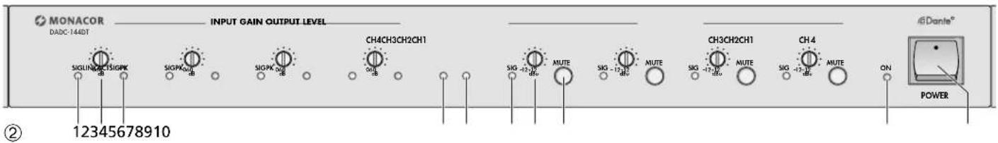
1.1 Front panel
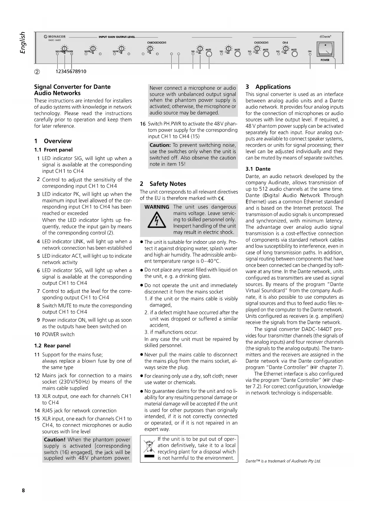
1 LED indicator SIG, will light up when a signal is available at the corresponding input CH1 to CH4
2 Control to adjust the sensitivity of the corresponding input CH1 to CH4
3 LED indicator PK, will light up when the maximum input level allowed of the corresponding input CH1 to CH4 has been reached or exceeded
When the LED indicator lights up frequently, reduce the input gain by means of the corresponding control (2).
4 LED indicator LINK, will light up when a network connection has been established
5 LED indicator ACT, will light up to indicate network activity
6 LED indicator SIG, will light up when a signal is available at the corresponding output CH1 to CH4
7 Control to adjust the level for the corresponding output CH1 to CH4
8 Switch MUTE to mute the corresponding output CH1 to CH4
9 Power indicator ON, will light up as soon as the outputs have been switched on
10 POWER switch
1.2 Rear panel
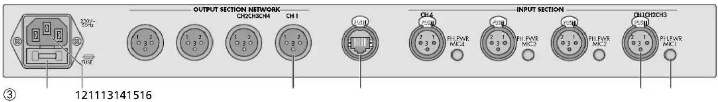
11 Support for the mains fuse; always replace a blown fuse by one of the same type
12 Mains jack for connection to a mains socket (230V/50Hz) by means of the mains cable supplied
13 XLR output, one each for channels CH1 to CH4
14 RJ45 jack for network connection
15 XLR input, one each for channels CH1 to CH4, to connect microphones or audio sources with line level
Caution! When the phantom power supply is activated [corresponding switch (16) engaged], the jack will be supplied with 48V phantom power.
Never connect a microphone or audio source with unbalanced output signal when the phantom power supply is activated; otherwise, the microphone or audio source may be damaged.
16 Switch PH.PWR to activate the 48V phantom power supply for the corresponding input CH1 to CH4 (15)
Caution: To prevent switching noise, use the switches only when the unit is switched off. Also observe the caution note in item 15!
2 Safety Notes
The unit corresponds to all relevant directives of the EU is therefore marked with €.
WARNING

The unit uses dangerous mains voltage. Leave servicing to skilled personnel only. Inexpert handling of the unit may result in electric shock.
- The unit is suitable for indoor use only. Protect it against dripping water, splash water and high air humidity. The admissible ambient temperature range is 0–40°C.
- Do not place any vessel filled with liquid on the unit, e.g. a drinking glass.
-
Do not operate the unit and immediately disconnect it from the mains socket
-
if the unit or the mains cable is visibly damaged,
- if a defect might have occurred after the unit was dropped or suffered a similar accident,
- if malfunctions occur.
In any case the unit must be repaired by skilled personnel.
- Never pull the mains cable to disconnect the mains plug from the mains socket, always seize the plug.
- For cleaning only use a dry, soft cloth; never use water or chemicals.
- No guarantee claims for the unit and no liability for any resulting personal damage or material damage will be accepted if the unit is used for other purposes than originally intended, if it is not correctly connected or operated, or if it is not repaired in an expert way.

If the unit is to be put out of operation definitively, take it to a local recycling plant for a disposal which is not harmful to the environment.
3 Applications
This signal converter is used as an interface between analog audio units and a Dante audio network. It provides four analog inputs for the connection of microphones or audio sources with line output level. If required, a 48 V phantom power supply can be activated separately for each input. Four analog outputs are available to connect speaker systems, recorders or units for signal processing; their level can be adjusted individually and they can be muted by means of separate switches.
3.1 Dante
Dante, an audio network developed by the company Audinate, allows transmission of up to 512 audio channels at the same time. Dante (Digital Audio Network Through Ethernet) uses a common Ethernet standard and is based on the Internet protocol. The transmission of audio signals is uncompressed and synchronized, with minimum latency. The advantage over analog audio signal transmission is a cost-effective connection of components via standard network cables and low susceptibility to interference, even in case of long transmission paths. In addition, signal routing between components that have once been connected can be changed by software at any time. In the Dante network, units configured as transmitters are used as signal sources. By means of the program "Dante Virtual Soundcard" from the company Audinate, it is also possible to use computers as signal sources and thus to feed audio files replayed on the computer to the Dante network. Units configured as receivers (e.g. amplifiers) receive the signals from the Dante network.
The signal converter DADC-144DT provides four transmitter channels (the signals of the analog inputs) and four receiver channels (the signals to the analog outputs). The transmitters and the receivers are assigned in the Dante network via the Dante configuration program "Dante Controller" ( chapter 7).
The Ethernet interface is also configured via the program "Dante Controller" ( chapter 7.2). For correct configuration, knowledge in network technology is indispensable.
text_image
OUTPUT SECTION NETWORK CH2CH3CH4 CH1 FUSE 1 2 3 2 3 2 3 2 3 ③ 121113141516 INPUT SECTION CH4 FUSM FH FWR MIC4 2 1 3 2 1 3 FH FWR MIC3 2 1 3 FH FWR MIC2 2 1 3 FH FWR MIC1 CH1CH2CH3 FUSM FH FWR MIC14 Setting up the Unit
The unit is designed for installation into a rack (482 mm / 19"); however, it can also be used as a tabletop unit.
4.1 Rack installation
For rack installation, screw the two mounting brackets supplied onto the right and left sides of the unit (fig. 1). In the rack, 1 rack space (= 44.45 mm) is required.
5 Connecting Units
Prior to making any connection, switch off the units to be connected.
5.1 Inputs
Connect microphones or audio sources with line signal level (e.g. CD player, preamplifier, mixer) to the input jacks INPUT SECTION (15). The jacks are designed for balanced signals. Audio sources with unbalanced signals can be connected via an XLR plug where the contacts 1 and 3 are connected with each other.
By means of the switches PH.PWR (16), individual jacks can be supplied with 48 V phantom power which some microphones (e.g. condenser microphones) require for operation. To activate the phantom power supply, engage the switch. Disengage the switch unless the audio source definitely requires phantom power.
Caution! When the phantom power supply has been activated, make sure that no microphone or audio unit with unbalanced output signal has been connected to the input; the microphone or audio unit may be damaged. To avoid switching noise, only use the switches when the unit is switched off.
5.2 Outputs
The inputs OUTPUT SECTION (13) can be used to connect units with line level inputs such as amplifiers, active speakers, mixers, recorders or units for signal processing. The jacks provide balanced signals.
5.3 Network
For connection to a Dante network, connect the RJ45 jack NETWORK (14) to an Ethernet switch which supports at least Fast Ethernet (100 MBits/s Ethernet).
The LED indicator LINK (4) will light up when a network connection has been established; the LED indicator ACT (5) will light up to indicate network activity.
5.4 Power supply
Finally, connect the mains cable supplied to the mains jack (12) and then to a mains socket (230V/50Hz).
6 Operation
1) Prior to initial switch-on, use a small screw-driver to set the controls for sensitivity adjustment INPUT GAIN (2) and the controls OUTPUT LEVEL (7) to the left stop.
2) First switch on the signal sources connected to the inputs (15), then switch on the signal converter DADC-144DT with the POWER switch (10).
After switch-on, the outputs will be switched on with a delay of a few seconds; then the LED indicator ON (9) will light up.
3) Use the controls INPUT GAIN (2) to adjust the sensitivity of the inputs in such a way that the LED indicator SIG (1) will light with typical input signals and the LED indicator PK (3) will only light up with signal peaks. The LED indicator PK will light up continuously when the input is overloaded. In this case, reduce the input sensitivity or the level of the signal source accordingly.
4) Use the controls OUTPUT LEVEL (7) to match the signal level of the outputs to the input sensitivity of the units connected. The LED indicators SIG (6) will light up when a signal is available at the output.
5) Use the switches MUTE (8) to mute the corresponding outputs (engage the button). To unmute an output, disengage the corresponding button.
6) After operation, first switch off the units connected to the outputs, then the signal converter DADC-144DT and finally the audio sources connected to the inputs.
7 Configuration of the Dante Network
The signal converter DADC-144DT is set up as transmitter and receiver in the Dante network by means of the program "Dante Controller", available as a free download on the website of the company Audinate. The settings made via the program will be saved in the corresponding units of the Dante network so that the program is only required for network configuration but not for normal operation. The following system requirements apply to the computer on which the program "Dante Controller" is to be executed:
| Component | Minimum requirements |
| Processor | 1 GHz |
| RAM | 512 MB |
| Network | Standard Ethernet interface(100 Mbit/s or Gigabit) or wireless LAN(WiFi) interface |
| Operating system | Windows 7 (SP1 or higher), 8.1 or 10Note: Both UTF-8 and Unicode will be supported, except for host names and names of units; the DNS standard will not support Unicode for them. |
| Mac OS X 10.11.6, 10.12.6 or 10.13Note: Intel architecture only; PPC architecture will not be supported. |
Windows is a registered trademark of Microsoft Corporation in the USA and other countries.
Mac OS is a registered trademark of Apple Inc. in the USA and other countries.
7.1 Installing the "Dante Controller"
To install the program from the Audinate website:
1) Call up the following Internet address: https://www.audinate.com/products/software/dante-controller
2) Select the operating system.
3) Click the button with the version of the Dante controller.
4) Log in or create an account.
5) Download the software.
6) Install the software.
7.2 Configuration of the unit with the Dante Controller
1) Start the Dante Controller.
2) Wait for the signal converter DADC-144DT and the units to which it is to be connected to appear in the matrix.
Note: If the signal converter DADC-144DT or a connection partner fails to appear in the list, the reason may be that the unit
– has not been switched on,
– is in a different subnet,
- is not able to synchronize with the other Dante units.
However, if one of the two last-mentioned reasons applies, the Dante unit should at least appear under the tab "Device Info" or "Clock Status" in the network view. A fast solution of this problem may be to switch the unit off and on or to disconnect and re-establish the connection to the network switch. For further information please refer to the user manual of the Dante Controller from Audinate.
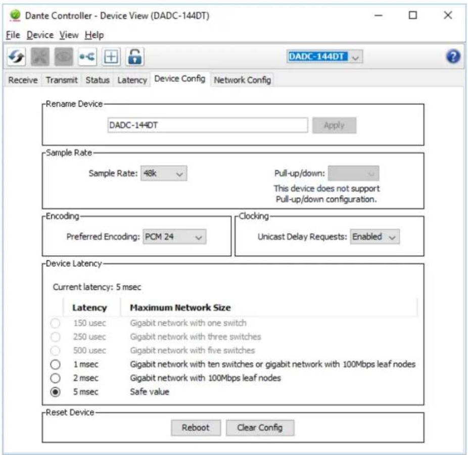
3) In the menu bar of the Dante Controller, select "Device / Device View" or use the shortcut Ctrl+D. The Device View window will open.
4) Select "DADC-144DT" in the bar of the drop-down menu appearing beneath the menu bar.
5) The third bar can be used to indicate information on the unit and to make settings. Select the tab "Device Config" (see fig. 4).
6) Adjust the "Sample Rate" to the desired connection partner or set a different common sample rate for both units, if required.
7) In the field "Rename Device", the name used for the unit in the Dante network can be changed (e.g. to a specific name referring to the place of installation). Click "Apply" to confirm the change.
8) Use the tab "Network Config" to change the network settings for the Dante interface of DADC-144DT, if required.
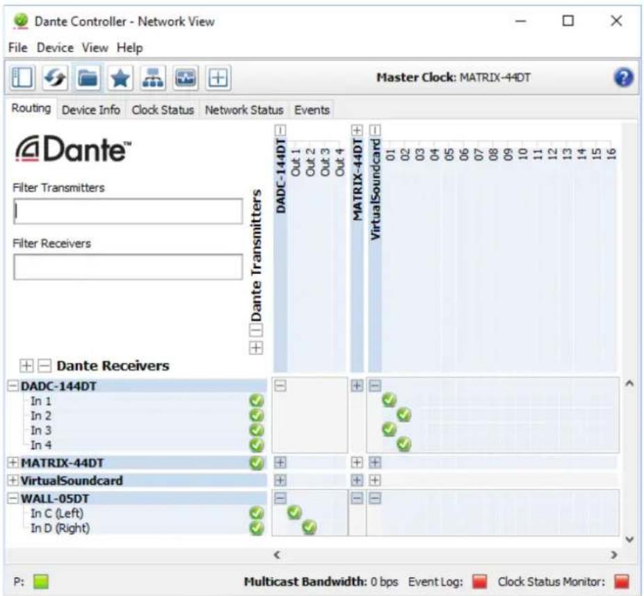
7.3 Routing with the Dante Controller
To assign the input signals and output signals of the corresponding units:
1) Under "Routing" in the window "Network View", click to open the channels of the desired unit under "Dante Transmitters" and the channels of the desired connection partner under "Dante Receivers" (see fig. 5).
2) Navigate from the column of the Dante transmit channel to the line of the desired Dante receive channel and click the field at the intersection point.
3) Wait for the field to show a green circle with a white check mark √.
Repeat the steps for additional connections.
Note: The transmitting channels of a DADC-144DT cannot be connected to the reception channels of the same unit.
An English user guide for the Dante Controller is available for download on the Audinate website:
https://www.audinate.com/resources/technical-documentation
8 Specifications
Inputs CH1-CH4
Sensitivity: 5.7 mV–2.3 V
Impedance: 5.3kΩ
Connection: ..... XLR, balanced
Phantom power: . . . 48 V, can be activated separately for each input
Outputs CH1-CH4
Max. voltage: ..... 2.3 V
Impedance: 200Ω
Connection: ..... XLR, balanced
Dante
Input channels: ..... 4
Output channels: . . . 4
Resolution: ..... 16–32 bit
Sampling rate: ..... 44.1–96 kHz
Data interface: ..... Ethernet, EtherCon jack RJ 45
Frequency range: .... 20–20 000 Hz
THD: .... < 0.005 %
S/Nratio: .... > 90 dB
Ambient temperature: 0–40°C
Power supply
Mains voltage: ..... 230V/50Hz
Power consumption:.15VA max.
Dimensions
Width
(with brackets): ..... 434 mm (482 mm)
Height: 44.5 mm (1 RS)
Depth: 238mm
Weight: 3.3 kg
Pin configuration
Inputs:

| 1 Ground | |
| 2 | Signal+, +48V phantom power (can be activated) |
| 3 | Signal-, +48V phantom power (can be activated) |
Outputs:
| 1 Ground |
| 2 Signal + |
| 3 Signal - |
Subject to technical modification.
text_image
Dante Controller - Device View (DADC-144DT) File Device View Help Receive Transmit Status Latency Device Config Network Config Rename Device DADC-144DT Apply Sample Rate Sample Rate: 48k Pull-up/down: This device does not support Pull-up/down configuration. Encoding Preferred Encoding: PCM 24 Clocking Unicast Delay Requests: Enabled Device Latency Current latency: 5 msec Latency Maximum Network Size 150 usec Gigabit network with one switch 250 usec Gigabit network with three switches 500 usec Gigabit network with five switches 1 msec Gigabit network with ten switches or gigabit network with 100Mbps leaf nodes 2 msec Gigabit network with 100Mbps leaf nodes 5 msec Safe value Reset Device Reboot Clear Config④ Device View of DADC-144DT

text_image
Dante Controller - Network View File Device View Help Master Clock: MATRIX-44DT Routing Device Info Clock Status Network Status Events Dante™ Filter Transmitters Filter Receivers Dante Receivers DADC-144DT In 1 In 2 In 3 In 4 MATRIX-44DT VirtualSoundcard WALL-05DT In C (Left) In D (Right) MATRIX-44DT VirtualSoundcard DADC-144DT Out 1 Out 2 Out 3 Out 4 01 02 03 04 05 06 07 08 09 10 11 12 13 14 15 16 P: Multicast Bandwidth: 0 bps Event Log: Clock Status Monitor:⑤ Routing: "VirtualSoundcard" "DADC-144DT" and "DADC-144DT" "WALL-05DT"
text_image
MONACOR DAC-144DT INPUT GAIN OUTPUT LEVEL SIGLIN 0.05 SIGPK SIGPK 0.05 SIGPK 0.05 CH4CH3CH2CH1 SIG -12.12 dB+ MUTE SIG -12.12 dB+ MUTE SIG -12.12 dB+ MUTE SIG -12.12 dB+ MUTE ON @Dante® POWER ② 12345678910https://www.audinate.com/resources/technical-documentation
text_image
Dante Controller - Device View (DADC-144DT) File Device View Help Receive Transmit Status Latency Device Config Network Config Rename Device DADC-144DT Apply Sample Rate Sample Rate: 48k Pull-up/down: This device does not support Pull-up/down configuration. Encoding Preferred Encoding: PCM 24 Clocking Unicast Delay Requests: Enabled Device Latency Current latency: 5 msec Latency Maximum Network Size 150 usec Gigabit network with one switch 250 usec Gigabit network with three switches 500 usec Gigabit network with five switches 1 msec Gigabit network with ten switches or gigabit network with 100Mbps leaf nodes 2 msec Gigabit network with 100Mbps leaf nodes 5 msec Safe value Reset Device Reboot Clear Config④ Device View du DADC-144DT

text_image
Dante Controller - Network View File Device View Help Master Clock: MATRIX-44DT Routing Device Info Clock Status Network Status Events Dante™ Filter Transmitters Filter Receivers Dante Receivers DADC-144DT In 1 In 2 In 3 In 4 MATRIX-44DT VirtualSoundcard WALL-05DT In C (Left) In D (Right) MATRIX-44DT VirtualSoundcard DADC-144DT Out 1 Out 2 Out 3 Out 4 01 02 03 04 05 06 07 08 09 10 11 12 13 14 15 16 P: Multicast Bandwidth: 0 bps Event Log: Clock Status Monitor:⑤ Routage: «VirtualSoundcard» ◆ «DADC-144DT» et «DADC-144DT» ◆ «WALL-05DT»
https://www.audinate.com/resources/technical-documentation
8 Specifiche
Ingressi CH1–CH4
text_image
Dante Controller - Device View (DADC-144DT) File Device View Help Receive Transmit Status Latency Device Config Network Config DADC-144DT Rename Device DADC-144DT Apply Sample Rate Sample Rate: 48k Pull-up/down: This device does not support Pull-up/down configuration. Encoding Preferred Encoding: PCM 24 Clocking Unicast Delay Requests: Enabled Device Latency Current latency: 5 msec Latency Maximum Network Size 150 usec Gigabit network with one switch 250 usec Gigabit network with three switches 500 usec Gigabit network with five switches 1 msec Gigabit network with ten switches or gigabit network with 100Mbps leaf nodes 2 msec Gigabit network with 100Mbps leaf nodes 5 msec Safe value Reset Device Reboot Clear Config④ Device View del DADC-144DT
text_image
Dante Controller - Network View File Device View Help Master Clock: MATRIX-44DT Routing Device Info Clock Status Network Status Events Dante™ Filter Transmitters Filter Receivers Dante Receivers DADC-144DT In 1 In 2 In 3 In 4 MATRIX-44DT VirtualSoundcard WALL-05DT In C (Left) In D (Right) MATRIX-44DT VirtualSoundcard DADC-144DT Out 1 Out 2 Out 3 Out 4 01 02 03 04 05 06 07 08 09 10 11 12 13 14 15 16 P: Multicast Bandwidth: 0 bps Event Log: Clock Status Monitor:⑤ Routing: "VirtualSoundcard" ♦ "DADC-144DT" e "DADC-144DT" ♦ "WALL-05DT"