
EH875BE15E - Cooker SIEMENS - Free user manual and instructions
Find the device manual for free EH875BE15E SIEMENS in PDF.
| Product Type | Cooktop with integrated extractor |
| Brand | Siemens |
| Model | EH875BE15E |
| Dimensions (W x D x H) | Approx. 900 x 520 x 80 mm (estimate) |
| Weight | ≤ 25 kg |
| Power Supply | 230 V, 50/60 Hz, connection 1N, 2N, 3N or 2L/2N |
| Maximum Power | Approx. 7.4 kW (estimate) |
| Number of Cooking Zones | 4 (estimate) |
| Cooking Type | Induction (estimate) |
| Exhaust Modes | External extraction or air recirculation |
| Included Filters | Grease filter, odor filter, acoustic filter |
| Max. Airflow | Not specified (estimate 600 m³/h) |
| Max. Noise Level | Not specified (estimate 65 dB) |
| Safety Distance (electronic implant) | ≥ 10 cm (permanent magnets) |
| Protection Class | I |
| Installation | Built-in, worktop supporting 60 kg |
| Filter Maintenance | Clean grease filter regularly, replace odor and acoustic filters |
| Repairability | Spare parts available via Siemens after-sales service |
| Delivery Contents | Appliance, fixing bars, seals, recycling adapter, filters, installation manual |
| Warranty | 2 years (Siemens standard) |
Frequently Asked Questions - EH875BE15E SIEMENS
User questions about EH875BE15E SIEMENS
0 question about this device. Answer the ones you know or ask your own.
Ask a new question about this device
Download the instructions for your Cooker in PDF format for free! Find your manual EH875BE15E - SIEMENS and take your electronic device back in hand. On this page are published all the documents necessary for the use of your device. EH875BE15E by SIEMENS.
USER MANUAL EH875BE15E SIEMENS
m = 311
18
13/14
20
22
m = 311 ;
24
25
26
27
28
29
m = 311
31
m = 311
33
35
36
38
37
40
42
43
45
44
47
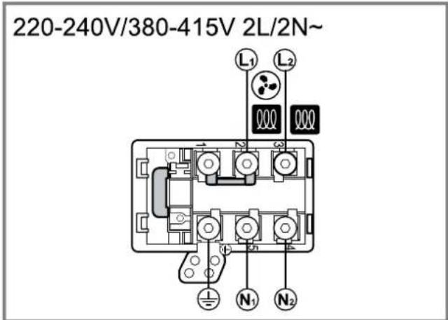
220-240V/380-415V 2L/2N~
49
220-240V/380-415V 3N~
50
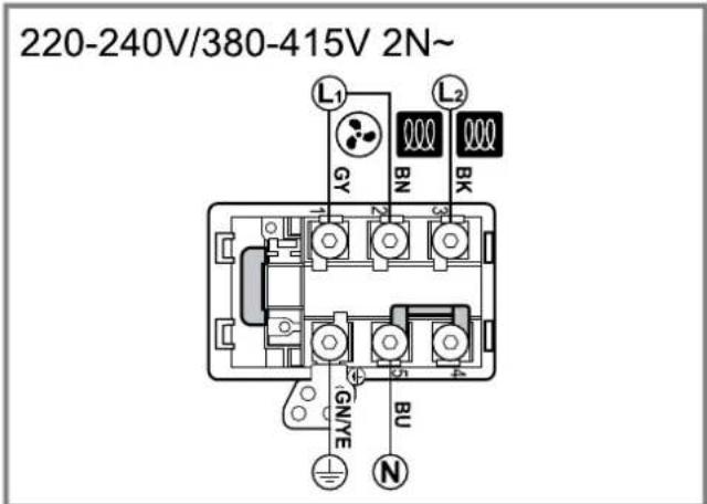
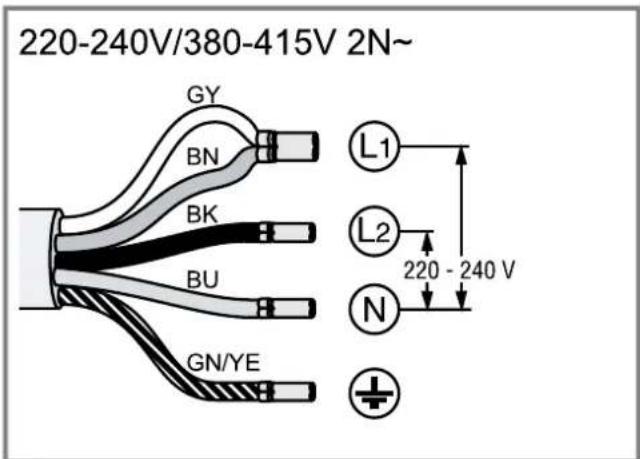
220-240V/380-415V 2N~
51
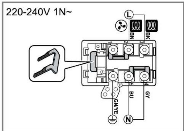
220-240V 1N~
52
es
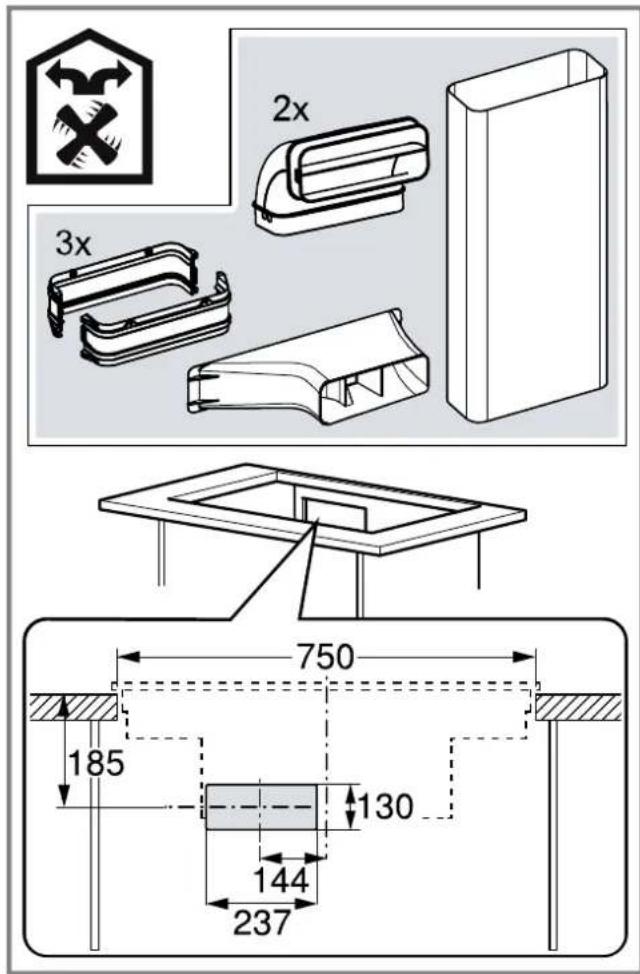
After unpacking all parts, check for any damage in transit and completeness of the delivery.
$$ \rightarrow F i g. 1 $$
QR code for the installation video
This is were you will find the QR code for the installation video. Fig. 2
Appliance dimensions
You will find the dimensions of the appliance here Fig. 3
Installation dimensions for flat duct bends
This is where you can find an overview of the installation dimensions for the flat duct bends.
Side view:
$$ \rightarrow \text {F i g .} 4, \rightarrow \text {F i g .} 5, \rightarrow \text {F i g .} 6 $$
Front view:
$$ \rightarrow F i g. \mathbf {7} $$
Installation variants
This is where you can find an overview of the different installation variants.
Odour filter and adapter for circulating-air mode:
$$ \rightarrow F i g. \quad 8 $$
Odour filter, diffuser and seal for circulating-air mode: Fig. 9
Acoustics filter and seal for air extraction mode: Fig. 10
Note: Channels suitable for installation can be obtained from customer service, our website or from specialist retailers.
Safety clearances
Comply with the safety clearances for the appliance. Clearances to the overflow container:
→Fig. 11
Position of the overflow container: Fig. 12
The performance is optimal at a clearance of 50mm between the unit back panel and the wall. The performance is reduced at a smaller clearance.
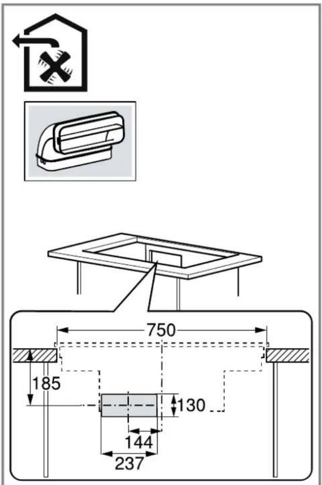
Fig. 13
Observe the safety clearances for the worktop cutout.
Do not place any objects in the drawer which exceed the maximum height of the drawer. The objects may come into contact with the base of the appliance and thus disrupt the functions.
→Fig. 14

General information
- Read this instruction manual carefully.
Only a licensed expert may connect the appliance. - Switch off the power supply before carrying out any work.
- Never use this appliance in boats or in vehicles.
- Follow the worktop manufacturer's recommendations.
Safe installation
Follow these safety instructions when installing the appliance.
The appliance can only be used safely if it is correctly installed according to the safety instructions. The installer is responsible for ensuring that the appliance works perfectly at its installation location.
WARNING - Danger: Magnetism!
The appliance contains permanent magnets. They may affect electronic implants, e.g. pacemakers or insulin pumps.
- Persons with electronic implants must stand at least 10cm away from the appliance.
WARNING - Risk of poisoning!
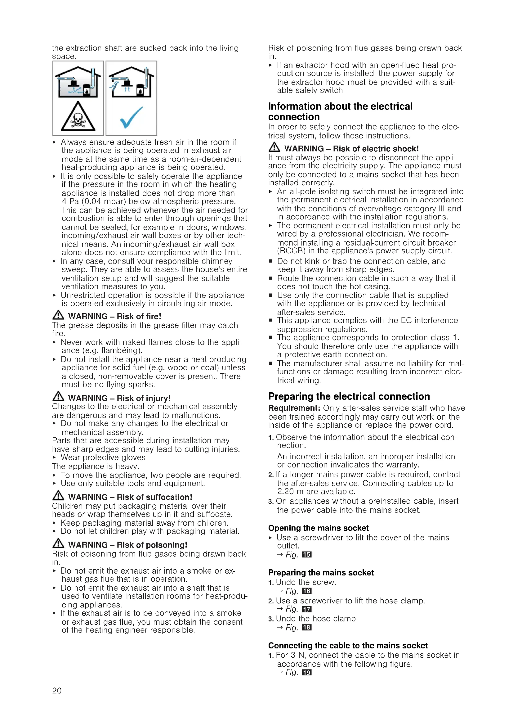
Risk of poisoning from flue gases being drawn back in. Room-air-dependent heat-producing appliances (e.g. gas, oil, wood or coal-operated heaters, continuous flow heaters or water heaters) obtain combustion air from the room in which they are installed and discharge the exhaust gases into the open through an exhaust gas system (e.g. a chimney).
With the extractor hood switched on, air is extracted from the kitchen and the adjacent rooms. Without an adequate supply of air, the air pressure falls below atmospheric pressure. Toxic gases from the flue or
the extraction shaft are sucked back into the living space.
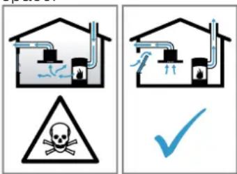
Always ensure adequate fresh air in the room if the appliance is being operated in exhaust air mode at the same time as a room-air-dependent heat-producing appliance is being operated.
It is only possible to safely operate the appliance if the pressure in the room in which the heating appliance is installed does not drop more than 4Pa (0.04 mbar) below atmospheric pressure. This can be achieved whenever the air needed for combustion is able to enter through openings that cannot be sealed, for example in doors, windows, incoming/exhaust air wall boxes or by other technical means. An incoming/exhaust air wall box alone does not ensure compliance with the limit.
In any case, consult your responsible chimney sweep. They are able to assess the house's entire ventilation setup and will suggest the suitable ventilation measures to you.
Unrestricted operation is possible if the appliance is operated exclusively in circulating-air mode.
WARNING - Risk of fire!
The grease deposits in the grease filter may catch fire.
- Never work with naked flames close to the appliance (e.g. flambeing).
- Do not install the appliance near a heat-producing appliance for solid fuel (e.g. wood or coal) unless a closed, non-removable cover is present. There must be no flying sparks.
WARNING - Risk of injury!
Changes to the electrical or mechanical assembly are dangerous and may lead to malfunctions.
- Do not make any changes to the electrical or mechanical assembly.
Parts that are accessible during installation may have sharp edges and may lead to cutting injuries.
Wear protective gloves
The appliance is heavy.
To move the appliance, two people are required.
- Use only suitable tools and equipment.
WARNING - Risk of suffocation!
Children may put packaging material over their heads or wrap themselves up in it and suffocate.
- Keep packaging material away from children.
- Do not let children play with packaging material.
WARNING - Risk of poisoning!
Risk of poisoning from flue gases being drawn back in.
- Do not emit the exhaust air into a smoke or exhaust gas flue that is in operation.
- Do not emit the exhaust air into a shaft that is used to ventilate installation rooms for heat-producing appliances.
If the exhaust air is to be conveyed into a smoke or exhaust gas flue, you must obtain the consent of the heating engineer responsible.
Risk of poisoning from flue gases being drawn back in.
If an extractor hood with an open-flued heat production source is installed, the power supply for the extractor hood must be provided with a suitable safety switch.
Information about the electrical connection
In order to safely connect the appliance to the electrical system, follow these instructions.
WARNING - Risk of electric shock!
It must always be possible to disconnect the appliance from the electricity supply. The appliance must only be connected to a mains socket that has been installed correctly.
An all-pole isolating switch must be integrated into the permanent electrical installation in accordance with the conditions of overvoltage category III and in accordance with the installation regulations.
The permanent electrical installation must only be wired by a professional electrician. We recommend installing a residual-current circuit breaker (RCCB) in the appliance's power supply circuit.
- Do not kink or trap the connection cable, and keep it away from sharp edges.
- Route the connection cable in such a way that it does not touch the hot casing.
- Use only the connection cable that is supplied with the appliance or is provided by technical after-sales service.
This appliance complies with the EC interference suppression regulations.
- The appliance corresponds to protection class 1. You should therefore only use the appliance with a protective earth connection.
The manufacturer shall assume no liability for malfunctions or damage resulting from incorrect electrical wiring.
Preparing the electrical connection
Requirement: Only after-sales service staff who have been trained accordingly may carry out work on the inside of the appliance or replace the power cord.
- Observe the information about the electrical connection.
An incorrect installation, an improper installation or connection invalidates the warranty. - If a longer mains power cable is required, contact the after-sales service. Connecting cables up to 2.20m are available.
- On appliances without a preinstalled cable, insert the power cable into the mains socket.
Opening the mains socket
- Use a screwdriver to lift the cover of the mains outlet.
$$ \rightarrow \text {F i g .} 1 5 $$
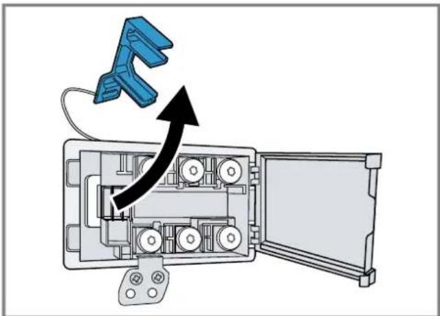
Preparing the mains socket
- Undo the screw.
$$ \rightarrow \text {F i g .} 1 6 $$
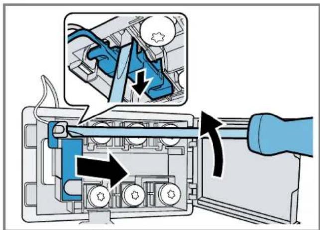
- Use a screwdriver to lift the hose clamp.
$$ \rightarrow \text {F i g .} \quad 1 7 $$
- Undo the hose clamp.
$$ \rightarrow \text {F i q .} 1 8 $$
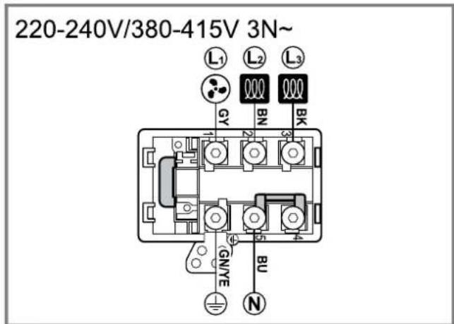
Connecting the cable to the mains socket
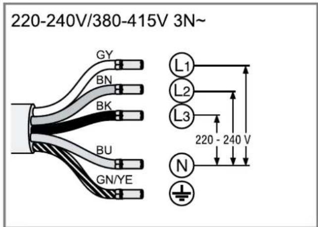
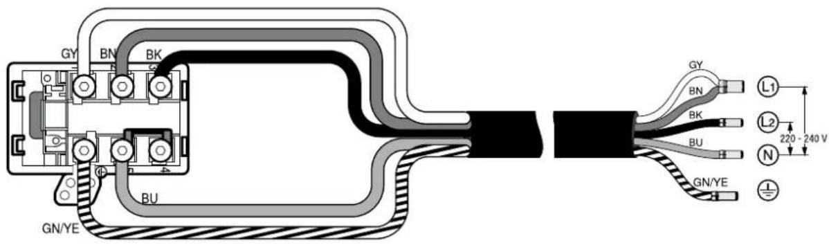
- For 3N connect the cable to the mains socket in accordance with the following figure.
$$ \rightarrow \text {F i g .} \quad 1 9 $$
- For 2N connect the cable to the mains socket in accordance with the following figure. Fig. 20
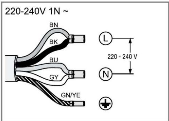
- For 1 N, connect the cable to the mains socket in accordance with the following figure. Fig.21
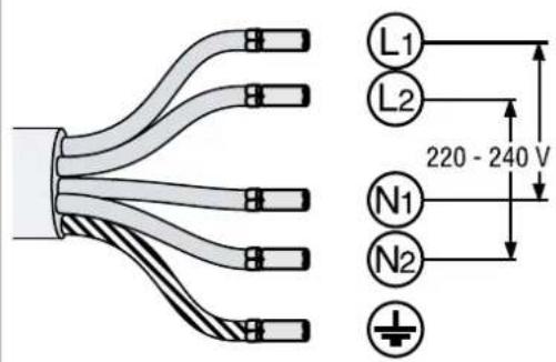
- For 2L / 2N connect the cable to the mains socket in accordance with the following figure. Fig. 22
-
Note the colours of the cables.
-
BN: Brown
- BU: Blue
- GN/YE: Yellow and green
- BK: Black
-
GY: Grey
-
If required, install the enclosed copper bridges in accordance with the connection diagram.
- Connect the cables and then tighten the screws of the mains socket.
- For a 1N^ or 2L/2N connection in accordance with the connection diagram, 1 corresponds to the fan motor.
- For a 2N^ / 3N^ connection, phase L1 (grey) corresponds to the fan motor.
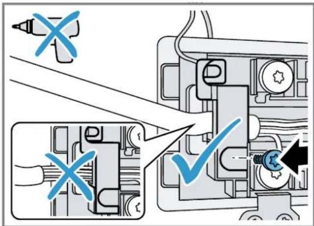
Secure the cable in the mains socket
- Use the hose clamp to secure the power cord.
-
Tighten the screw at the correct position.
-
Do not use a cordless screwdriver.
$$ \rightarrow \text {F i g .} 2 3 $$
- To facilitate closing the mains socket, arrange the cables in the central area of the mains socket.
- Close the cover of the mains socket.
Instructions for the exhaust air pipe
The appliance manufacturer does not provide any warranty for faults attributable to the pipeline.
Use a short, straight exhaust air pipe with as large a pipe diameter as possible.
- Long, rough exhaust air pipes, many pipe bends or small pipe diameters reduce the suction power and increase the fan noise.
- Use an exhaust pipe that is made of non-combustible material.
- To prevent condensate from returning, fit the exhaust pipe with a 1^ gradient from the appliance.
Flat ducts
Use flat ducts with an inner cross-section that corresponds to the diameter of the round pipes:
- Diameter of 150~mm corresponds to approx. 177~cm^2
Use sealing strips for different pipe diameters. - Do not use any flat ducts with sharp bends.
Round pipes
Round pipes with an inner diameter of 150~mm
Instructions for the air extraction mode
For air extraction mode, a one-way flap should be installed.
Notes
If a one-way flap is not included with the appliance, one can be ordered from a specialist retailer.
If the exhaust air is conveyed through the external wall, a telescopic duct should be used.
Checking the units
- Check whether the fitted unit is level and has sufficient load-bearing capacity.
The maximum weight of the appliance is approx. 25kg
The worktop into which you are fitting the appliance must be able to withstand loads of approx. 60kg
- Ensure that the stability of the fitted unit is also guaranteed following cut-out work.
-
Use suitable substructures to ensure the load-bearing capacity and the stability, particularly in the case of thin worktops.
-
Take the appliance weight, including additional load, into consideration.
-
Use heat-resistant and moisture-resistant reinforcement material.
-
Ensure that the fitted unit is heat-resistant up to 90^ .
- Do not support any other appliances, e.g. ovens, refrigerators, dishwashers or washing machines.
- Only check that the appliance is level once it has been installed in the installation opening.
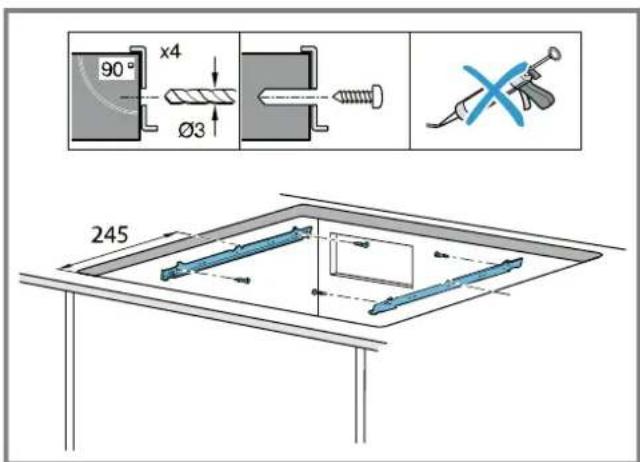
Installing the support rails
Install the support rails in the unit.
-
Glue the support rails to the stone worktop. For stone worktops, use a heat-resistant adhesive suitable for gluing metal and stone.
-
Do not use silicone for sealing.
$$ \rightarrow F i g. \quad 2 4 $$
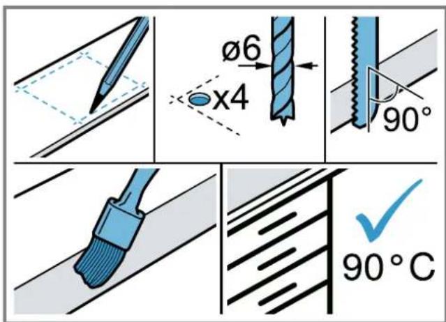
Preparing the units
Requirement: The fitted units must be heat-resistant up to 90^
- Mark the unit cut-out in accordance with the installation diagram.
$$ \rightarrow \text {F i g .} \tag {14} $$
- Drill four holes with a diameter of 6mm
$$ \rightarrow \text {F i g .} \quad 2 5 $$
- Ensure that the angle of the cut surface to the worktop is 90^ .
$$ \rightarrow \text {F i g .} 2 5 $$
Observing the minimum clearances when installing above a drawer
$$ \rightarrow \text {F i g .} \quad 1 1 $$
$$ \rightarrow \text {F i g .} 1 2 $$
- When removing the overflow container on integrated appliances, take the minimum clearances into consideration.
- Observe the position of the overflow container.
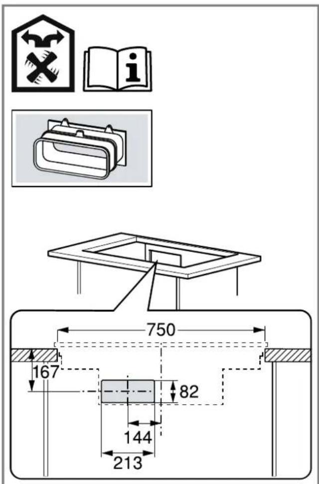
Preparing the unit for circulating-air mode with the adapter
Note: We do not recommend to install on a non-thermally insulated outer wall or above a cold floor ( ≥ 0.5W / m^2 C)
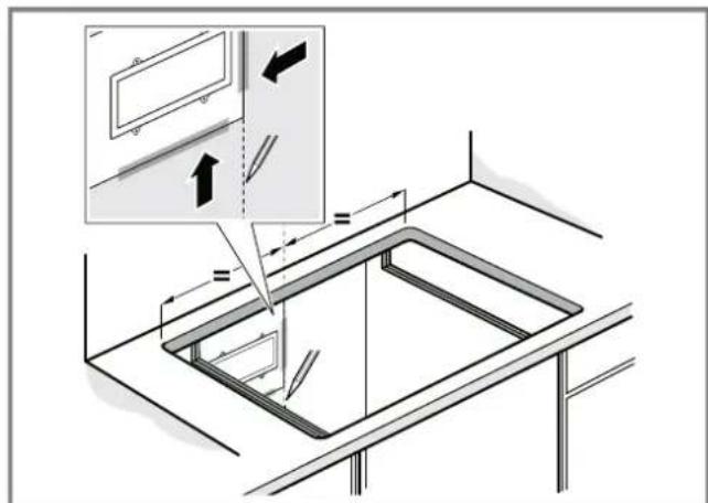
- Observe the relevant dimensions when combining with the adapter for the cut-out in the back wall. Fig. 26
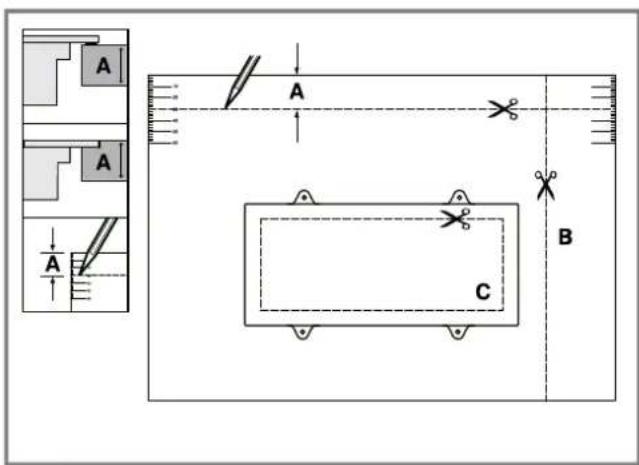
- Measure the thickness of the worktop. Transfer the measurement to the template and draw a line that corresponds to it.
$$ \rightarrow \text {F i g .} 2 7 $$
- Cut the template along the marked line for worktop thickness A, the cut centre line B and the reference line to the inner air outlet C.
- Mark the centre of the cut-out in the worktop as the centre line on the back panel of the unit.
$$ \rightarrow \text {F i g .} 2 8 $$
- Align the template to the centre line of the back panel of the unit and to the lower edge of the work surface.
- Use the template to make the cut-out in the back panel.
- After making the cut-outs, remove any shavings.
- Seal the cut surfaces so that they are heat-resistant and waterproof. Fig. 25
Ventilation
-
In circulating-air mode, establish an air outlet in the unit's plinth.
-
Provide a minimum air outlet cross-section of approx. 400~cm^2
-
To keep the draught and noise low, ensure that the outlet opening in the base panel is as large as possible.
-
To guarantee that the appliance works correctly, ventilate the hob appropriately via an air outlet with a minimum cross-section of 200~cm^2 in the base unit.
Installing an appliance featuring circulating-air mode with adapter
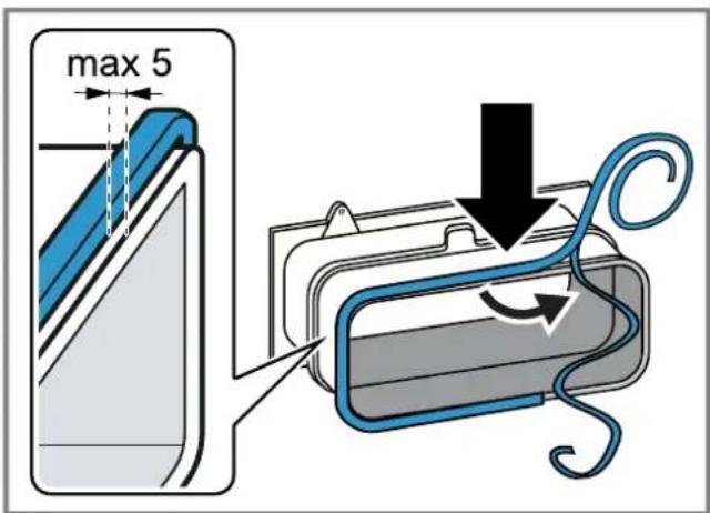
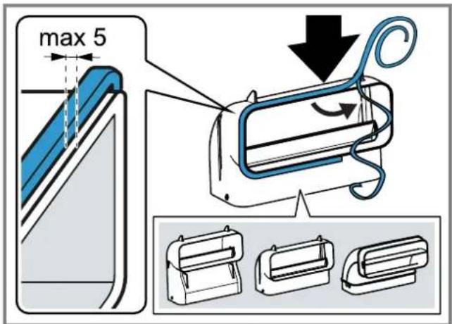
Attaching the seal to the adapter
- Attach the seal to the adapter with max. 5mm to the edge.
Fig. 29
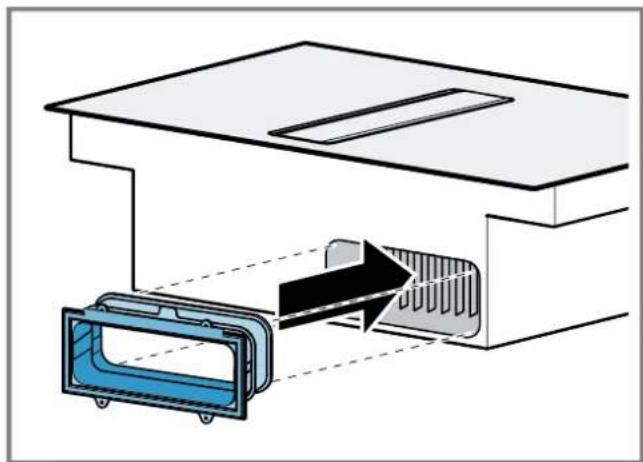
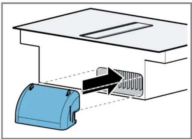
Attaching the adapter
- Clean and degrease the adhesive surface around the cut-out in the unit's back panel.
-
Insert the adapter into the outlet opening on the rear of the hob. Fig. 30
-
Remove the adhesive tape's protective film from the adapter.
Fig. 31
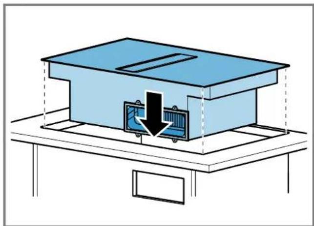
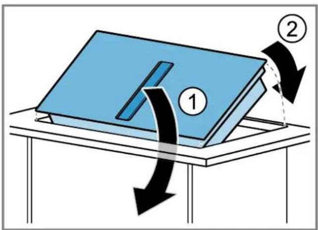
Inserting the appliance into the worktop cut-out
- Ensure that the connection cable is connected to the appliance.
- Carefully insert the appliance into the worktop cutout.
Fig. 32
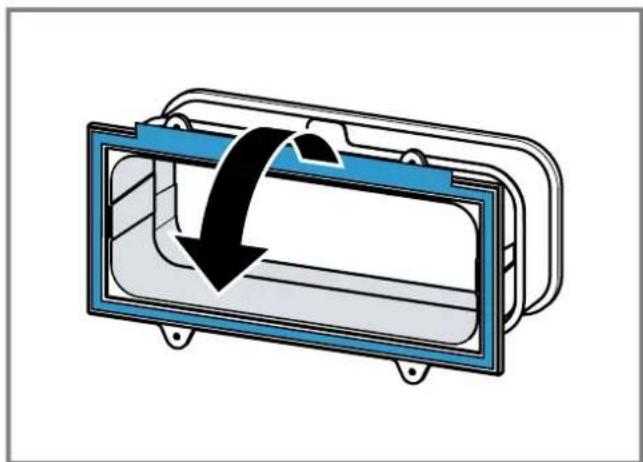
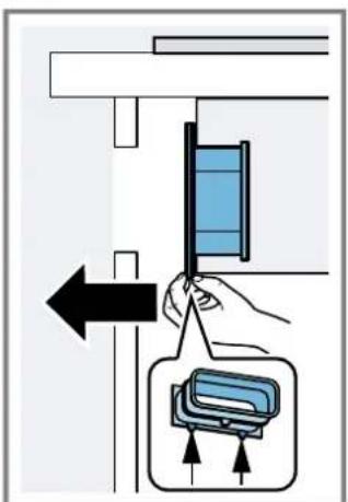
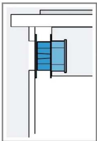
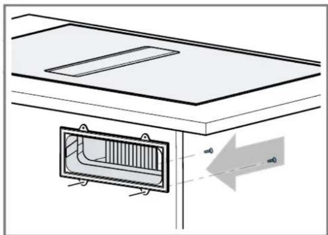
Securing the adapter
- Hold the adapter at the central holder and use the side holders to slide it towards the unit's back panel in the base unit, then affix it.
→Fig. 38 - If required, also use screws to secure it.
Fig. 34
Preparing the unit for circulating-air mode with a circulating-air duct
- If required, remove the unit's back wall.
- Observe the relevant dimensions when combining with the flat duct elbow for the cut-out in the back wall.
Fig. 35
-
In circulating-air mode, establish an air outlet in the unit's plinth.
-
Provide a minimum air outlet cross-section of approx. 400~cm^2
-
To keep the draught and noise low, ensure that the outlet opening in the base panel is as large as possible.
-
To guarantee that the appliance works correctly, ventilate the hob appropriately via an air outlet with a minimum cross-section of 200~cm^2 in the base unit.
-
After making the cut-outs, remove any shavings.
-
Seal the cut surfaces so that they are heat-resistant and waterproof.
Fig. 25
Installing the appliance for air recirculation mode with circulating-air duct
- For circulating-air mode, use the seal, the circulating-air duct, the diffuser and the odour filter.
- Observe the dimensions for the different flat duct bends. Page 19
Securing the seal
- Secure the enclosed seal on the flat duct elbow at a maximum of 5mm from the edge.
Fig. 36
Inserting the flat duct elbow
- Insert the flat duct elbow into the outlet opening on the rear of the appliance.
Fig. 37
Inserting the appliance into the worktop cut-out
- Ensure that the connection cable is connected to the appliance.
- Carefully insert the appliance into the worktop cutout.
Fig. 38
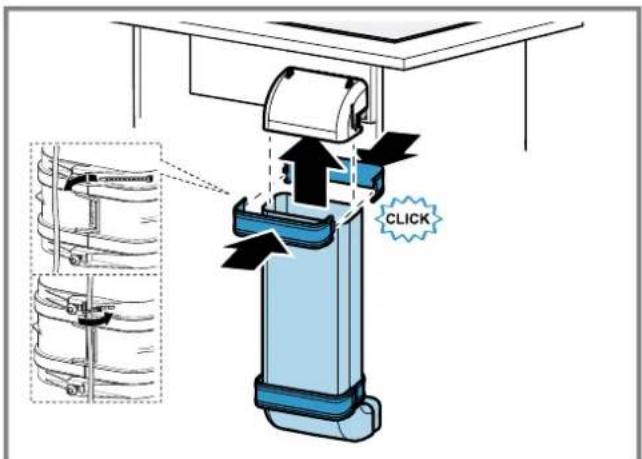
Establishing the pipework between the appliance and the diffuser
-
Connect the components of the circulating-air duct to each other.
-
Secure the flat duct pipe connector by engaging it in place.
- For an additional fixing, screw the flat duct pipe connector together using 4 × PT 4 × 8 ~mm screws for plastic.
Fig. 39
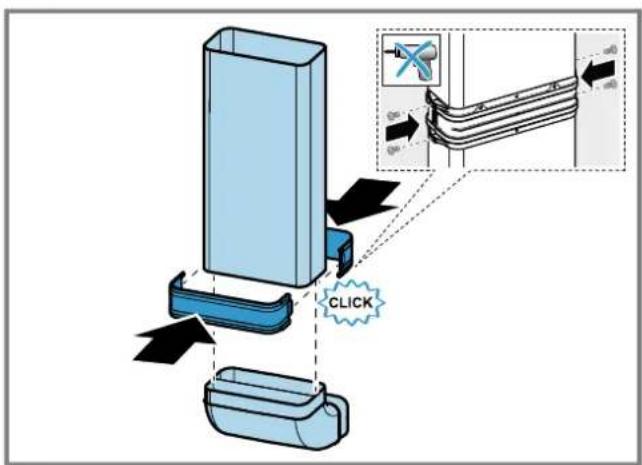
- Connect the circulating-air duct to the flat duct elbow on the rear of the hob.
Fig. 40
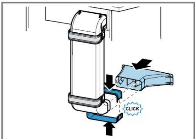
- Connect the diffuser to the circulating-air duct.
Fig. 41
Preparing the unit for air extraction mode
- If required, remove the unit's back wall.
- Observe the relevant dimensions when combining with a flat duct elbow for the cut-out in the back wall.
Fig. 42
- After making the cut-outs, remove any shavings.
- Seal the cut surfaces so that they are heat-resistant and waterproof.
Fig. 25
Install the appliance for air extraction mode
- For air extraction mode, use the seal and the acoustics filters.
- Observe the instructions for the exhaust air pipe. Page 21
Securing the seal
- Secure the enclosed seal on the flat duct elbow at a maximum of 5mm from the edge.
→Fig. 36
Establishing the piping
- Insert the flat duct elbow into the outlet opening on the rear of the appliance.
Fig. 37 - If required, install additional piping elements.
Inserting the appliance into the worktop cut-out
- Ensure that the connection cable is connected to the appliance.
- Carefully insert the appliance into the worktop cutout.
Fig. 38
Connecting the exhaust air pipe
- Secure the exhaust air pipe to the flat duct bend.
- Establish the connection to the exhaust air opening.
- Seal the joints appropriately.
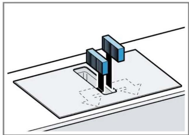
Inserting filters
Note: For circulating-air mode, insert the odour filters.
For air extraction mode, insert the acoustics filters.
- Observe the filters' air flow direction.
- Insert two of the filters into the left and right of the appliance, and slide them forwards.
$$ \rightarrow F i g. \quad 4 8 $$
$$ \rightarrow \text {F i g .} 4 4 $$
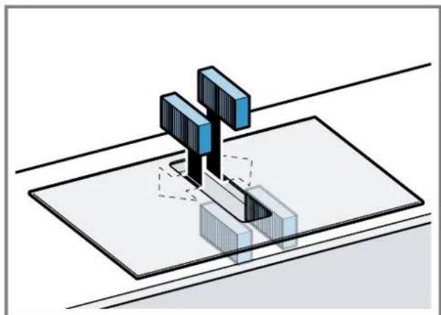
- Insert the other filters into the left and right of the appliance.
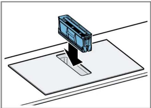
Inserting grease filters
- Insert the grease filter.
Fig. 45
Establishing the connection to the power supply
- Observe the connection data on the rating plate.
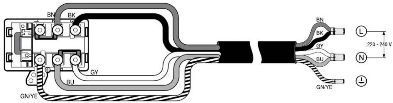
- For 3N connect the cable to the mains socket in accordance with the figure.
$$ \rightarrow \text {F i g .} 4 6 $$
- For 2N connect the cable to the mains socket in accordance with the figure.
$$ \rightarrow \text {F i g .} 4 7 $$
- For 1 N, connect the cable to the mains socket in accordance with the figure.
$$ \rightarrow \text {F i g .} 4 8 $$
- For 2L / 2N connect the cable to the mains socket in accordance with the figure.
$$ \rightarrow \text {F i g .} 4 9 $$
-
Note the colours of the cables.
-
BN: Brown
- BU: Blue
- GN/YE: Yellow and green
- BK: Black
-
GY: Grey
-
If required, arrange the supplied wire end ferrules differently depending on the type of connection.
-
To connect two cables, if required, use a wire end ferrule.
-
Shorten the wires.
- Remove the insulation.
Checking the function
- Switch on the appliance.
- If 0408 E0916 up the appliance is not connected correctly. "Checking and correcting the electrical connection", Page 23
- If no faults appear in the appliance's display, use the operating instructions to check that the ventilation is working.
Checking and correcting the electrical connection
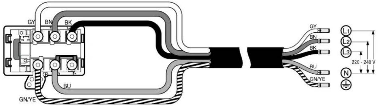
- Disconnect the appliance from the power supply.
- Check whether the connection to the appliance (fig. 4) and the building-side connection (fig. 8) correspond to the connection diagram in these installation instructions.
"Preparing the electrical connection", Page 20
"Establishing the connection to the power supply", Page 23
$$ \rightarrow \text {F i g .} 5 0 $$
$$ \rightarrow F i g. \quad 5 1 $$
$$ \rightarrow \text {F i g .} 5 2 $$
- For 3 N ,observe the following figure.
- For 2N observe the following figure.
- For 1 N, observe the following figure.
Switching the display for air extraction mode
- If required for the air extraction mode and the air recirculation mode, change the display of the electronic control in the basic settings.
- Observe the basic settings section in the instruction manual.
Removing the appliance
ATTENTION!
Tools may damage the appliance frame.
Do not prise out the appliance from above.
- Disconnect the appliance from the power supply.
- Remove the exhaust air duct or undo the circulating-air connections.
- Push out the appliance from below.
fr
Positie van overlooppreservoir:
Fig. 12
ADVARSEL-Fare for forgiving!
ADVARSEL - Brandfare!
Feditaflejringer i fertifiltret kan blive antaendt.
ADVARSEL-Fare for forgiving!
Fastgoring at taeling
$$ \rightarrow \text {F i g .} 3 6 $$
- Fastgor den medfolgende taeling pa fladkanalbogeningen maks. 5 mm fra kanten.
Fastgoring at taeling
Monteringsmal for flat rorbend
Her finner du en oversikt over monteringsmalene for flate rorbend.
Sett fra sider:
Fig. 4, Fig. 5, Fig. 6
Sett forra:
Fig. 7
ADVARSEL-Fare for forgiving!
ADVARSEL-Fare for forgiving!
Montere holdeskinner
Sette inn flatt rorbend
TeH MOrTy 3aBepHyTbCBy UyNaKOBOUHbIMaTePnAIN HnHa-Te b erO ce6e Ha rONoBv N3aDOxHYtbcR.
He noDnyckaTe TeTeK ynaKOBOUHOMy MaTePnany.
He no3BOJIaTe DeTAM INrpaTb C yNaKOBOUHbIM MaTePnaJOM.
I PNEyIPEJXJEHNE -OnacHocTb OtpaBJeHnA!
BTRHYtIe 6bpaTHOBnmeHHe OTPa6oTaBUNe ra3bl MOryT CTaTb PnPHHOOTpABJIeHH.
BbITaKHOI Bo3DyX He DOJKeH BbIXOINbYepe3 DbIMOBYTOpy6y HnN Bo3DyXOBo npn INx 3Knnyataun.
- OTOBDA BbITAKHORO BO3dyxa He CneDyET NcNoIb3oBaTb BEHTKaHaN, Cnykaun DnBeHTnIaun NomeeHIN, B KOTOpbIX yCTaHOBJeHb INCTOuHNKIN PnaMeHn.
PnIOKIOUeHNN BITAKKK K HeNCNOLb3yEMOMy DbIMOxOy, Heo6XoJIMO NOIpyNTb pa3peJeHne B CneuaJIb-HOH INCTaHcHIN, OTBeuAOSe 3a EKnlyaTaunIO N UcTky Tpy6.
BTHyTbe 6bpaTHo B NOMEeHHe OtpaOToBUnHe ra3bl MoryT CTaTb PnPHHO OTPaBJIeHH.
Pn yctaHOBKe BbITAAKKN B NOMEUeHNrX, rde npncytCTByeT nCTOCHNK PIIaMeHN C NOBODOM BO3dyxHa N3 NOMeUeHN, CNCTema NODaCh NITaHNR BbITAAKKN DOJIXHA 6bItbOBOpyIDoBaHa FyHKcneA bApInHOrO OTKJIIOUeHNr.
Yka3aHnno no noKnIOueHHo K 3JIeKTpocetN
IJI630nacHOro NIOKJIQUeHn IpiHbopa K 3NeKTPocETn co6JIOdaIte DaHHbIe HNCTpyKUn.
PNEyPExDEHNE-Onachocb npaHexn 3JIeKTPuueckm TOKOM!
CneJeT o6ecnHb B03MoKHOcTB OTKHoueHINI pInbopaOT 3JIeKTpOcTeN B IIObOIMoMeHT. 3ToT npBOp MOKHO NOKIIuOaTH K cETNI TObKO Upe3 npaBnIbHO yCTaHOBHeHHyOp paCnpedeIeNTbHyU KOPOkY.
B Ctaunohapno 3neKtpoPoBOKe Heo6xOIMo PpeDyCMOTpeb CnuaJIbHb BblKIOUaTeNb DnPa3MbKaHnBCex NIOUCOB cOrnaCHO ycNoBnM KaTeOpn NepeHa npJKeHn III n CoNaCHO yCNOBnM MOtAka.
IoiKluoyehne CtaunohapHoro 3eKtpoo6OpydoBaHHn DOJHKHO pOn3BOoITbCra TOJIbKO KBaIIHmUPOBaHHbIM 3eKtpnKOM.Mbl peKOMeHdyem yCTaHOBHTb yCTpoiCTBO 3aunTHoro OTKluoyehn (Y3O) B 3eKtpuyeckon cenn Chabxhen npu6opOB.
Ipocneinte,HTO6bI cTeBoi Ka6eBHe 6bl 3aKaT,He nepereh6anca HaxoDnCBAaNNOT OCTpbIX KpOMOK.
- PpoklaIbIaIe Te CeTeBOI Ka6eJIb TaK, YTo6bI OH He KaCaIcHarpTeTORO Kopnyca np6opa.
IcnoIb3yIteToIbKOceTeBOKa6eJIb,BXoIaIIINB KOMnIeKTI NOCTaBKn PnIObOpa HIN NoCTaBJIReMbI CepBHCHOH clyk60i.
- 3ToT npH6Op COOTBeTCTByET Tpe6oBaHNm IpaBn EC noNoDaBJIeHHIO paDIOnomEx.
- Pn6op COOTBETCTBYET KJAccy 3aunTb1 I, NOtOMy OH
Должeh 3KcNJIyaTnPoBaTbCRA TOnbKO C 3a3eMnHOUcIM
ПрOBODM.
IpnH3BOJNTeJIb He Hecet OTBETCTBeHHOCTn 3a HeHCnPpAB-HoCTN HIN BO3MOKHe IOBpeXDeHn, KOTOpbie MOryT 6bITb CBA3aHbC HECOOBTcTBYIOuIM 3JeKTPnuueCKM MOHTaXOM.
IodroTOBka K 3JIeKtponoKnIOUoyHnIO
Tpe6oBaHHe:Pa6oTaB C BHTpeHHMn YactrMn np6oopa HIN pOn3BODHT 3aMeHy CeTeBOrO Ka6eMa rTOIbKO npOSeDUnne 06yueHHe cNeuaJInc7b CepBnCHOH cLyK6bl.
- C6bIoudaIte yka3aHnno NO NOKJIIOUeHNIO K 3neKTPocetN. B clyuae HeKOppeKTHoN c6OpKn, HecooTBeTCTByHOuei yctahOBKn IIN NoNOKJIIOUeHN rapaHTNHa npbOp nepe- ctae TNeCTBOBaTb.
2 EcIN Bam Tpe6yetc 60one nnHHb ceTeBOK a6eB, 6paTnTEcb B cepBnCHyIO cnYk6y. B HAnuH NMeOTc Ka6eHN dInHOI do 2,20 M. - Пи установке пиборов бez пеДварпелю сmoHTиpoBaHHoro Ka6eЯ Heo6xOДМо пobecTu cTeBOJ Ka-6eьКpacpeDeIteHOBKopo6ke.
OTKpbBaHne pacnpeJeIeHTelbHO Kopo6Kn
- PpHIOJHMNITe KpbIiKy paCnppeJeIHTeJIbHOJ Kopo6Kn C NOMOuB OTOBepTK.
$$ \rightarrow P u c. \quad 1 5 $$
Iodrotobka pacnpedeJntelbHoi Kopo6Ku
1.Ocna6bTe BnHT.
$$ \rightarrow P u c. 1 6 $$
2ПинлдИМпTe 3aЖIMсnomоьюOTBepTKI.
$$ \rightarrow P u c. 1 7 $$
3.Ocna6bTe 3aHHM.
$$ \rightarrow P u c. \quad 1 8 $$
IopKnIOueHne Ka6eJRA pacnppeJIHTeJb-HoKopo6Ke
$$ \rightarrow P u c. 1 9 $$
1.ПоДКЛHOUHTe KIeMMy 3N Ka6eJI KpacPpeJTeJIbHOI KOPO6Ke, KaK nOKa3aHo Ha cIeDyHOUeM pncyHke.
2 PoiKJIIOUHTe KIeMMy 2 N Ka6eJI K paCppeJTeJIbHoi Kopo6Ke, KaK NOKa3aHO Ha cJeDyHOe M pUCyHKe. Pnc.20
3.ПоДКЛЮЧИТЕКLEММу1Nka6eЯKpacnpeДeNTeHOBI Kopo6Ke, KaK nOKa3aHoHa cNeDyHOUeM pncyHKe. →Pnc.21
4.ПоДКЛIOUHTe KIeMMMy 2L/2N Ka6eЯ KpacpeJeHTeNBHOI Kopo6Ke, KaK nOKa3aHo Ha cNeDyIOUeM pncyHKe. P_NC 22
5. YuHTbBaIte UBeT KaBeJeI.
- BN:kopnUHeBbI
-BU:CNHNI -
GN/YE: JkntbI n 3eHbI
-BK:чepHbI
-GY:cepbii -
Пи Heo6xOAnMoCTn yctaHOBHTe NoCTaBJIReMbIe B KOMJIeKTe MeIbIe IepeMbIyKu COrJaCHO CXeMe NOJ-KJIIOUcHЯ.
7.ПоДКЛIOUHTe Ka6eIa 3aTeM 3aTAHNTe BnHTbHa paCnpedeJIteNtBJHOI Kopo6Ke. - Cornacno cxeme noikkyehn noikkyeHHIO 1 N\~nn2 L/2N cooTBeTcByet pa3a 1 3neKtpoBnraTeIa BeHTnIyTopa.
9.ПОДКИLOЧЕНIO 2N\~/3N\~ COOTBETCTByeT Φa3a L1 (cepbI) 3JIeKTKPODIBRAteTnBEHTINrTopa.
Фнкcaия Ka6eЯВpacnpedeJIHTeJbHoi Kopo6ke
- 3aФнксруне ceteBOJ Ka6eBxOmyTOM.
2.3aTnHTe BHTB npaBnHOM NOIOXKeHN.
-He nCnoNb3yIte aKKymyIaTOpHbI raiKOBePT.
→PUC.23
- TTo6bI yInpOCTnTb 3aKpbIBaHHe paCnPpeJenlTeBHO KoP06Kn, paCNoIOKHTe Ka6eIN B cpeDHe YacTHN Kopo6Kn.
- 3aKpOHTe KpbIuKy Kopo6Kn.
Yka3aHnnoOTbOyBO3dyXa
PpOINBODInTeIb npHbopa He daet rapaHTn B cIyae peKnaMaun, KacaHouxcxryuactkoB Tpy6oPBOda dIy OTBODa BO3dyxa.
Icnonb3yte KOpOTkyo npMyHO BbITaHHyO Tpy6y, MeIOUHO NO BO3MOKHOCTN 0BbJoo DNAmETp.
ДиINHHbIe WepoxOBaTbe BbITaXHbIe Tpy6bl,60nbUoe KOJIInueCTBO KOIEN HIN Tpy6bl MaIOrO dNaMeTppa yMeHbIaIOT MOuHOCtB BbITaXKn IyBeNCHBaIOT wM OT pa6oTbI BEHTINATopa.
Icnonb3yTe BbITXHbIE Tpy6bl N3 HeBocnJaMeHaIOx-Cr MaTePnaIOB.
TTo6bl npedotbpaTntb Bo3Bpat KOHdehcaTa,yCTaHOBnTe BtAHHyTOpy6y nOg yrIOM 1 K npnbopy.
Плockи Каналы
HcnoIb3yIte IIOCKHe KaHaJIbI, BHyTpEHHee CeeyHee KOTOp bIX COOTBeCTByET DnAmEtpy KpyIbIX Tpy6:
DnaMeTp 150 MM COOTBeTCTByeT npM. 177 cm².
Ipn HecooTBeCTBn DnaMaTePoB Tpy6 NcNoJIb3yIte repMeTN3NpyUOuYIOJeHTy.
He nCnoB3yTe nnOckne KaHaIbI c pe3KmMn 3rN6aMn.
KpyrIbIe Tpy6bl
PekomeHdyembI BHyTppeHHn DnaMeTp Kpyrblx Tpy6- 150 MM.
Yka3aHnI pypeKnMa OTbOa BO3dyXa
BpeKHe OToBa BO3yXa DOJIkHa 6bITb yCTaHOBJeHa 3acNoHka 6paTHoN Tn.
PpIMeuaHn
Ecln 3acNoHa o6paTHo Tn He BXoNT B KOMnIeKT noCTaBKn np6opa, eM MoKHO npno6pcTe N CneuaHn3npoBaHHOM MaRa3nHe.
Ecln BbTTKHOB3DyX OTBOINTCAYepe3 HApyHKY0 CTeHy, CNeDyET NcONb3OBAb TeNECKONUeCKN BEHTINJUH OHhI KaHaI, npoxoAunB CTeHe.
PpOBepKa Me6eHn
- Y6eIITecb, yTO Me6eIb IJI BCTpaHbAHy ycTaHOBneHa pOBHo n CnOcO6Ha BbIepKaTb HArpy3Ky. MakcImaJIbHbI BEc np6opa coCTaBnaET npm. 25 Kr. CToJeuHnua, B KOTOpYIO BCTpaHbAetc np6op, DOnJKHb BbIepKHNBaTb HArpy3Ky npm. 60 Kr.
2.ПослЕБынOLнEHЯВblpe3a npOBepbTe yCTOnHBOCTb Me6eINДЯВCTpaHBAHЯ.
3.ObecneBte HecyUHO CnOCo6HOCTb U yCTOuINBOCTb, Oc0eHHO TOHKNX CTOnEWHNU, C NOMOUsHIO NOxODAUXX ONOpHBIX KOHCTpyKuN.
-YunbIaBte BeC np6opa, BKnIOUaA DOONHHTeNHyHO Harpy3Ky.
- IcnoIb3yIte JaponpoHbI N BlaOCToKm MaTePn-an.
-
Y6eIntecb, yTO Me6eIb IINB BCTpaBHaN CnOCo6Ha Bbl- depKHBaTb TempepaTy pO 90 ^ C
5.He BCTpaBaNte DyXOBbIe Wkafo, XOJOnNtBnHKn, NocyDOMoeuHbIe MaunHbI, CTnpaJIbHbIe MaunHbI IN DpyryTOxHNky NO np6opom. -
IpoKoHTpOJIpyTe ToHocTh paCNoJKeHNI npIbopa B rOpN3OHTaJIbHOI NIOCKOCTn NOCNe eRO yCTaHOBKN B MOHTaHHb InpoE M.
YctaHOBKa ONOpHbIX NlaHOK
YcTaHOBtE onOpHbIe PnAHN B Me6eIb.
-Ппкглte onopHbIe nlaHKn K KaMeHHoN CToneWHnIe.
Pp naBoTe C KaMeHHbIMN CToneWHnIaMn NcNoJIb3yTe TepMOCTOKN KNe, NOxODaIIuN dJIЯ cKNeHBaHnI MaTJIa I KaMHa.
-ДЯ npKNeBHaHЯ HeIb3Я IcNoIb3OBaTb CnIKHO-BbI rePMeTnK.
→PUC.24
PoiroTobKa Me6eJH
Tpe6oBaHHe:Me6eBnIaBcTaPbBaHnIdoJIKHa BblepKuBaTb Temnepatpy Do 90 ^ C
- Pa3MeTbTe MeCTo BbIpe3a B Me6eHN B COOTBeTCTBHN CO CXEMO yCTaHOBKN.
→Pnc.14
2.ПрocВерпгteЧeТыpe OTВерсТнЯДиAmeTpOM6MM. →PnC.25
3. YrOJ MeKdIy NOBepxHocTbHO Cpe3a H CToneUHnuei DoJI KHeH CoCTaBnTb 90°
→Pnc.25
Pn yCTaHOBKe HaI BblBHXHbIM AunKOM BblepXHBaIe MHHMaJIbHbIe OTCTyNbl.
1.ПиСНТИЕМКОCTNДЯСЛВАЛIMSHAЕЖИДКOSTHAYCTaHOBJIeHOMпибореcoьногаTe MHHIMaJIbHbIeOTCTybl.
→PUC.11
2. YuHTbIbAte paCNOIOXeHHe EMKoCTn DnR CInBa IINuHHe HNkOcTH.
→PUC.12
IodrotobKa Me6eN K yctaHOBKe npH6opa dIyIuKpyJauHH Bo3dyXa c aIaNTepOM
3aMeTka: YcTaHOBKa Ha BHeUHNe cTeHe 6e3 TeIIOH3OJIaIIN Hn HaN HeOTaJIbAeMbIM NlOM He peKoMeHdyETcR ( ≥ 0,5BT / M^2 C)
1.ПиКOM6HINHPOBAHNc cадANTepoM yHTbIaIte COOTBeTCTBn pa3MePoB BbIpe3a B 3aHHe CTeHKe.
→Puc.26
2.ИЗмерьтToJIинHy cToJIeшинцI.ПepeHecnte 3aМерHa ШабLOн И пОВеДиTe COOTBETCTBYЮУК ПИИНΟ.
→PUC.27
- BbIpeKbTe 7a61oH no pa3MeueHHo IHHn Ia TOnuHbI CToneuHnucB A, cHTpaIbHOJ IHHN Bbipe3a B n KOHTpOJIbHOJ IHHN IaI BHyTpEHHero BblNyCKHOrO OTBepCTnA C.
- OTMeTbTe ueHTp Bbipe3a B CToneuHnue ueHTpaJIbHOJ HnHe Ha 3aDHeI CTeHKe Me6eII.
→PUC.28
- BbipOBHnTe WApIOH No CEHTpaIbHOJ IINHH Ha 3aHHe CTeHKe Me6eN N IO HxKHeMy KpaO CToneUHNuBJI.
- CdelaIaIe BbIpe3 B 3aIHei cTeHKe B COOTBeTCTBnC Ila- 6JIOHOM.
7.ПослЕ ВынOLнEHиВ Bipe3a yДаЛпTe OПИКИ. - 3aRepeMeTn3npyIe CTbIKN TePMoCTOKNM IN BOHOHePNOHnIaEMbIM RepeMeTNIKOM.
→Pnc.25
BeHTnlaucna
1.YCTaHOBtBe BO3dyuHbI KJIanaH B zuKone dIpyeXnMa CnpKyJUcIN BO3dyxa.
-MHHMaJIbHoe nonepeHoe ceyHne BO3dUshHO KnaHa HOnJHo 6bTb npM. 400~cm^2
-BbInyckHoe OTBepCTne B OOKOJIe DOJIKHO 6blTOCTaTouHObIbIM, YTObI ObecneuHTb TAY Hn3Kn ypoBeHb Wyma.
- TTo6bI npn6op fynKUHOHPOBaI npaBnIbHo, o6ecneYbTe npITOK Bo3dyxa K BapOuHoi NaHei Ype3 OTBepCThe DnB BixOda Bo3dyxa C MINHMaJIbHbIM NOpEpeHbIM CeueHem 200cM² B HxKHeM WkaFy.
YcTaHOBKa np6opacpeKHMOM cnKpyLauu BO3dyxa c aanTePOM Kpenenne ynloTHHTeHa aanTepe
3aKpeHnTe yIIOTHnTeIb Ha aIaIaTepe Ha pacCToHn Hc 60nee 5 MM OT Kpa.
→Puc.29
YctaHOBKa aanTepa
- OuHCTHe N o6e3KnPbTe NOBepxHocTb PnPKJIeNBaHH BOKpyr BbIpe3a B 3aDHei CTehKe Me6eHN.
2.YcTaHOBnTe aAnTep B BbInyckHoe OTBepCTne B 3aHeN YaCTn BapOHyI NaHEII.
→PUC.30 - CHIMITE 3aunTHyU nHc KaanTepa.
PUC.31
YctaHOBka np6opa B BBipe3 CTOJeHHue
- Y6eIntecb, qTo cTeBoi KaebIb noKnIOUeyH K npHbOpy.
2.AkkypaTHO ycTaHOBNTe np6Op B BBpe3 cToJIeUHnUbl. P_NC 32
Фнкациаадпетера
- YdepeKnBa CpeHn DepeKaTeB aAaTepa, CdBnHbTe ero 6OKOBIMn DepeKaTeJMaN K 3aDHe NCTeHKe B HnKHeM shkaFy n npNKneIte. P_NC 33
2.Пи Heo6xOIMOCn DoONHHTeNbHO 3aФHKcpyIte aIanTep BNHTaMn. P_sc 34
IoproBka Me6eN K yctaHOBKe np6opa IJIa CHPKylraun BO3dyxa C cHPKylraunoHbIM KaHaJOM
1.Пи Heo6xOaHMoCtN CHIMITE 3aHIOU CTeHKy Me6eHN.
2.ПиКOM6HINHPOBaHN CПLOCKIM KaHaIOM yuHTbIBaHTe COOTBETCTBHe pa3MepOB Bblpe3a B 3aDHei CTHeKHe. P_NC [35]
3.YcTaHOBnTe Bo3DyUHbI KlaHaH B zuKoNe IaIpeKIma CnpKyJrCmN BO3DyXa.
-MHmMaIbHoe nOpeuHoe ceeHne BO3duHoro klaHa D0JXHO 6bTb npM.400 cm².
-BbInyckHoe OTBepCTne B OOKone DoJHKHO 6bITb DOCTaTOUHO 60JIbWIM, YTO6bl ObecneuHTb TAY Hn3Kn ypoBeNb Wyma.
- TTo6bI npn60p fynKUHOHPOBAn npaBnIbHo, oBeCneBTe npTOK Bo3dyxa K BapOuHoi naHei Ype3 OTBepCTne DnA BixOda Bo3dyxa C MINHMajlbHbIM NOpEpuHbIM ceHem 200cM² B HnKHeM uKaФy.
- Nocne BbInonHeHHBbpe3a ydaJIte ONnKn.
- 3aRepeMeTHn3HpyTe CTbIKN TepMOCTOnKIM N BOHOHeIPO-HuCaembIM TepMeTNIKOM. Pnc.25
YcTaHOBKa npH6opa IaI pa6Otbl B peKHMe UINPKyJIaIcHn BO3dUxac INPKyJIaIcHNOHHbIM KaHaJlOM
- IcnoIb3yIte yIInoTHIeIb, cIpyKyIaIIOHHb KaHaI, dIΦ-Фу3Op IФИbTp dIyIaIeHnI 3anaxOB BpeKImpeIcnpKyJIaIu BO3dYxa.
- YHTbBaIte pa3Mepb pa3JIuHbIX IIOCKHX BO3dYXOBoB. CtpaHua 73
ФнкацулnotHTteJIa
3aKpeNITE BXOJUINB KOMNJIeKT NOCTaBKN yNIOHTeJIb Ha NIOCKOM KaHane He daJIbIe 5 MM OT KpaI. P_NC 36
YctaHOBka NIOCKORKaHaJa
YcTaHOBnTe PNOCKn KaHaI B BbInyCKHoe OTBepCTne Ha 3aJHei CTeHKe npNo6opa. Pnc.37
YctaHOBka np6opa B Bbipe3 B CToJeHHue
- Y6eIntecb, yTo cTeBoi KaebIb noKIIoucen K npHbOpy.
2 AKKypaTHO yCTAHOBNTe np6op B BBpe3 cToJeHHuBl. P_NC 38
YcTaHOBbCa ChCTeMbI Tpy6 MeHdI npH6Opom HnΦΦy3OpOM
- CoeHHHe KOMHOENTbI cHpKyJIaIOHOHorO KaHaJa MeJx dy co6oJ.
-3aKpeHnTe CoeHHnTeHn PnOckHX BO3dYxOBOOB, 3a-ΦHKcHPOBaB HX CO UeJIyKOM.
-ДЯболгунгдэйногиФИКСАИпprИКpyTITe coEDINHITIELПLOCKORBO3dYxOBOJa4BHTAMMДЯПlaCTNKAPT 4x8MM.→Pnc.39
2IooeHnHTeUINPKyJauHHbKaHaC nPiocKm BO3- DxyoBOOM K 3aJHe YacTn BapOuHOI NaHeII. P_sc 40
3.ПодсоeДинITEДИФФузOPKцИРКУЛЯЦИОнHOMyKaHany. →Pnc.41
IodrotOBKa Me6eJn IJIy yCTaHOBKn peKIMa OTbOda BO3dyxa
1.Пи Heo6xOДMOCtN CHIMITE 3aHIOCTeHKy Me6eIi.
2ПиКOM6HINPOBAHIN CПLOCKIM KaHaJOM yuNTbIaJIte COOTBeTCTBNE pa3MePoB Bblpe3a B 3aJHe cTeHKe. P_NC 42
- Nocle BbInoJIHeHnB Bipe3a ydaJIte OINIKN.
4.3aRepeMeTHn3HpyTe CTbIKN TepMOCTOKNIM N BOHOHePOnHnIaEMbIM TepMeTNIKOM. P_NC 25
YcTaHOBka npH6opa IJIpa6OtBI B peKHe MTBOJa BO3dYxa
- B pexime OTbOa Bo3dyxa HcNoIb3yIe yIIOTHnTeIb IyMOnOrloaIoUneФIbTpbl.
- Co6nOdaIte yka3aHn no paBote B peKHe M e OTbOa BO3- dyxa. CtpaHua 75
ФнкацуYPNLOTHHTeJIa
3aKpeNTe BXOJaIINB KOMnEKT NocTaBKN yNIOHTeJIb Ha IIOCKOM KaHaJIe He DaJIbWe 5 MM OT KpaJ. P_NC 36
YctaHOBKa CnCTembl Tpy6
- YctaHOBInTe PINOckn KaHaJI B BbInyCKHoe OTBepCTHe Ha 3aJHei CTeHKe npNo6opa. PUC.37
2Ipn Heo6xOAnMoCTn MOHTnpyTe DOnoHHTeNbHe 3neMeHTbI CNTeMbI Tpy6.
YcTaHOBka np6opa B BBipe3 CTOJeHHue
- Y6eIntecb, yTO cTeBoi KaebIb NpIKJIouChEN K npIbOpy.
2.AkkypaTHO yCTAHOBITE npH6Op B BBIpe3 cToJIeUHHUJI. P_NC 38
IopcoeHHeHne BbITaHHoTpy6bl
- 3aKpeIe BbITJHHyIO Tpy6y Ha KOJIeHe IIOCKORO BO3dYXOBoJa.
2 BbINOJIHHTe COeINHeHHe C BbITaXHHbIM OTBepCTHeM. - 3aRepeMTeHn3pyIte MeCTa CoeINHeHHa COOTBeTCTByIOUIM O6pa3OM.
YctaHOBkaΦHbTpOB
3aMeTHa: B peKHMe cIrpKyIaIu ycTaHOBHTe FInbTpbl, nOrloaIOUne 3anax.
BpeKnme OToBa BO3dyxya yCTaHOBITE WymONOrNoaHouneΦnIbTpbl.
- 06paTHe BnMaHne Ha HnPaBHeHne Bo3DyUHOro NtOKa ΦnIbTpOB.
2.BctaBbTe B npn6op Dba fNtpa CneBa n cnpaba N CdBnHbTe IN Bnpeq.
→PNC.43
- BCTaBbTe B npn6op npyrgne DBA pntbtpbl cneBa n cnpaBa.
→PnC.44
YcTaHObKa HnpoyNaBnHbAIOUeO HJIbTp a
YcTaHOBnTe KInpoynabNBAIOUmHnIbTp.
→PUC.45
3neKtpnuecKoe noDKIIOUeHne
- YuHTbBaIe npaMeTpbl NOdkluoyehnHa TInoBOI Ta-6JnUKe.
2.ПодключITEКлему3Nka6eЯнрacnpedentelhoKopo6ke,KaNKoKa3aHoHa pncyHke.
PnC.46
3.ПоДКЛIOЧИТЕКЛEMМУ2Nka6eЯнpacпpeДENITeHOBIN Kopo6ke,KAKnOKa3aHOHaPcCyHKe.
→Puc.47
4.ПодклioчiteКлемmy1Nka6eЯKpacpepeHteьног Kopo6ke,KaKpoKa3aHoHa pncyHke.
→Pnc.48
5.Подклочп Клемmy2L/2NКабеляKpacnpedentel-нов Коробke,Кak noka3aHoHa pncyHke.
P_HC 49
6. YuHTbIaBte ZbET KaBeNei.
-BN:KOpuHneBbI
-BU:cHHN
- GN/YE: JkntbI n 3eHbI
-BK: Yephbl
-GY:cepbii
- B 3aBnCmOCTn OT Tnna NpDkJIuOeHn, npi Heo6xOaMocTn paCnONIOKHTe Ka6eNbHbIe 3aXHMbl, NOcTaBnEMBIe B KOMPNeKTe, No-pa3HOMy.
-
Pn Heo6xOaHMOCTN Hcnonb3yIte Ka6eIbHbIe 3aKIMbl Dnra coeDInHeHH DaByX Ka6eIe.
-
YKOPOTNE KINbI Ka6eJIeN.
-YdannTeH3OJIaIIO.
PpOBepka pa6oTbI
- BkHouHTe npH6op.
2.Ecnn 3aropaeTcN O400, E8513 npnOp noKnHOn-ueH HeKoppeKTHO.
"PpOBeRka n OToJaKa IOnKnHoueHnK 3NeKtpocetN", CtpaHnua 77
- EcIn Ha DnCnnee np6opae He noBnEeTcHnDnKaun OuN6ok, npOBepbTe pa60Ty BeHTnJIaun, cNeDuY pyKOBOCTBy NO 3KcNpyaTuIN.
PpOBepKa H OTlaIka NODKJIIOUeHnK 3JneK- TpOcETn
- OToeDHHTe npH6Op OT cETN.
2.Y6eIntecb,yTO NOKJIIOUeHHe Ha npBope (pnc.4) nNoI KJIIOUeHHe Ha CTeHe (pnc.8) COOTBeTCTByIOT CXEme NODKJIIOUeHnB INHCTpyKuINN IO MOHTaKy.
"IoiIOrOToBk K 3JIeKtPOnIOKnIIOHueHnIO", CtrpaHnca 74
"3neKtpnueckoe noKnIOueHHe", CtpaHua 77
3.ДЯ3N O6paTne BHNMaHHe Ha cNeIyUOuIn pncyHOK. →Pnc.50
4.ДЯ2NobpaTneBHIMaHHeHaCneIyOuynpucyHOK. →Pc.51
5.ДЯ1N O6paTne BHMaHHe Ha cIeIyOuIIN PnCyHOK. →PnC. 52
IpepeHaCTpoiKa HnHnKaaun Ha peXHM OTBOda BO3dyxa
- Пи НeoбхоДИМОСТ ИпЕнэсТРОЛТЕ COOTВETCTBYIOUIM M OБразOM 3ЛЕКТПОНhoe ynpaBNeHne B 6a3OBbIX yCTaHOK Kax ДЯ ржима OTBOda BO3dYxa.
- CM. rnaBy «Ba30BbIe yCTaHOBKn» B pyKOBoIDCTBe no 3Kc- nlyataun.
Демонтан пибopa
BHIMAHNE!
Pn HcNoB3OBAHn HNCTpyMeHTOB MoKHO NOBpeDntb paMy np6opa.
He n3BneKaai Te npH6op CBepxy.
- OToeDHHte npH6Op OTNeKTPocEtN.
- CHIMTE BbITXHON KaHaN INOcIa6Be coeINHeHne INR cIPKyJIaUN BO3Dyxa.
3.ИЗБLEКТЕпнбов,БВITOKHNYB eRo cHn3y.
- es
- QR code for the installation video
- Appliance dimensions
- Installation dimensions for flat duct bends
- Installation variants
- Odour filter and adapter for circulating-air mode:
- Acoustics filter and seal for air extraction mode: → Fig. 10
- Safety clearances
- General information
- Safe installation
- WARNING - Danger: Magnetism!
- WARNING - Risk of poisoning!
- WARNING - Risk of fire!
- WARNING - Risk of injury!
- WARNING - Risk of suffocation!
- Information about the electrical connection
- WARNING - Risk of electric shock!
- Preparing the electrical connection
- Opening the mains socket
- Preparing the mains socket
- Connecting the cable to the mains socket
- Secure the cable in the mains socket
- Instructions for the exhaust air pipe
- Flat ducts
- Round pipes
- Instructions for the air extraction mode
- Notes
- Checking the units
- Installing the support rails
- Preparing the units
- Observing the minimum clearances when installing above a drawer
- Preparing the unit for circulating-air mode with the adapter
- Ventilation
- Installing an appliance featuring circulating-air mode with adapter
- Attaching the seal to the adapter
- Attaching the adapter
- Inserting the appliance into the worktop cut-out
- Securing the adapter
- Preparing the unit for circulating-air mode with a circulating-air duct
- Installing the appliance for air recirculation mode with circulating-air duct
- Securing the seal
- Inserting the flat duct elbow
- Establishing the pipework between the appliance and the diffuser
- Preparing the unit for air extraction mode
- Install the appliance for air extraction mode
- Establishing the piping
- Connecting the exhaust air pipe
- Inserting filters
- Inserting grease filters
- Establishing the connection to the power supply
- Checking the function
- Checking and correcting the electrical connection
- Switching the display for air extraction mode
- Removing the appliance
- ATTENTION!
- fr
- ADVARSEL-Fare for forgiving!
- ADVARSEL - Brandfare!
- Fastgoring at taeling
- Monteringsmal for flat rorbend
- Montere holdeskinner
- Sette inn flatt rorbend
- I PNEyIPEJXJEHNE -OnacHocTb OtpaBJeHnA!
- Yka3aHnno no noKnIOueHHo K 3JIeKTpocetN
- PNEyPExDEHNE-Onachocb npaHexn 3JIeKTPuueckm TOKOM!
- IodroTOBka K 3JIeKtponoKnIOUoyHnIO
- OTKpbBaHne pacnpeJeIeHTelbHO Kopo6Kn
- Iodrotobka pacnpedeJntelbHoi Kopo6Ku
- IopKnIOueHne Ka6eJRA pacnppeJIHTeJb-HoKopo6Ke
- Фнкcaия Ka6eЯВpacnpedeJIHTeJbHoi Kopo6ke
- Yka3aHnnoOTbOyBO3dyXa
- Плockи Каналы
- KpyrIbIe Tpy6bl
- Yka3aHnI pypeKnMa OTbOa BO3dyXa
- PpIMeuaHn
- PpOBepKa Me6eHn
- YctaHOBKa ONOpHbIX NlaHOK
- PoiroTobKa Me6eJH
- Pn yCTaHOBKe HaI BblBHXHbIM AunKOM BblepXHBaIe MHHMaJIbHbIe OTCTyNbl.
- IodrotobKa Me6eN K yctaHOBKe npH6opa dIyIuKpyJauHH Bo3dyXa c aIaNTepOM
- BeHTnlaucna
- YcTaHOBKa np6opacpeKHMOM cnKpyLauu BO3dyxa c aanTePOM Kpenenne ynloTHHTeHa aanTepe
- YctaHOBKa aanTepa
- YctaHOBka np6opa B BBipe3 CTOJeHHue
- Фнкациаадпетера
- IoproBka Me6eN K yctaHOBKe np6opa IJIa CHPKylraun BO3dyxa C cHPKylraunoHbIM KaHaJOM
- YcTaHOBKa npH6opa IaI pa6Otbl B peKHMe UINPKyJIaIcHn BO3dUxac INPKyJIaIcHNOHHbIM KaHaJlOM
- ФнкацулnotHTteJIa
- YctaHOBka NIOCKORKaHaJa
- YctaHOBka np6opa B Bbipe3 B CToJeHHue
- YcTaHOBbCa ChCTeMbI Tpy6 MeHdI npH6Opom HnΦΦy3OpOM
- IodrotOBKa Me6eJn IJIy yCTaHOBKn peKIMa OTbOda BO3dyxa
- YcTaHOBka npH6opa IJIpa6OtBI B peKHe MTBOJa BO3dYxa
- ФнкацуYPNLOTHHTeJIa
- YctaHOBKa CnCTembl Tpy6
- IopcoeHHeHne BbITaHHoTpy6bl
- YctaHOBkaΦHbTpOB
- YcTaHObKa HnpoyNaBnHbAIOUeO HJIbTp a
- 3neKtpnuecKoe noDKIIOUeHne
- PpOBepka pa6oTbI
- PpOBepKa H OTlaIka NODKJIIOUeHnK 3JneK- TpOcETn
- IpepeHaCTpoiKa HnHnKaaun Ha peXHM OTBOda BO3dyxa
- Демонтан пибopa
- BHIMAHNE!
Brand : SIEMENS
Model : EH875BE15E
Category : Cooker