
CRD8160B - DVD player LG - Free user manual and instructions
Find the device manual for free CRD8160B LG in PDF.

User questions about CRD8160B LG
0 question about this device. Answer the ones you know or ask your own.
Ask a new question about this device
Download the instructions for your DVD player in PDF format for free! Find your manual CRD8160B - LG and take your electronic device back in hand. On this page are published all the documents necessary for the use of your device. CRD8160B by LG.
USER MANUAL CRD8160B LG
To enjoy fully all the features and functions of your CD-ROM Drive, Please read this Owner's Manual carefully and completely.

LG Electronics Inc.
CAUTION: The laser used in the CD-ROM drive can damage your eyes.
Do not attempt to open the cover.
To reduce the risk of electric shock, do not remove cover (or back).
No user-serviceable parts inside.
Refer servicing to qualified service personnel.
This unit uses CD-ROM discs
marked with this symbol:

Use of controls or performance of procedures other than those specified herein may result in hazardous radiation exposure.

PRODUCT COMPLIES WITH DHHS
RULES 21 C.F.R. SUB-CHAPTER J.
IN EFFECT AT THE DATE OF MANUFACTURE.
WARNING: To reduce the risk of fire or electric shock,
do not expose this appliance to rain or moisture.
CSA Notice
This class B digital apparatus meets all requirements of the Canadian Interference-Caising Equipment Regulations.
Note : This equipment has been tested and found to comply with the limits for a Class B digital device, pursuant to Part 15 of the FCC Rules.
These limits are designed to provide reasonable protection against harmful interference in a residential installation. This equipment generates, uses, and can radiate radio frequency energy and, if not installed and used in accordance with the instructions, may cause harmful interference to radio communications.
However, there is no guarantee that interference will not occur in a particular installation. If this equipment does cause harmful interference to radio or television reception, which can be determined by turning the equipment off and on, the user is encouraged to try to correct the interference by one or more of the following measures:
- Reorient or relocate the receiving antenna.
- Increase the separation between the equipment and receiver.
- Connect the equipment into an outlet on a circuit different from that to which the receiver is connected.
- Consult the dealer or an Authorized Service Center for help.
FCCWARNING
Changes or modifications not expressly approved by the party responsible for compliance could void the user's authority to operate the equipment.
- FCC This CD-ROM Drive is for use only with UL listed personal computers that have installation instructions detailing user installation of card cage accessory.
Your new 16X CD-ROM drive utilizes a combination of Constant Angular Velocity (CAV) and Constant Linear Velocity (CLV) disc rotation to achieve the ultimate performance. Previously, CD-ROM drives utilized only CLV technology to rotate the disc which resulted in a constant data transfer rate by adjusting the CD-ROM's rotation. In other words, the drive's motor would slow down to read data located on the outer tracks.
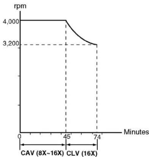
However, as transfer rates increased beyond 1.2 Mb/sec (8X), the motor rotation became so fast that it caused too much vibration and noise. With a combination of CAV and CLV technology, LG Electronics is able to achieve a maximum transfer rate of 2.4 Mb/sec (16X), speed up the access time to 100ms. At the same time, CAV+ CLV technology causes considerably less noise and vibration than high speed CLV only CD-ROM drives.
FEATURES
E-IDE interface
100ms average access time
Multimedia PC compatible
Photo CD multisession support
Small CPU bandwidth (MPC spec.)
16X-speed Max 2400KB/sec data transfer rate
Intelligent 128KB data buffering system
Horizontal/Vertical mounting support
Tray Loading system without caddy
Designed for internal mounting
Emergency Eject Support
Easy audio CD control button support
Supports Windows 95 Plug and Play ATAPI protocol
SYSTEM REQUIREMENTS
An IBM PC or compatible with the following system components:
IBM Compatible 486SX or above
A Minimum of 640K memory
Floppy disk drive (312 inch)
MS-DOS version 3.1 or greater
An open, front-facing, half-height drive bay.
■ An existing IDE controller in your PC with an available cable connector or a new IDE controller that you will install.
SUPPLIED ACCESSORIES
| Item | Quantity |
| Owner's Manual | 1 |
| Setup diskette | 1 |
| Audio Cable | 1 |
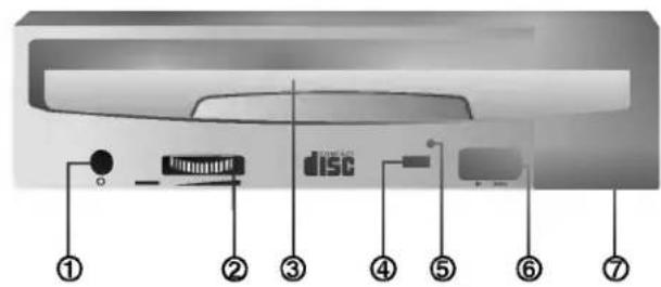
Figure 1. Front View
FRONT VIEW
1. Headphone Jack
3.5mm jack for monitoring the audio signal from audio CDs.
2. Headphone Volume Control
Adjusts the headphone sound level.
3. DiscDrawer
Accepts a CD-ROM disc on its tray.
4. Busy Indicator
The Busy Indicator lights during initialization and data-read operations.
5. Emergency Eject Hole
Insert a paper clip here to eject the drawer manually or when there is no power.
6. Play/Skip Button
When an Audio CD is in the Disc Printer, pressing this button will start playing audio CDs from the first track. If an audio CD is playing, pressing this button will skip to the next track./
7. Open/Close/Stop Button
This button is pressed to open or close the CD tray.
The button works only when power is applied to the drive.
If an audio CD is playing, pressing this button will stop it, and pressing it again will open the tray.

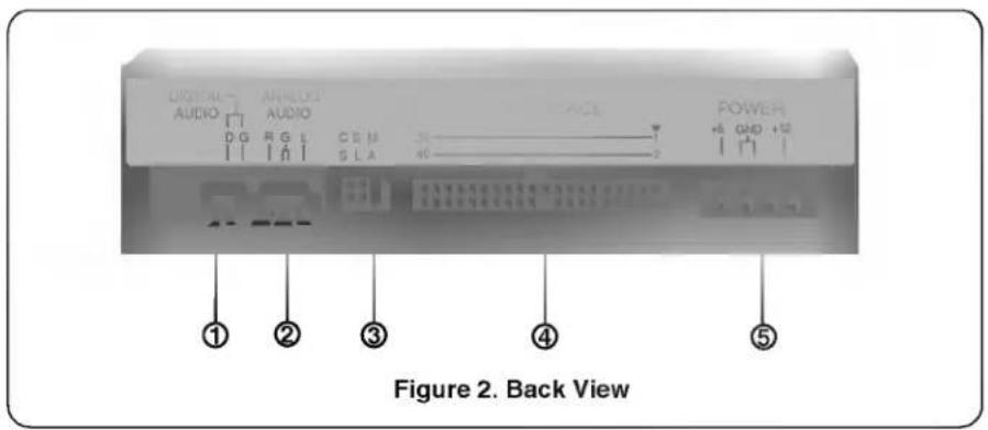
BACK VIEW
1. Digital Audio Output Connector
This is a digital audio output connector or Video CD output connector.
You can connect this to the digital audio system or Video CD Board.
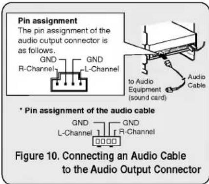
2. Analog Audio Output Connector
The Audio Output Connector connects to a sound card
The supplied audio cable is a SoundBlaster type cable. If you have a different sound card, you will need to contact the sound card manufacturer to obtain the proper cable for that card.
3. Master / Slave / CSEL Jumper
These three jumpers are used to set the CD-ROM Drive to either a Master, Slave, or CSEL drive.
Refer to section HARDWARE INSTALLATION.
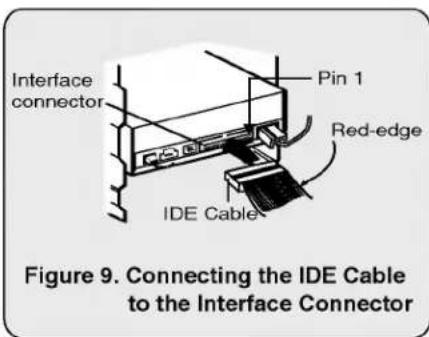
4. Interface Connector
This 40-pin connector is used to transfer and control signals between the CD-ROM Drive and your PC.
Connect the 40-pin IDE cable in your PC to this connector.
5. Power-in Connector
Attach a power cable from the computer to this connector.


Installation
Avoid placing the drive in a location subject to :
- high humidity
- high temperature
-mechanical vibration - direct sunlight
Operation
- During operation, excessive vibration or a sudden jolt to the drive may cause a malfunction.
- Avoid exposing the drive to sudden changes in temperature. This may cause condensation to collect inside the drive.
Transportation
- Always remove the disc before moving the drive.
This section describes how to install your CD-ROM drive into your computer.
WARNING:
To protect the CD-ROM Drive, your computer, and peripheral devices from damage, turn off their power before installing the drive.
Note: If you are not comfortable about opening your PC and attempting the CD-ROM drive installation, many local computer shops can perform this service for a reasonable cost.
This installation assumes you have a PC with an available connector on an IDE interface cable. If your PC has an IDE hard drive, there is usually an available connector in the middle of the same cable that attaches from the motherboard (or controller card) IDE connector to the hard drive. If the last sentence does not describe your system, you may need to purchase an IDE controller card to install this CD-ROM drive. Inspecting and knowing your PC system will make your installation easier and less time consuming.
A final note before installation: The cable connecting to your floppy disk drive is not an IDE cable. Do not attempt to attach the CD-ROM drive to this cable.
If the CD-ROM drive is to be connected to the same cable as the hard drive, be sure that the hard drive is set as master. Hard drives can be set as single, master, or slave. Check your hard drive owner's manual or contact the hard drive manufacturer for correct jumper settings.
- You will see three pairs of pins and a jumper (cap) at the back of the CD-ROM drive. This jumper is used to set the CD-ROM Drive as a CSEL, MASTER, or SLAVE device in your PC. Examples of how the jumper can be placed are shown in Figure 3 below.
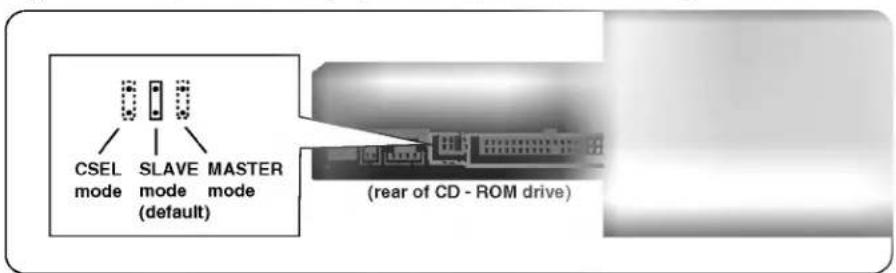
- Move the jumper (clip on one pair of pins) from its default factory position (SLAVE), to CSEL or MASTER as needed (see the following description for the setup that matches your system), using the above diagram to place the jumper.
WHEN USING A PRIMARY IDE CONTROLLER
Most PCs provide one IDE cable to support two devices (one for hard disk, the other for a second hard disk or a CD-ROM drive). This IDE cable originates either on the motherboard or on a controller card. This controller is termed the primary IDE controller, and the hard disk attached that contains the operating system for boot-up is set up as the Primary Master. Your CD-ROM drive should be set to the Slave mode.
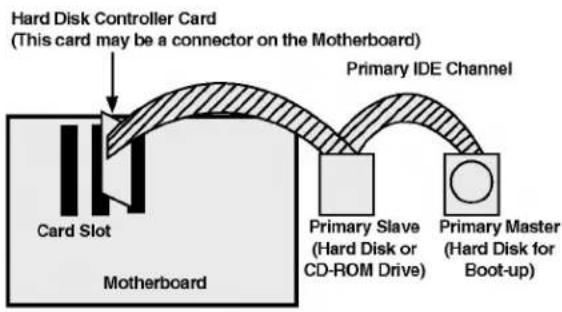
Figure 4. Primary Controller system Configuration
Note:
Many older 1X and 2X CD-ROM drives used a 40 pin controller card that were not IDE compatible. These were proprietary interface cards for use with a particular model CD-ROM Drive. Many older Sony, Panasonic, and Misumi drives used 40 pin proprietary interface cards. If you are upgrading from an older CD-ROM drive, your new CD-ROM will not work on a proprietary interface card. You will need to buy a secondary IDE controller card.
WHEN USING A SECONDARY CONTROLLER
- If your PC has an additional IDE controller on the motherboard or on a system slot, each IDE device connected to the secondary IDE controller must also be set to the Master or Slave mode. If you are connecting your CD-ROM drive to a secondary IDE card, and it is the 1st device you are connecting to it, then set the CD-ROM jumper to the Master position. If it is the 2nd device, set the CD-ROM jumper to the Slave position.
- Depending on the IDE card and whether the CD-ROM drive is a master or slave unit, the diagram below represents the different ways in which the CD-ROM may be configured in your PC. The table below the diagram shows the possible Jumper placements that would correspond to each of the different configurations shown.
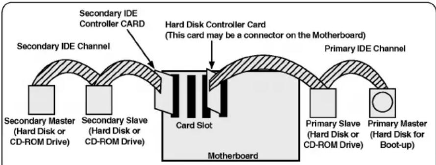
Figure 5. Possible System Configuration

| IDE Controller | CD-ROM Connection | Jumper Placement |
| Primary (1st IDE card) | Slave(Hard disk is Master) | SLAVE (default) |
| Secondary (2nd IDE card) | Master(1st device on 2nd IDE Card) | MASTER |
| Secondary (2nd IDE card) | Slave(2nd device on 2nd IDE Card) | SLAVE (default) |
| PC Manual says use CSEL | CSEL |
MOUNTING THE CD-ROM DRIVE
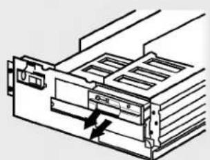
Figure 6. Removing the Floppy Disk Drive and the Blanking plate
Step 1. Turn off and unplug your computer and all peripheral devices attached to it.
Step 2. Remove the cover from your computer.
Step 3. Remove the front panel from an unused half-height slot.
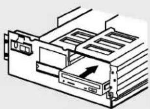
Figure 7. Mounting the Drive
Step 4. Slide the CD-ROM drive into the half-height slot, and secure the drive in place with screws and brackets.
Note: If there is too much space between the sides of the drive and the drive bay, you may need to install spacer brackets, available at your local computer store.
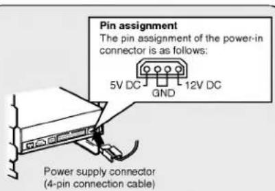
Figure 8. Connecting the Power Supply Cable
Step 5. Push the power supply cable connector firmly into the power in connector.
CONNECTING AN AUDIO CABLE
Step 6. Connect the 40-pin IDE Cable to the back of the CD-ROM Drive. Please make sure that the red edge of the IDE Cable is connected to Pin 1 on the CD-ROM Drive.
If you want to connect audio equipment or a sound card to the CD-ROM drive, use an audio cable to connect the drive to the sound device.
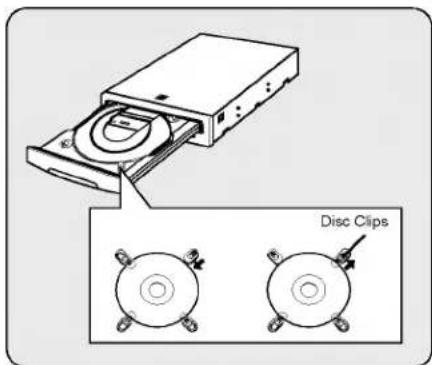
Note: This CD-ROM Drive can be used vertically.
To use the drive vertically, open the drawer and move the 2 plastic clips on the bottom to hold a disc vertically. After placing a CD into the tray, move the top 2 plastic clips to hold the top of the CD in place. Use only standard 12cm discs.
- Do not touch the unlabeled side of the disc.
THE SET UP PROCESS
The INSTALL program performs the following functions.
- Allows the user to select the target disk drive where CD-ROM device driver files will be set-up.
- Unless modified by the user, the INSTALL program searches the target disk for directory(\CDROM); if it is not found, the directory(\CDROM) is created.
- Copies the CD-ROM device driver file named GSCDROM.SYS, the Microsoft CD-ROM Extension file named MSCDEX.EXE, and the utility files to the specified directory.
- Modifies your CONFIG.SYS file to list the location and name of the device driver.
- Modifies your AUTOEXEC.BAT file to load MSCDEX.
Terminates and returns control to the user.
LIST OF FILES TO BE INSTALLED IN YOUR PC
- MSCDEX.EXE Microsoft MS-DOS CD-ROM Extension software, which enables the computer to access the CD-ROM drive.
- GSCDROM.SYS CD-ROM device driver.
- EJECT.EXE Software eject program which can eject the CD tray.
*CLOSE.EXE Software close program which can close the CD tray. - LOCK.EXE Program which disables the Eject Button. The Eject Button will not function in the locked state. The lock function is useful when you are using the CD-ROM drive for important work.
- UNLOCK.EXE Program which enables Eject Button.
Eject Button will function properly after executing the unlock program.
RUNNING THE INSTALL PROGRAM (DOS INSTALLATION)
Step 1. Insert the CD-ROM device driver install diskette into the appropriate drive.
Step 2. Go to the floppy drive by typing A: or B: at the DOS prompt, as appropriate.
Step 3. Type the word INSTALL and press [ENTER].
Step 4. The INSTALL program will begin loading. When loading is complete, the INSTALL program identification will appear on the screen.
Step.5. Follow the instructions on the screen.
Step 6. If you specify the path information during the installation, the install program will copy the CD-ROM device driver file named GSCDROM.SYS, the Microsoft CD-ROM Extension file named MSCDEX.EXE and the utility files to the specified directory, and modify your CONFIG.SYS file and AUTOEXEC.BAT file.
Step 7. When the installation is completed, remove the diskette, and reboot your PC.
CD-ROM EXTENSION PROGRAM MSCDEX.EXE OPTIONS
There are several options that are set for the Microsoft CD Extension program. Generally, these settings do not have to be changed for the CD-ROM drive to work, so these options are needed no further. However, you may decide to change the MSCDEX option settings depending on your operating environment.
These options are explained below:
| PARAMETER | DESCRIPTION |
| /D (Device Name) | Tells MSCDEX.EXE what the device driver's name is (must be same as was used in "/D:" expression of "DEVICE=" line in CONFIG.SYS file) |
| /E | Tells MSCDEX.EXE to use expanded memory |
| /L: (Device Name) | Indicates the drive letter to be assigned to the CD-ROM drive |
| /M: (Value) | Tells MSCDEX.EXE how much memory to allocated for caching. Default is 10 (represents 10 kilobytes). |
| /V | Provides memory usage statistics, such as how much memory is used by buffers, resident data, and resident code. |
ATAPI Installation (Windows 95 and others)
- For Windows 95 installation, do not use the installation diskette supplied. This CD-ROM drive is Windows 95, Windows NT 3.5, and OS/2 Warp compatible, generally utilizing the generic software drivers supplied with those operating systems Below is the example installing the driver for Windows 95. For other operating systems, try looking for either a LG Electronics or Goldstar IDE CD-ROM drive software driver. If none is found, try selecting one of the device drivers for Non-listed IDE CD-ROM.
(For Windows 95)
- Install the CD-ROM drive in your PC as described in this manual.
- Power up your PC. Upon starting Windows 95, it might automatically detect the new CD-ROM drive and load the driver software for it. If not, proceed to the next step.
- In Windows 95, Click on the Start button. Click on the Settings button. Click on the Control Panel button. Double-Click on the Add New Hardware icon. Follow the instructions for the computer to search your system for new hardware. It will locate the CD-ROM drive and load the generic driver.
TROUBLESHOOTING
- When the CD-ROM drive does not work with the hard disk drive in primary IDE channel.
(SOLUTION)
- Check the CD-ROM drive Master/Slave Jumper setting. The CD-ROM drive must be set to the Slave mode.
- Check to be sure your hard disk Interface type is IDE type.
- Check your hard disk Master/Slave Jumper setting. Some old-version IDE type hard disks were set to Master Only mode. In that case, contact your hard disk company and change your hard disk jumper setting to master mode.
- If the CD-ROM drive does not work with above methods, you may need a secondary IDE card. If you use the secondary IDE card, you should set the CD-ROM drive jumper to the master mode if the CD-ROM drive is the first device you are connecting to the secondary IDE card.
- When the CD-ROM drive does not install in OS/2 warp.
(SOLUTION)
- Select NON-LISTED IDE CD.
- CD-ROM drive is not present in Windows 3.1 or 3.11 or DOSSHELL.
(SOLUTION)
- When the WTN or DOSSHELL command lines are present in your AUTOEXEC.BAT, make sure that the MSCDEX.EXE command line appears before the WIN or the DOSSHELL command lines.

General
| Data Capacity | 553 Mbyte (mode 1), 635 Mbyte (mode 2) |
| Disc Diameter | 12 cm / 8 cm |
| Rotational Speed | 200 - 4,200 rpm |
Performance
| Interface | E-IDE |
| Supported System | IBM PC-AT or Compatible |
| Transfer rate | Sustained Data Transfer Rate = Max 2400Kbytes/sec |
| Access Time | Average100 ms |
| MTBF | 125,000 Power On Hours (Duty Cycle 10%) |
| Buffer size | 128 Kbytes |
| Error Rate | |
| ECC on | 1block/1015bits(single), 1 block/1012bits (16x) |
| ECC off | 1block/1012bits(single), 1 block/109bits (16x) |
| Supported Logical | |
| Block Length | 2048, 2336, 2340, 2352 Bytes/block |
| Decoding Mode | Audio, Mode 1, Mode 2-Form 1, Mode 2-Form 2 |
| Supported Disc | CD-DA, CD-ROM, CD-ROM XA-READY, Photo-CD |
Audio Specifications
| Frequency Response | 100 Hz - 20 kHz +1/-3 dB |
| Dynamic Range | 80 dB |
| S / N Ratio | 85 dB |
| THD | 0.01 % at 1 KHz |
| Channel Separation | 80 dB at 1 KHz |
| Headphone Level | 0.70 Vrms (33Ω) |
| Line Output Level | 1.0 Vrms ± 20% (47kΩ) |
| Line Output Jack | 4 Pin terminal (Rear) |
| Headphone Jack | ø 3.5 mm (Front) |
Environment
| Temperature | 5 - 45 °C |
Power Requirements
| 12 V ± 10% Ripple < 100m Vpp | 1.0A (Maximum) |
| 5 V ± 5% Ripple < 100m Vpp | 0.6A (Maximum) |
NOTE: Specifications are subject to change without notice for improvement.
3. Master/Slave/CSEL Jumper
- ACCESSORIES FOURNIS AVEC LE LECTEUR:
CONDITIONS D'UNTILISATION
| Température | 5-45 °C |
ALIMENTATION
CLASS 1 LASER PRODUCT
KLASSE 1 LASER PRODUKT
LUOKAN 1 LASER LAITE
CLASS 1 LASER APPARAT
Copyright © 1997 LG Electronics Inc.
Englewood Cliffs, NJ 07632
LG Electronics U.K.Ltd.
LG House.
264 Bath Road.
Slough
Berks. SL1 4DT
LG Goldstar France SARL
12, RUE LECH WALESABAT.B
77322 LOGNES MARNE LA
VALLEE CEDEX 2 FRANCH