
A5 EVO 50E - Tumble dryer Lavor - Free user manual and instructions
Find the device manual for free A5 EVO 50E Lavor in PDF.
| Brand | Lavor |
| Model | A5 EVO 50E |
| Product type | Floor scrubber (washing and suction) |
| Power supply | 230 V AC (model E) or 24 V DC with batteries (models B, BT, T) |
| Battery type | Lead-acid (Pb) or Gel |
| Clean water tank capacity | Approximately 50 L |
| Dirty water tank capacity | Approximately 55 L |
| Travel speed | Adjustable (up to 4 speeds on model BT) |
| Solution flow adjustment | Rotary filter/valve |
| Squeegee pressure adjustment | Wheel knobs |
| Squeegee tilt | Adjustable |
| Safety devices | Thermal circuit breakers, dirty water tank float, ignition key |
| Maintenance | Regular tank cleaning, squeegee blade replacement, battery check |
| Operating temperature | +4 °C to +35 °C |
| Ambient humidity | 30% to 95% |
| Intended use | Washing and suction of flat, rigid, uniform floors in civil and industrial environments |
| Maximum slope | 2% |
| Motor protection | Thermal circuit breakers for brush and suction motor |
| Charge indicator | LED (green, yellow, red) |
| Brush type | Bristle brushes or abrasive discs (min. thickness 1 cm) |
| Squeegee blades | Replaceable, tilt and pressure adjustment |
| Warranty | 12 months |
Frequently Asked Questions - A5 EVO 50E Lavor
User questions about A5 EVO 50E Lavor
0 question about this device. Answer the ones you know or ask your own.
Ask a new question about this device
Download the instructions for your Tumble dryer in PDF format for free! Find your manual A5 EVO 50E - Lavor and take your electronic device back in hand. On this page are published all the documents necessary for the use of your device. A5 EVO 50E by Lavor.
USER MANUAL A5 EVO 50E Lavor


B
C

D

BT/T


B - BT/T

natural_image
Electrical circuit diagram showing connections between a power supply unit and two rectangular components (no text or symbols)

natural_image
Close-up of a mechanical component with two numbered arrows pointing to features (no text or symbols visible)

B - BT/T

L

E - B - BT/T

E - B - BT/T


natural_image
Close-up of a mechanical assembly with labeled parts and directional arrows indicating motion (no text or symbols beyond labels)

natural_image
Two abstract colored rectangles, one green and one red, with no text or symbols.1. INDICE
6.13 GUIDA DELLA MACCHINA
6.14 METODO DI LAVORO
natural_image
Union Jack flag waving in wavy blue and light blue (no text or symbols)1. CONTENTS
2. GENERAL INFORMATION
2.1 SCOPE OF THE MANUAL
2.2 TERMINOLOGY AND SYMBOL LEGEND
2.3 PRODUCT IDENTIFICATION
2.4 SPECIFIC USE
2.5 TECHNICAL MODIFICATIONS
3. SAFETY INFORMATION
3.1 BASIC RECOMMENDATIONS
3.2 NOISE AND VIBRATIONS
4. HANDLING INFORMATION
4.1 PACKING LIFTING AND TRANSPORT
4.2 CHECKS UPON DELIVERY
4.3 UNPACKING
4.4 LIFTING AND TRANSPORT: MACHINE, BATTERY AND BATTERY CHARGER
5. INSTALLATION INFORMATION
5.1. BATTERY
5.1.2 BATTERY PREPARATION
5.1.3 BATTERY INSTALLATION
5.1.4 BATTERY CONNECTION
5.1.5 CIRCUIT BOARD SETTINGS CONFIGURATION
6.2 STRUCTURE AND FUNCTIONS
6.3 BATTERY CHARGING
6.4 SQUEEGEE ASSEMBLY
6.5 SQUEEGEE DISASSEMBLY
6.6 SQUEEGEE BLADES DISASSEMBLY / ASSEMBLY
6.7 SQUEEGEE ADJUSTMENT
6.8 SPLASH GUARD ASSEMBLY / DISASSEMBLY
6.9 BRUSH ASSEMBLY / DISASSEMBLY
6.10 FILLING AND DRAINING THE SOLUTION TANK
6.10.1 ADJUSTING THE OUTFLOW OF THE CLEANING SOLUTION
6.11 DRAINING THE RECOVERY TANK
6.12 SPECIFIC INSTRUCTIONS FOR THE USE OF MODEL AC 230V
6.13 DRIVING THE MACHINE
6.14 WORK METHOD
6.14. PREPARATION AND WARNINGS
6.14.2 BATTERY CHARGE LEVEL CONTROLS
6.14.3 DIRECT SCRUBBING OR FOR SLIGHTLY DIRTY SURFACES
6.14.4 INDIRECT SCRUBBING OR FOR VERY DIRTY SURFACES
6.14.5 POST-SCRUBBING OPERATIONS
7. MAINTENANCE INFORMATION
7.1 TANKS
7.2 SUCTION HOSE
7.3 SQUEEGEE
7.4 ACCESSORIES
7.5 MACHINE BODY
7.6 BATTERIES
7.7 THERMAL BREAKERS
7.8 PERIODIC MAINTENANCE
7.8.1 DAILY OPERATIONS
7.8.2 WEEKLY OPERATIONS
7.8.3 OPERATIONS AT EXTENDED INTERVALS
7.9 RECOMMENDED SPARE PARTS
8. OPERATING CHECKS
8.1 THE MACHINE DOESN'T WORK
8.2 THE MACHINE DOESN'T MOVE
8.3 THE BRUSH DON'T ROTATE
8.4 NOT ENOUGH OR TOO MUCH DETERGENT
85 NO SUCTION
8.6 INSUFFICIENT SUCTION
8.7 THE BRUSH MOTOR OR THE SUCTION MOTOR DOESN'T STOP
8.8 THE SQUEEGEE DOESN'T CLEAN OR DRY EFFICIENTLY
8.9 THE BATTERY CHARGER DOESN'T WORK
8.10 THE BATTERIES DO NOT CHARGE OR DO NOT HOLD A CHARGE
2. GENERAL INFORMATION 2.1 SCOPE OF THE MANUAL
To make it easier to read about and look up various subjects, refer to the table of contents at the beginning of the section in your language.
This manual has been prepared by the manufacturer and is an integral part of the product. As such, it must be kept in a safe place for the machine's entire service life until demolition.
The customer must ensure that machine operators have read or are familiar with the contents of this manual so that they strictly follow the instructions described herein.
Constant compliance with the instructions provided in this manual is the only way to guarantee the best results in terms of safety, performance, efficiency and service life of the product you now own. Non-compliance with these rules may cause injuries to people and damage to the machine, the scrubbed surface and the environment: in no case can such injuries or damage be attributed to the manufacturer.
This manual refers in detail to the machine and provides instructions and descriptions only about our batteries and battery chargers (optional).
The batteries and the battery charger are basic complementary machine parts and will affect its operation in terms of running time and performances. Only the correct combination of the two accessories (batteries and battery charger) will ensure the highest possible performances and avoid wasting lots of money. For more detailed information refer to the special battery and battery charger manuals.
Our recommended battery chargers and batteries (optional) ensure the best combination with the machine and offer outstanding versatility (battery charger) as well as the category's highest quality and performance standards.
2.2 TERMINOLOGY AND SYMBOL LEGEND
For the sake of clarity and to efficiently highlight the various aspects of the instructions provided, terms and symbols were used that are defined and illustrated here below:
- Machine. This definition replaces the commercial name to which this manual refers.
- Operator. An operator is considered the person who normally uses the machine and is familiar with its operating features but does not have the specific technical skills to work on that machine.
- Technician. A technician is considered a person who has the experience, technical education, legislative and regulatory knowledge that allows him to carry out any type of required work, and the ability to recognize and to avoid possible risks during machine installation, operation, handling and maintenance.
- INDICATION SYMBOL (☐). Particularly important information to avoid machine malfunctions.
- ATTENTION SYMBOL (!). Very important information to avoid serious damage to the machine and to the environment in which it operates.
- DANGER SYMBOL (✗). Vital information to avoid serious (or extreme) consequences affecting the health of persons and causing damage to the product and the environment in which it operates.
2.3 PRODUCT IDENTIFICATION
The nameplate located under the dashboard contains the following information:
- Manufacturer ID
- CE mark
- Model code
- Model
• Overall power rating - Serial number
- Year built
• Weight with maximum load
2.4 SPECIFIC USE
This machine is a floor scrubber-drier: it must be used to scrub and to vacuum liquids of flat, rigid, horizontal, smooth or moderately rough and uniform floors that are free from obstacles in both civic and industrial environments. Any other use is prohibited.
Please refer very carefully to the safety information reported in this manual.
The scrubber-drier distributes a quantity of a water and detergent solution (adjustable) on the surface to be cleaned, while the brushes remove any dirt on the ground. The machine's suction system, using a ground squeegee, perfectly dries the liquids and the dirt just removed from the front brushes in a single pass.
By efficiently combining a cleaning detergent with various types of brushes (or abrasive disks), the machine can adapt to all the various combinations of floors and dirt.
2.5 TECHNICAL MODIFICATIONS
This machine was designed and built in accordance with the fundamental requirements for user safety and health as set forth in European directives. For this reason the CE mark was placed on the ID label. The European directives to which the equipment conforms are referenced in the Certificate of conformity annexed to this manual. This certificate will no longer be valid if the equipment is modified in any way without the manufacturer's prior authorization.
The manufacturer reserves the right to make technical modifications to the product, without prior notice, in order to make the necessary technical upgrades or improvements. For this reason, some details of your machine may be different from the information in the sales catalogues or from the il-
lustrations presented in this booklet. However, this will not reduce safety or invalidate the information supplied to this regard.
3. SAFETY INFORMATION
3.1 BASIC RECOMMENDATIONS
(☑) Carefully read the "instruction manual" before starting, using, performing unscheduled or routine maintenance or any other work on the machine.
(!) Rigorously comply with all the instructions provided in this manual and in those for the batteries and battery chargers (with particular attention to warnings and danger notices).
The manufacturer will not be held responsible for injuries to persons or damage to property due to non-compliance with the aforementioned instructions.
(☐) Before using the machine, make sure that each part is in the correct position.
(!) The machine can only be used by personnel who have received appropriate training, who have proven their skills and who have been expressly assigned to use it. To avoid unauthorized use, keep the machine in a place that denies access to unauthorized personnel when not being used and remove the key from the control panel.
(!) Minors are prohibited from using the machine.
(!) Do not operate this machine for any other purpose except for the use for which it was specifically designed. Evaluate the type of building where it will be utilized and rigorously comply with the current safety regulations and conditions.
(✗) Do not use the machine in places without adequate lighting, in explosive environments, when harmful dirt is present (dust, gas, etc.), on roads or public passageways and in outdoor environments in general.
(!) The machine operating temperature range is +4°C to +35°C; when not being used, store the machine in a dry and non-corrosive environment within a temperature range of between +10°C and +50°C.
When using the machine under any condition the humidity must range between 30% and 95%.
(✗) Never use or vacuum liquids, gases, dry dust, acids and solvents (e.g. paint thinners, acetone, etc.), even if diluted, inflammables or explosives (e.g. petrol, fuel oil, etc.); never vacuum flaming or incandescent objects.
(!) Do not use the machine on slopes or ramps steeper than 2%.
For small slopes, do not use the machine sideways, always handle it with caution and never move backwards. When transporting the machine on steeper ramps or slopes, be very careful to avoid tipping and/or uncontrolled accelerations.
The machine can be handled on ramps and/or steps only with the brush head and squeegee lifted off the ground.
(!) Never park the machine on a slope.
(☑) Never leave the machine unattended with the key in and connected; it may be left only after having disconnected it and taken the key out and guaranteeing against accidental movements and, if necessary, disconnecting it from the electrical power supply.
(✗) Make sure there are no other persons, and children in particular, in the area where the machine is being used.
(!) Do not use the machine to transport persons/things or to tow objects. Do not tow the machine.
(57) Do not use the machine as a support surface for any weight for any reason.
Do not block the ventilation and heat dispersion openings.
(!) Do not remove, modify or by-pass the safety devices.
(!) Always use individual safety devices to ensure operator safety: aprons or safety overalls, non-slip and waterproof shoes, rubber gloves, goggles and earphones, and masks to protect the respiratory tract. Before starting to work, remove necklaces, watches, ties and other objects that may cause serious injuries.
(!) Do not insert hands between moving parts.
(☑) Do not use detergents that differ from those required and follow the instructions indicated on the relative safety sheets. Detergents should be stored in a place that is inaccessible to children. In case of contact with the eyes, rinse immediately with copious amounts of water and, if swallowed, immediately consult a physician.
Make sure that the battery charger power sockets are connected to an efficient earthing system and that they are protected by magneto thermal and differential circuit breakers.
(!) Follow the battery manufacturer's instructions and comply with legal provisions. The batteries should always be clean and dry to avoid surface leakage currents. Protect the batteries against impurities, such as metallic dust.
(✗) If the machine is equipped with gel batteries it is essential to make sure the run-down indicator (located on the panel) is adjusted correctly. Contact your dealer or refer to the specific paragraph.
(✗) Do not place tools on top of the batteries: they may cause a short-circuit or an explosion.
(✗) When using battery acid, rigorously respect the relative safety instructions. In the presence of particularly strong magnetic fields, evaluate the possible effect on electronic control devices.
Never spray water on the machine to clean it.
(1) Recovered fluids contain detergents, disinfectants, water, as well as organic and inorganic material collected during work operations: dispose of
them in accordance with current legal provisions.
(!) If the machine malfunctions and/or operates inefficiently, turn it off immediately (disconnecting it from the electric power supply or from the batteries) and do not tamper with it.
Contact one of the manufacturer's technical service centres.
(✗) All maintenance or accessory replacement operations must be carried out in environments with adequate lighting and only after having disconnected the machine from the electric power supply by detaching the battery connector.
( ) All work on the electrical system and all maintenance and repair operations (especially those not explicitly described in this manual) should be carried out only by authorized service centers or by specialized technical personnel who are experts in the sector and in the pertinent safety regulations.
(☑) The machine owner can only use original accessories and spare parts supplied exclusively by the manufacturer since such parts are the only ones that guarantee that the equipment will operate safely without any problems. Do not use parts disassembled from other machines or other kits as spare parts.
If the machine will no longer be used, remove the batteries and dispose of them in accordance with the eco-compatibility regulations as set forth in European standard 91/157/EEC or deposit them in an authorized collection centre.
To dispose of the machine, comply with the current laws where it is used:
- disconnect the machine from the mains and clean it after emptying any liquids;
- separate the machine into groups of homogeneous materials (plastics in accordance with the recycling symbol, metals, rubber, packing). For parts containing different materials, contact the competent authorities;
Each homogeneous group must be disposed of in accordance with recycling laws.
In addition, it is recommended to eliminate those parts of the machine that may be dangerous, especially for children.
(7) Before each use, check the machine and, in particular, check that the battery charging cable and the connector are in good condition and safe for use. If they are not in perfect condition, do not use the machine for any reason until an authorized specialist repairs the defective parts.
(☑) If foam or liquid is noted, immediately turn off the suction motor.
(☑) Do not use the machine on textile flooring, such as rugs, carpeting, etc.
Wax, foaming detergents or dispersions along the hoses may cause serious problems for the machine or clog the hoses.
3.2 NOISE AND VIBRATIONS
For informations relating to noise and vibration data see page 117.
4. HANDLING INFORMATION
4.1 PACKING LIFTING AND TRANSPORT
During all lifting or transport operations, make sure that the packed machine is securely anchored to prevent it from tipping over or falling accidentally.
Transport vehicle loading and unloading operations must be carried out with adequate lighting.
The packed machine must be handled using adequate devices, making sure not to damage/strike any part of the packing, not to tip it over and to be very careful when placing it on the ground.
(☑) All these instructions also apply to the batteries and the battery charger.
4.2 CHECKS UPON DELIVERY
(7) When the goods are delivered (machine, battery or battery charger) by the transporter, carefully check the condition of the packing and its contents. If the contents have been damaged, notify the transporter and reserve the right, in writing (select the word "reserve" on the document), to submit a claim for compensation before accepting the goods.
4.3 UNPACKING
(!) Wear safety clothing and use adequate tools to limit the risks of accidents.
Carry out the following steps if the machine is packed with a cardboard housing:
- Use scissors or clippers to cut and eliminate the plastic straps.
- Slip off the cardboard housing from the top of the packed machine.
- Remove the envelops inside and check their contents (use and maintenance manual, battery charger connector)
- Remove the metallic brackets or plastic straps that secure the machine to the pallet.
- Release the brushes and the squeegee from the packing.
- Take the machine off the pallet (pushing it backward) by using an inclined surface that is solidly attached to the floor and to the pallet.
If the machine is packed in a wooden crate:
- Detach all the wooden sides from the pallet, starting from the top one.
- Remove the protective film wrapped around the machine.
- Remove the metallic brackets or plastic straps that secure the machine to the pallet.
- Release the brushes and the squeegee from the packing.
- Take the machine off the pallet (pushing it backward) by using an inclined surface that is solidly attached to the floor and to the pallet.
Take the same precautions and follow the same instructions to remove the optional battery charger from the packing (holding the special handles to extract it from the top of the packing) and the optional battery.
After moving the machine away from all the packing, start mounting the accessories and the batteries as per the instructions provided in the specific section.
Keep all the pieces of the packing since they might be useful in the future to protect the machine and the accessories during transport to another location or to authorized service centers. If not, the packing can be disposed in accordance with current disposal laws.
4.4 LIFTING AND TRANSPORT: MACHINE, BATTERY AND BATTERY CHARGER
(!) Never use a forklift truck to lift the machine. There are no places on the frame that can be used to lift the machine directly.
Before preparing the packing and transporting the machine:
- Empty the recovery tank and the detergent solution tank.
- Disassemble the squeegee and the brushes or scrapers.
- Disconnect and remove the batteries.
Place the machine on the original pallet (or an equivalent one that can bear the weight and is big enough for the machine's overall dimensions) using an inclined surface.
Solidly anchor the machine and the squeegee to the pallet using metallic brackets or other elements that can bear the weight of the parts.
Lift the pallet with the machine and load it on the transport vehicle.
Secure the machine and the pallet using ropes connected to the transport vehicle.
As an alternative, when using private transport vehicles, use inclined ramps to push the machine without the pallet, making sure to protect all parts and the machine itself against violent impacts, humidity, vibrations and accidental movements during transport.
The battery boxes have holes where tools can be hooked for handling.
(☑) To lift or insert the battery (into the machine compartment), use only suitable personnel and equipment (cables, eyehooks, etc.) for the operation and to bear the weight of the loads involved. When transporting, take the same precautions and follow the same instructions provided for the machine together with those in the special manufacturer's manual.
The battery charger can be transported on its supports, both vertically and horizontally. Take the same precautions and follow the same instructions provided for the machine together with those in the special manufacturer's manual.
5. INSTALLATION INFORMATION 5.1. BATTERY
Regardless of the type of construction, battery performances are indicated with the term capacity, which always refers to a discharge period. Another important value is the number of possible discharges. The capacity is expressed in amps per hour (Ah), while the discharge period is generally indicated as 20 hours (C20 or 20h, or not expressly indicated) or 5 hours (C5 or 5h). The discharge/charge cycles indicate the number of times that the battery can hold a charge under the best conditions, i.e. they indicate the useful battery service life complying with all the necessary measures.
Therefore, the capacity of a battery varies depending on how fast it uses energy (current). That's why there's such a variation in the capacity values expressed as C5 or C20. These factors must be taken into account when comparing products available on the market with our own.
This machine can be equipped with two types of batteries that differ in terms of their construction and features.
- Pb-Acid battery with tubular armored modules: the electrolyte level in each element must be periodically checked!
(!) If one element is no longer covered by the acid solution it will oxidize in 24 hours, thus permanently affecting that element's performance.
(✗) Refer to the battery manual to avoid physical damage and economic loss.
- Gel module battery: this type of battery is maintenance free and does not require special environments for recharging (since it does not emit any harmful gases); therefore, it is highly recommended.
(!) It should not be taken for granted that batteries and battery chargers with the same technical features as those we offer will produce the same results. Only perfect compatibility between these elements (Pb-Acid batteries, gel batteries and battery chargers) will safeguard the performances, the service life, the safety and the economic value invested.
5.1.2 BATTERY PREPARATION
(!) The technical features of the batteries used must match those indicated in the technical features section. Using different batteries may cause serious damage to the machine or may require them to be charged more frequently.
(✗) During installation or when performing any type of battery maintenance, the operator must be equipped with adequate safety accessories to prevent accidents. Work far from open flames, do not short-circuit the battery poles, do not generate
sparks and do not smoke.
The batteries are normally supplied full of acid solution (for the Pb-Acid type) and ready for use. In any case, follow the steps indicated in the manual supplied with the battery and carefully follow the instructions regarding safety and operating procedures.
5.1.3 BATTERY INSTALLATION
To insert batteries in the battery compartment (Photo I - 2) it is necessary to lower the brush plate to the floor.
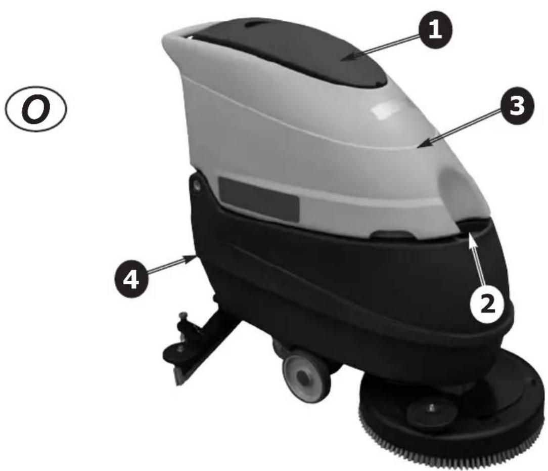
To access to the battery compartment, pull the opening lever (Photo H - 1) and lift the recovery tank (Photo O - 3).
Detach the spring clip (Photo I - 1) placed on the lifting cable of the brush plate.
Place the batteries in the battery compartment (Photo I - 2) checking that they are in perfect conditions.
5.1.4 BATTERY CONNECTION
(!) These operations must be carried out by specialized personnel.
Install and charge the batteries in a dry ventilated place, far from sources of heat and corrosive substances. Make sure that the voltage between the batteries and the battery charger corresponds. Protect the circuit with a delay switch or a fuse with a higher charge than the maximum absorption of the battery charger. Comply with the polarity of the battery plug.
Disconnect the Anderson connector of the battery wiring from the Anderson connector of the machine wiring (Photo D - 7) (Photo F - 8). Always hold the connectors with the hands and never pull on the cables.
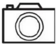
Photo G show connection diagram of the batteries for B - BT machines.
(✗) Attach the battery wiring to the battery, connecting the terminals only on the poles marked with the same symbol (red wiring "+", black wiring "-")!
A battery short-circuit may cause an explosion!
After checking that all the controls on the panel are in position "0" or at rest, connect the battery connector to the machine connector.
(!) Close the battery compartment making sure not to crush any wires.
Photo I - 3 show the correct connection of the batteries for B - BT machines.
5.1.5 CIRCUIT BOARD SETTINGS CONFIGURATION
The machine is equipped to GEL battery circuit board configured. If the operator whish to use e Pb-Acid battery, it is necessary to set the electronic circuit board as follows:
Model "B" (DC 24V)
(!) TO ENTER THE BATTERY THRESHOLD CONFIGURATION MODE:
1) Press simultaneously the push buttons "BRUSH MOTOR SWITCH" (Photo C - 1) and "SUCTION MOTOR SWITCH" (Photo C - 2) within 2 seconds after switching on the machine with the key switch (Photo D - 1). The three LED of the battery power test (Photo C - 3A, 3B, 3C) will be ON.
2) Press "SUCTION MOTOR SWITCH" key within 5 seconds from the previous action; you have now entered in the configuration mode: the green and yellow LED of the battery power test (Photo C - 3A, 3B) will be ON.
(!) THE CONFIGURATION SETTINGS ARE VISIBLE ON THE BRUSH MOTOR SWITCH SIGNAL LED (Photo C - 2A):
1) OFF: Pb-Acid.
2) ON: Gel.
(!) TO MODIFY CONFIGURATION SETTINGS: Press the "BRUSH MOTOR SWITCH" (Photo C - 1)
(!) TO SAVE THE SETTINGS AND EXIT THE MODE: Press the "SUCTION MOTOR SWITCH" (Photo C - 2)
Once the settings have been set, we have different battery discharge levels with differentiated intervention on the machine functions as specified in the following table:
Battery discharge indicator and functions - MODEL "B" (DC 24V)
| VoltsBattery Type | Battery power test indicator LED | Brush operation indicator LED | ||
| Pb-Acid GEL Signaling Signaling ACTION | ||||
| 24,0 24,0 | Green LED ON | LED ON All working | ||
| 21,5 22,5 | Yellow LED ON | LED ON All working | ||
| 20,5 21,5 | Red LED ON | LED FLASHING Brush | sh motor is not working | |
| 20,0 21,0 | Red LED | FLASHING | LED FLASHING Brush | brush and suction motors are not working |
Model "BT" (DC 24V with traction)
(!) TO ENTER THE BATTERY THRESHOLD CONFIGURATION MODE:
1) Press simultaneously the push buttons "REDUCE SPEED" (Photo E - 3) and "SUCTION MOTOR SWITCH" (Photo E - 6) within 2 seconds after switching on the machine with the key switch (Photo F - 1). The second LED of the speed indicator (Photo E - 3B) will be ON.
2) Press "INCREASE SPEED" (Photo E - 4)" key within 5 seconds from the previous action; you have now entered in the configuration mode.
(!) THE CONFIGURATION SETTINGS ARE VISIBLE ON THE SPEED INDICATOR LED:
1) The first two LEDs (Photo E - 3A, 3B) indicate the type of setting of the indicator intervention threshold an both must be ON;
2) The third and fourth LEDs (Photo E - 3C, 3D) indicate the battery type: for the PB-Acid battery only the third LED (Photo E - 3C) should be ON, while for the GEL battery both should be ON (Photo E - 3C, 3D)
(!) TO MODIFY CONFIGURATION SETTINGS:
1) The "INCREASE SPEED" (Photo E - 4)" and "REDUCE SPEED" (Photo E - 3) keys are used to set the indicator's intervention threshold in such a way that the first two speed indicators LEDs (Photo E - 3A, 3B) turn ON;
2) The "BRUSH MOTOR SWITCH" (Photo E - 5) is used to set the PB-Acid battery type while the "SUC-TION MOTOR SWITCH" (Photo E - 6) is used to set the GEL battery type
(!) TO SAVE THE SETTINGS AND EXIT THE MODE:
Press the "REDUCE SPEED" (Photo E - 3) switch and the "SUCTION MOTOR SWITCH" (Photo E - 6) simultaneously.
Once the settings have been set, we have different battery discharge levels with differentiated intervention on the machine functions as specified in the following table:
Battery discharge indicator and functions - MODEL "BT" (DC 24V with traction)
| VoltsBattery Type | Battery power test indicator LED | Brush operation indicator LED |
| Pb-Acid GEL Signaling | Signaling ACTION | ||
| 24,0 24,0 | Green LED ON | LED ON All working | |
| 21,5 | 22,5 | Yellow LED ON | LED ON |
| 20,5 | 21,5 | Red LED ON | LED FLASHING |
| 20,0 21,0 | Red | LED FLASHING | LED FLASHING |
If you do not complete the configuration procedure, the settings remain as they were originally.
(!) We recommend to call the assistance centre or a technician if you have problems with the settings given.
Do not open or tamper the electronic board.
(!) We recommend to call the assistance centre or a technician if you have problems with the setting given.
The machine is equipped with a battery charger configured for GEL batteries
If the operator whish to use Pb-Acid battery, it is necessary change the battery charger settings as follows:
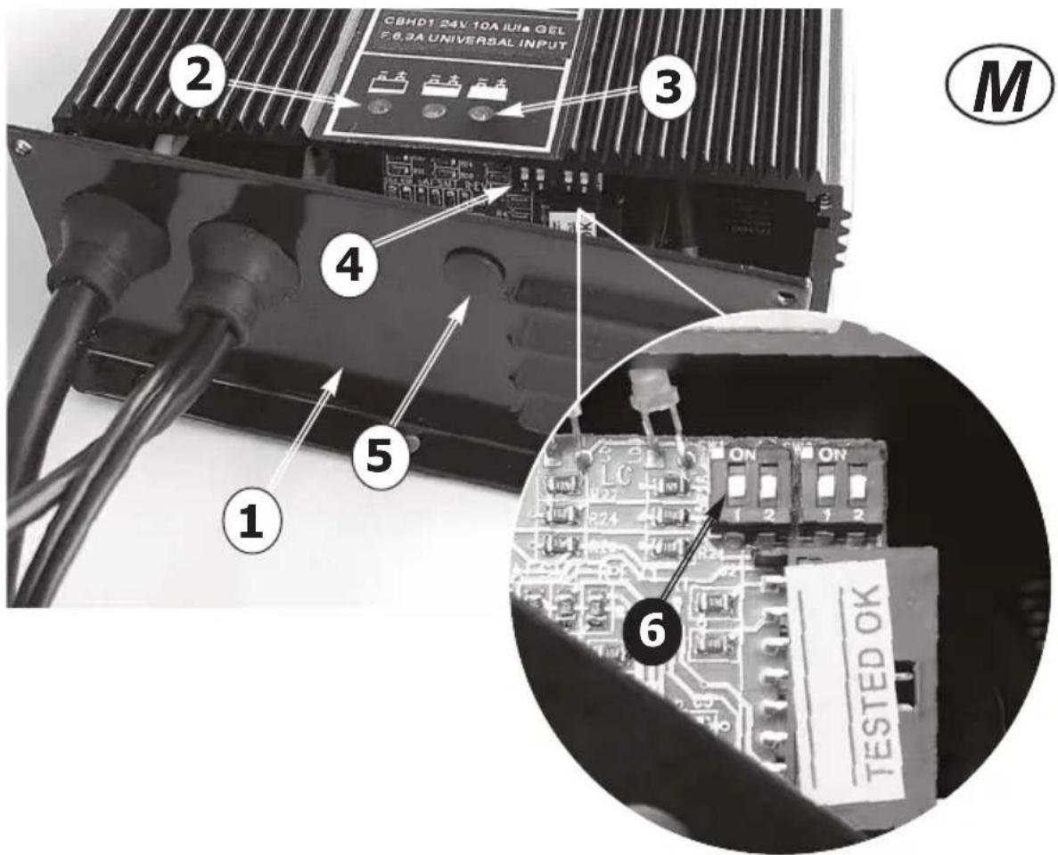
(!) DISPLAY OF THE BATTERY CHARGER SETTINGS
The battery charger settings are shown by the blinking of the LED indicator when the battery charger is switching on:
- the RED LED indicator ( Photo M - 2 )
flashes 2 times = the battery charger is set for PB-Acid batteries
- the GREEN LED indicator (Photo M - 3) flashes 2 times = the battery charger is set for GEL batteries
The battery charger settings will be displayed even if batteries are not connected.
( ! ) DIP-SWITCH CONFIGURATION FOR PC-ACID/GEL BATTERY CHARGING CURVE
To set the charging curve type for Pb-Acid or GEL batteries it is necessary to operate on a dip-switch placed inside the battery charger (
Photo M -4 ).
The dip-switch available for the setting of the charging curve is on the control card (Photo M - 4) that is placed behind the lower panel of the battery charger (Photo M - 1). It is also possible to reach the dip-switch by removing the plastic cap (Photo M - 5).
Starting from left to right, the dip-switch available for the setting of the charging curve is the first one, that is indicated by number 1 in dip-switch SW1 (Photo M - 6).
| Position of Dip-switch SW1 - number 1 | Charging curve |
| ON | Charging curve for PB-Acid batteries |
| OFF | Charging curve for GEL batteries |
NOTE: the position of all the remaining dip-switches must NOT be changed.
6. OPERATING INFORMATION 6.1 MACHINE PREPARATION
(!) Before starting to work, wear non-slip shoes, gloves and any other personal protection device indicated by the supplier of the detergent used or considered necessary based on the operating environment.
(☑) Do the following before starting to work. Refer to the relative sections for a detailed description of these steps:
Heck the battery charge level and charge, if necessary.
Mount the brushes or scraper disks (with the abrasive disks) that are suitable for the surface and work involved.
Mount the squeegee, check that it is solidly attached and connected to the suction hose and that the drying blades are not too worn.
Make sure that the recovery tank is empty. If not, empty it completely.
Check and completely close the detergent solution release control.
Fill the detergent solution tank with a mix of clean water and non-foaming detergent in an adequate concentration through the anterior hole. Leave 2 cm between the mouth of the plug and the level of the liquid.
( ) To avoid risks, become familiar with the machine movements, carrying out test runs on a large surface without obstacles.
To obtain the best results in terms of cleaning and equipment service life, you should do the following simple but important operations:
- Identify the work area, moving all possible obstacles out of the way; if the surface is very extensive, work in contiguous and parallel rectangular areas.
- Choose a straight work trajectory and begin working from the farthest area to avoid passing over areas that have already been cleaned.
6.2 STRUCTURE AND FUNCTIONS
PHOTO A Model E
1 GENERAL ON/OFF SWITCH
2 BRUSH MOTOR SWITCH
3 SUCTION MOTOR SWITCH
PHOTO B Model E
PHOTO E Model BT/T - (DC 24V with traction)
1 BATTERY POWER TEST
1A GREEN LED - FULL BATTERY CHARGE
1B YELLOW LED - 50% BATTERY CHARGE
1C RED LED - BATTERY DISCHARGED
2 FORWARD/REVERSE INDICATOR
3 REDUCE SPEED SWITCH
3A TRACTION SPEED 1
3B TRACTION SPEED 2
3C TRACTION SPEED3
3D TRACTION SPEED 4
4 INCREASE SPEED SWITCH
5 BRUSH MOTOR SWITCH
5A BRUSH MOTOR OPERATION LED
6 SUCTION MOTOR SWITCH
6A SUCTION MOTOR OPERATION LED
PHOTO F Model BT/T - (DC 24V with traction)
Model B - BT/T - (DC 24V without and with traction)
BATTERY CONNECTION DIAGRAM
PHOTO H
Model B - BT/T - (DC 24V without and with traction)
1 BATTERY COMPARTMENT OPENING LEVER
2 SOLUTION TANK FILLING OPENING
PHOTO I
Model B - BT/T - (DC 24V without and with traction)
1 OPENING CLIP SPRING
2 BATTERY COMPARTMENT WITH 12V BATTERIES
3 BATTERY CONNECTION WIRING
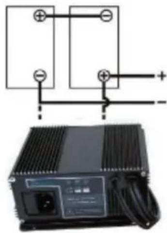
PHOTO L
Model B - BT/T - (DC 24V without and with traction)
1 BUILT-ON BATTERY CHARGER
2 BATTERY CHARGER POWER SUPPLY CABLE
PHOTO M
Model B - BT/T - (DC 24V without and with traction)
1 BATTERY CHARGER COVER
2 RED LED - BATTERY DISCHARGED
3 GREEN LED - FULL BATTERY CHARGE
4 DIP-SWITCHES
5 PLASTIC CAP
6 DIP-SWITCH NR. 1 FOR PB-ACID/GEL BATTERY SETTING
PHOTO N
Model E - B - BT/T
1 SQUEEGEE BUMPER WHEEL
2 SQUEEGEE PRESSION ADJUSTING KNOB
3 SUCTION HOSE
4 SQUEEGEE BLADES REPLACEMENT
KNOB
5 SQUEEGEE WHEEL
6 SQUEEGEE FIXING KNOB
7 SQUEEGEE INCLINATION ADJUSTING
KNOB
PHOTO O
Model E - B - BT/T
1 HOOD OF SUCTION FILTER COMPARTMENT
2 SOLUTION TANK FILLING OPENING
3 RECOVERY TANK
4 SOLUTION TANK
PHOTO P
Model E - B - BT/T
1 FLOATING DEVICE
2 SUCTION FILTER
3 RECOVERY TANK INSPECTION
PHOTO Q
Model E - B - BT/T
1 SOLUTION WATER FILTER AND WATER OUTFLOW ADJUSTING DEVICE
6.3 BATTERY CHARGING
Connect the patch cord to the power cable of the battery charger (Photo L - 2) and to the mains power.
On switching on a new battery charger of the CBHD1 series, the charger will check the battery voltage and decide whether to start the charging process. If the battery is not connected to the battery charger, the red LED will flash (Photo M - 2). If the result of the test is positive after 1 second the charging of the battery can start, with the red LED on.
The progress of the charging process is shown by three LED's: red, yellow and green, as in the whole range of the battery chargers.
The green LED (Photo M - 3) shows the end of the charging or the last phase in case of deep charging process; in the former case, the relay is opened to disconnect galvanically the battery from the battery charger.

(!) For further information refer to the use and safety manual of the battery charger provided by the manufacturer.
If the machine is equipped with Pb-Acid batteries, charge only in a well-ventilated area, lift the superior cover and open the battery plugs.
(✗) Follow the steps indicated in the battery manufacturer's operating and safety manual (see the battery maintenance section).
If the machine is equipped with GEL batteries (maintenance free), follow the instructions indicated here below.
If the machine is used regularly:
Always keep the batteries connected to the battery charger when the machine is not being used.
If the machine is not used for extended time periods:
Charge the battery during the night after the last work period, and then disconnect the battery from the battery charger.
Charge the battery during the night before using the machine again.
Intermediate or incomplete charging while working should be avoided.
If the machine is equipped with Pb-Acid batteries, use a hydrometer to check the element liquid intensity on a regular basis: if one or more elements are discharged and the others fully charged, the battery has been damaged and should be replaced or repaired (refer to the battery service manual).
Close the element plugs and lower the superior cover.
6.4 SQUEEGEE ASSEMBLY
Slightly screw the two knobs (Photo N - 6) into the squeegee body and insert the squeegee into the slots situated on the squeegee support.
Screw the two knobs (Photo N - 6) in order to secure the squeegee to the support.
Firmly insert the suction hose (Photo N - 3) into the pipe in the squeegee body.
6.5 SQUEEGEE DISASSEMBLY
Disconnect the suction hose from the squeegee
body.
Unscrew the two knobs (Photo N - 6) that secure the squeegee to its support and pull the squeegee to free it.
6.6 SQUEEGEE BLADES DISASSEMBLY / ASSEMBLY
Disassemble the squeegee from its support (see 6.5)
Unscrew the knobs (Photo N - 4, N - 6) placed on the squeegee body and apply some pressure on their bolts in order to push out the plastic support of the squeegee blades from the squeegee body.
Tear off the rubber blades from the plastic support. Assemble the new blades on the plastic support by the means of the plastic pins that have to be fixed in the holes placed the blades.
Push the plastic support of the squeegee blades into the squeegee body and screw the knobs (Photo N - 4, N - 6) to secure it to the squeegee body.
Reassemble the squeegee to its support (see 6.4).
6.7 SQUEEGEE ADJUSTMENT
The knob screw on the squeegee support (Photo N - 7) adjusts the squeegee's inclination with respect to the floor. The two red knobs on the sides, connected to the rear wheels of the squeegee (Photo N - 2) are to adjust the pressure of the squeegee to the floor.
When the squeegee is perfectly adjusted, the rear squeegee blade, sliding as it moves, bends in all points forming an angle of 45^ with the floor.
As the machine operates (advances), the knobs (Photo N - 2, N - 7) can be used to adjust the inclination and pressure of the squeegee blades on the floor.
Squeegee drying must be uniform along the entire drying line: damp patches mean that drying is insufficient; turn the adjustment knobs to optimize drying.
6.8 SPLASH GUARD ASSEMBLY/ DISASSEMBLY
The splash guard is assembled to the brush plate with a spring holder linked to the brush plate itself. To disassemble the splash guard simply detach the spring holder and pull the splash guard.
To reassemble, fix the splash guard in the brush plate, and then hook the steel cable to one side of the plate and the spring holder to the other side of the brush plate.
6.9 BRUSH ASSEMBLY / DISASSEMBLY
(!) Never use the machine if the brush or the pad holder with abrasive pad is not perfectly installed.
Assembly:
Make sure that the brush plate is raised; otherwise lift it by following the instructions provided in the specific section.
Make sure that the ignition key on the control panel is in OFF position.
Place the brush under the plate, taking care that the coupling flange on the brush is under the metal coupling of the machine.
Lower the brush plate and start the brush rotation operating the brush motor switch and the brush operation lever; the brush will couple automatically.
To assemble the pad holder follow the same procedure.
(!) Do not allow the length of the rows of brushes to become lower than 1 cm.
(!) Do not allow the thickness of the abrasive disks to become less than 1 cm.
Working with excessively worn brushes or excessively thin abrasive disks may damage the machine and the floor.
Regularly check the wear on these parts before starting to work.
Disassembly or replacement:
Make sure that the brush plate is raised; otherwise lift it by following the instructions provided in the specific section.
Make sure that the ignition key on the control panel is in position OFF position.
While holding the brush with the hands under the plate, turn it in the rotation direction while lowering to release it from the metal coupling on the machine.
To disassemble the pad holder follow the same procedure.
6.10 FILLING AND DRAINING THE SOLUTION TANK
( ) The temperature of the water or the detergent should never exceed 50°C.
( )Always empty the recovery tank ( Photo O - 4) before filling the solution tank ( Photo O - 3).
To fill the tank:
- Pour into the tank the required quantity of the chemical product, considering the percentage indicated by the supplier, with reference to the full tank capacity listed on the product sheet.
(!) Use only those products suitable for the floor and the dirt to be removed.
- Pour water in the filling opening placed in the front of the machine (Photo H - 2, O - 2).
Leave 2 cm between the filling opening and the liquid level. Do not fill beyond this point!
(✗) The machine was designed to be used with non-foaming and biodegradable detergents made specifically for scrubber-driers.
The use of other chemical products (such as sodium hypochlorite, oxidizers, solvents or
hydrocarbons) may damage or destroy the machine.
- Follow the safety regulations specified in the relative section and indicated on the detergent container.
- Contact the machine manufacturer to obtain a complete list of available and suitable detergents.
- Do not leave the water hose unattended and insert it completely into the tank: the hose might move and get sensitive parts of the machine wet. Close the tank with its foam plug.
To drain the tank:
- Unscrew and remove the transparent cap of filter /regulator of the cleaning solution placed in the bottom of the tank (Photo Q - 1) and wait for the complete emptying.
- After draining, replace and tighten the cap.
6.10.1 ADJUSTING THE OUTFLOW OF THE CLEANING SOLUTION
The solution water filter (Photo Q - 1) also has the function as a regulator of the flow of the cleaning solution; screwing the transparent cover increases the amount of flow, while unscrewing the lid reduces the flow.
6.11 DRAINING THE RECOVERY TANK
The dirty water must be drained in accordance with national regulations.
The user is completely responsible for ensuring compliance with such rules.
After the detergent solution is finished, always empty the recovery tank (Photo O - 3) before filling it again.
In general, the recovery tank can be emptied whenever required, and even during intermediate phases of the work cycle.
The recovery tank volume is higher than the detergent solution volume, therefore a potentially dangerous situation for the suction motor should never occur. In any case, a safety float (Photo P - 1) will stop the suction if the dirty liquid level is too high.
(✗) If water or foam starts leaking from under the tanks for any reason, immediately turn off the suction motor and empty the recovery tank.
To drain the tank:
Drive the machine to a suitable location to drain the dirty water and preferably near a toilet or a sewer drain (comply with the national regulations for waste water disposal).
Turn off the machine and remove the key from the panel.
Detach the drain hose from the holder (Photo B - 5, D - 6, F - 7) and, keeping it high, unscrew the plug.
Lower the drain hose toward the selected drainage point.
The emptying operation can be interrupted quickly and whenever required just by raising the drain hose.
Check how much dirt is still in the tank and, if necessary, wash it inside through the inspection hole (Photo P - 3).
Fully tighten the drain hose with the screw plug and hang it on the support behind the machine. The drain hose plug must be airtight, otherwise the subsequent pressure loss will reduce drying efficiency.
6.12 SPECIFIC INSTRUCTIONS FOR THE USE OF MODEL AC 230V
The AC 230V model machine may be turned on only if the voltage indicated on the tag corresponds with the available voltage and that the electrical outlet is grounded (earthed).
Do not damage the feed cable; do not crush or pull on it.
Do not run over the feed cable with the machine. The cable could wind up in moving parts causing a short circuit.
(✗) ATTENTION !!! - The model AC 230V machine has parts, which are connected to the current; contact with these could cause grave injuries or even death.
- Before executing any type of operation on the machine always disconnect it from the electrical source.
- Never touch electric cables that are defective or worn.
- Before gaining access to the electrical system it is always necessary to disconnect the machine from the electrical source.
- In the case of defective, damaged, or cracked electric cables, replace immediately with authentic replacement parts.
- The network of connections must be protected from water spray.
- The patch cord for the connection of the machine to the mains power must conforms to current safety rules.
- The electrical system to which the machine is connected must be equipped with a cutout box.
- It is absolutely forbidden to use the machine in proximity to swimming pools or stretches of water.
(✗) EMERGENCY SITUATIONS
In case of emergency:
- Immediately disconnect the machine from the power mains.
- Immediately apply proper first-aid.
If an accident should occur the machine must not be put into operation until a technician authorized by the manufacturer has examined it.
6.13 DRIVING THE MACHINE Model AC 230V
- Connect the power cable of the machine (Photo B - 1) to the power mains using a patch cord.
- Switch ON the general ON-OFF switch (Photo A - 1).
- Switch ON the brush motor switch (Photo A - 2).
( ! ) The brush will start the rotation only when the machine operator will operate the brush operation lever ( Photo B - 4).
- Switch ON the suction motor switch (Photo A - 3).
- Lower the squeegee unit by using the lift/lower lever (Photo B - 3)
- Lower the brush plate unit by using the lift/lower lever (Photo B - 2)
- Wash the floor moving forward slowly, pulling the brush operation lever (Photo B - 4); releasing the lever the brush rotation will stop after few seconds.
To adjust the outflow of the cleaning solution it is necessary to act on cap of the solution water filter (Photo Q - 1); screwing the transparent cap increases the amount of flow, while unscrewing the cap reduces the flow.
(!) Remember to lift the squeegee before driving reverse to avoid damaging it.
Model DC 24V
- Verify that the battery connector placed in the back of the machine (Photo D - 7) is connected.
- Put the ignition key (Photo D - 1) in and turn ON the machine.
- In the control panel, check the battery charge status (Photo C - 3)
- Switch ON the brush motor switch (Photo C - 1).
(!) The brush will start the rotation only when the machine operator will operate the brush operation lever (Photo D - 2).
- Switch ON the suction motor switch (Photo C - 2).
- Lower the squeegee unit by using the lift/lower lever (Photo D - 4)
- Lower the brush plate unit by using the lift/lower lever (Photo D - 3)
- Wash the floor moving forward slowly, pulling the brush operation lever (Photo D - 2); releasing the lever the brush rotation will stop after few seconds.
To adjust the outflow of the cleaning solution it is necessary to act on cap of the solution water filter (Photo Q - 1); screwing the transparent cap increases the amount of flow, while unscrewing the cap reduces the flow.
(!) Remember to lift the squeegee before driving reverse to avoid damaging it.
Model DC 24V with traction
- Verify that the battery connector placed in the
back of the machine ( Photo F - 8) is connected.
- Put the ignition key (Photo F - 1) in and turn ON the machine.
- In the control panel, check the battery charge status (Photo E - 1) and, if sufficient, select the running speed wished (Photo E - 3, E - 4).
-
Switch ON the brush motor switch (Photo E - 5). (!) The brush will start the rotation only when the machine operator will operate the brush operation lever (Photo F - 2).
-
Switch ON the suction motor switch (Photo E - 6).
- Lower the squeegee unit by using the lift/lower lever (Photo F - 4)
- Lower the brush plate unit by using the lift/lower lever (Photo F - 3)
- Wash the floor moving forward by pulling the traction lever (Photo F - 2) up or push the traction lever down to reverse traction; releasing the lever the traction will stop immediately and brush rotation will stop after few seconds.
To adjust the outflow of the cleaning solution it is necessary to act on cap of the solution water filter (Photo Q - 1); screwing the transparent cap increases the amount of flow, while unscrewing the cap reduces the flow.
(!) Remember to lift the squeegee before driving reverse to avoid damaging it.
6.14 WORK METHOD
6.14.1 PREPARATION AND WARNINGS
Remove any loose solid residue from the surface to be treated (using suitable tools, such as vacuum cleaners, sweepers, etc.). It this is not done, the solid dirt might prevent the squeegee from operating correctly, reducing drying efficiency.
Only trained personnel can drive this machine.
6.14.2 BATTERY CHARGE LEVEL CONTROLS
The sequence of lights of the battery charge control (Photo C - 3, E - 1) progressively turns off until the battery is discharged. When the red light turns on (Photo C - 3C, E - 1C), turn off the brush motor, close the detergent solution outlet, finish drying the small residual moisture and go to the battery charging area to charge the battery.
(!) The batteries may be irreparably damaged if the residual charge level drops too low (see the battery operating manual). Do not force the battery discharge beyond the safety limits, turning the key off and on or in any other manner.
6.14.3 DIRECT SCRUBBING OR FOR SLIGHTLY DIRTY SURFACES
Scrubbing and drying in a single pass.
Prepare the machine as previously described and use it as described in paragraph 6.13.
(✗) Never use the machine without the detergent solution: the floor might be damaged.
6.14.4 INDIRECT SCRUBBING OR FOR VERY DIRTY SURFACES
Scrubbing and drying in various passes.
Prepare the machine as previously described.
First set of operations:
Wash the floor as described in paragraph 6.13, without drying the floor
Allow the detergent solution to work on the dirty floor according to what is indicated in the information relative to the detergent used.
Second set of operations:
Proceed as explained in the previous "Direct Washing" paragraph (6.14.3) to also proceed with drying the floor.
(☑) Never use the machine without the detergent solution: the floor might be damaged.
6.14.5 POST-SCRUBBING OPERATIONS
Close the detergent solution outlet.
Lift the brush unit and turn off the brush motor.
After having completely dried any traces of water on the surface, wait a few seconds and then lift the squeegee and turn off the suction motor.
Move to a suitable location to drain the tanks; empty and clean the tanks (as described in 6.11).
Turn off the machine using the key and remove it from the control panel.
If necessary, charge the battery (see the relative section).
7. MAINTENANCE INFORMATION
(✗) Turn the key, remove it from the control panel and disconnect the battery from the machine wiring.
(☑) All work on the electrical system as well as all maintenance and repair operations (especially those not explicitly described in this manual) should be carried out only by authorized service centers or by specialized technical personnel who are experts in the sector and in the pertinent safety regulations.
Performing regular maintenance on the machine, and carefully following the manufacturer's instructions, is the best guarantee for obtaining the best performances and extended machine service life.
7.1 TANKS
Drain the two tanks as described in the relative sections.
Remove any solid dirt by filling and draining the tanks until all dirt has been eliminated: use a washing hose or similar tool to do this.
(!) Water hotter than 50°, a high-pressure cleaner or excessively powerful sprays may damage the tanks and the machine.
Leave the plugs of the tanks open (only while the machine is not being used) so that they can dry and thus prevent the formation of foul odors.
7.2 SUCTION HOSE
Detach the suction hose from the squeegee (Photo N - 3).
Now you can wash the hose and remove any obstructions.
Firmly insert the hose on the squeegee body.
7.3 SQUEEGEE
(!) Do not handle the squeegee with bare hands: wear gloves and any safety clothing needed to carry out the operation.
Detach the squeegee from the machine and clean it under running water using a sponge or a brush.
Check the efficiency and the wear on the strips in contact with the floor. They are designed to scrape the film of detergent and water on the floor and to isolate that portion of the surface to enhance the vacuum of the suction motor: this ensures that the machine will dry very efficiently. Working constantly in this manner tends to round or to deteriorate the sharp edge of the strip, thus reducing drying efficiently. This is why the squeegee strips must be replaced.
To replace the worn blades, follow the instructions in the relative section. Turn the blades around to wear down the other sharp corners or to install new ones.
7.4 ACCESSORIES
Remove and clean the brushes or the scraper disks. (!) To avoid damaging the floor and the machine, carefully check if foreign matter, such as metallic parts, screws, chips, cords or similar items, has become jammed.
Check that the brushes are flat as they work on the surface (check for any irregular wear on the brushes or on the abrasive disks). If necessary, adjust the slant of the action on the floor.
Use only the accessories recommended by the manufacturer: other products may reduce operating safety.
7.5 MACHINE BODY
Use a sponge or a soft cloth to clean the exterior of the machine and, if necessary, a soft brush to eliminate tough dirt. The machine's shockproof surface is rough to make it harder to see scratches caused during use. However, this does not make it easier to remove tough stains on the surface. It is prohibited to use steam machines, hoses with running water and high-pressure cleaners.
7.6 BATTERIES
PB-Acid batteries
Carry out maintenance operations in accordance with the manufacturer's instructions and with all the
other instructions provided in this manual.
Exposing the element plates (not completely immersed in the acid solution) will lead to rapid oxidation and irreparably reduce the element's operating capacities.
An overflowing acid solution may corrode the machine.
Use battery chargers recommended by the manufacturer and, in any case, those that are suitable for the type of battery to be charged.
Always charge batteries in well-ventilated rooms: there is an explosion risk!
The use of gel or maintenance-free batteries is highly recommended.
GEL batteries
Carry out maintenance operations in accordance with the manufacturer's instructions and with all the other instructions provided in this manual.
Use only those battery chargers recommended by the manufacturer.
7.7 THERMAL BREAKERS
The machine is equipped with electric protection devices on the main operating components to avoid costly malfunctions.
Thermal breakers are installed to protect the drive motor wherever foreseen and the brush motor.
When one of these breakers trips automatically, the disabled function can be reactivated by fully depressing the button of the breaker.
When the thermal breakers trip, especially when the machine is used during the first few weeks, it might not be caused by actual machine malfunctions. However, a specialized technician should check the device if the relative breaker continues to trip.
7.8 PERIODIC MAINTENANCE
For all the operations described herein, refer to the instructions and detailed warnings in the relative sections.
7.8.1 DAILY OPERATIONS
Disassemble and check the brush or the pad driver disk (with the abrasive disks mounted).
Check that there are no foreign bodies that may impede the movement or efficiency of all cleaning parts.
Check the squeegee: clean the blades and check their condition/wear.
If Pb-Acid batteries are used, carefully carry out the operations described by the battery manufacturer. Charge the batteries.
7.8.2 WEEKLY OPERATIONS
Check and, if necessary, replace the splash guard. Carefully check the profile of the squeegee blades and replace them, if necessary.
Check that the suction hoses and conduits are not clogged;
Thoroughly clean the solution and recovery tanks. For other models with the Pb-Acid battery: check the level of the electrolyte in all elements and, if necessary, top up with distilled water. Refer to the battery manufacturer's detailed instructions.
Lift the filter compartment cover and check under the impermeable sponge filter for any signs of liquid; if there is any, drain it off into the dirty water tank.
7.8.3 OPERATIONS AT EXTENDED INTERVALS
Even though the machine was built with great precision and conforms to the most severe quality tests, the electrical and mechanical parts will inevitably be subjected to wear and aging after extended periods of use.
For safe and problem-free operation, your machine should be carefully checked every year by our authorized technical service centre (or by a specialist in the sector familiar with all the pertinent safety regulations contained in this manual).
This type of work may have to be carried out more frequently if the machine operates in particular/difficult situations and/or if required maintenance was not performed.
7.9 RECOMMENDED SPARE PARTS
You'll always be able to use your machine as efficiently as possible by maintaining a stock of the most common consumable materials and by scheduling routine and extraordinary maintenance. Contact your dealer for a list of these spare parts.
8. OPERATING CHECKS
8.1 THE MACHINE DOESN'T WORK
😊 The key isn't inserted or correctly turned.
Insert and turn the key to position ON.
The battery connector is disconnected or poorly attached to the main wiring connector.
😊 Firmly connect the two connectors.
😊The machine is charging.
😊 Complete the charging operation.
😊 The batteries are discharged.
😊 Charge the batteries.
8.2 THE MACHINE DOESN'T MOVE
😊 The traction lever is in neutral position.
☺ Select a traction direction by pulling or pushing the traction lever.
😊 The floor slope is too high.
😊 Push manually the machine to the upper floor level.
The thermal protection of the traction motor is tripped.
Stop the machine and rest it for 5 minutes, the push the thermal breaker button.
😊 The batteries are discharged.
😊 Charge the batteries.
8.3 THE BRUSH DON'T ROTATE
😊 The brush motor switch is not selected.
😊 Press the button to activate the brushes.
The brush motor thermal breaker tripped; the motor overheated.
😊 Troubleshoot the cause (cords or similar items that impede movement, surface too rough, etc.) and press the reset breaker (the first from the top).
😊 The transmission belt is broken.
😊 Replace it.
The motor relay or the brush motor is broken.
😊 Replace it.
8.4 NOT ENOUGH OR TOO MUCH DETERGENT
The detergent solution tank is empty.
😊 Fill the detergent solution tank after having emptied the recovery tank.
😊 The flow adjustment lever is closed or almost closed.
😊 Adjust/increase the detergent solution outlet flow as required.
😊 The detergent feed conduit is clogged in some point.
😊 Clean out the conduit by removing the dirt.
8.5 NO SUCTION
😊 The suction hose is not connected to the squeegee.
😊 Connect it correctly.
The suction hose or the squeegee conduit are clogged.
😊 Clean out and remove any obstructions from the conduits.
😊 The suction motor is turned off.
😊 Activate it.
😊 The recovery tank is full.
😊 Empty it.
😊 The suction motor is not receiving electric power or is burned.
😊 Check the connections and, for the latter case, replace the motor.
8.6 INSUFFICIENT SUCTION
The recovery tank drain hose plug is not perfectly closed.
😊 Close it correctly.
The suction hose, the squeegee conduit or the inspection compartment is clogged.
😊 Clean out and remove any obstructions from the conduits.
8.7 THE BRUSH MOTOR OR THE SUCTION MOTOR DOESN'T STOP
Stop the machine, cutting off the main power supply and disconnecting the main battery connector, and contact the technical service centre.
8.8 THE SQUEEGEE DOESN'T CLEAN OR DRY EFFICIENTLY
😊 The squeegee blades are worn or are dragging solid dirt.
😊 Replace or clean them.
The squeegee adjustment is not correct; the advancement must be exactly perpendicular to the running direction.
😊 Adjust the squeegee.
The suction hose or the squeegee conduit are clogged.
😊 Clean out and remove any obstructions from the conduits.
8.9 THE BATTERY CHARGER DOESN'T WORK
😊 The battery charge doesn't start.
😊 Check that the battery charger is connected to the battery. Consult the battery charger manual.
8.10 THE BATTERIES DO NOT CHARGE OR DO NOT HOLD A CHARGE
At the end of the charging process, the battery is not correctly charged (see the battery manufacturer's instruction-maintenance manual)
◎ Check the battery charger error message and check the data indicated on the display (see the battery charger's instruction manual).
😊 The batteries are new and do not generate 100% of the rated performances.
😊 The accumulator reaches the maximum performance after 20-30 complete charge cycles.
The electrolyte has evaporated and does not completely cover the plates.
😊 Check the battery manufacturer's use and maintenance manual.
There are significant differences in density among the various elements.
😊 Replace the damaged battery.
Always consult the battery and battery charger use and maintenance manual. If this does not solve the problem, contact the authorised technical service centre.
The manufacturer CANNOT solve problems caused by using batteries and battery chargers that were not directly supplied.

natural_image
French flag icon showing blue and red vertical stripes (no text or symbols)1. SOMMAIRE
2. GENERALITES
2.1 BUT DU MANUEL
2.2 TERMINOLOGIE ET
LEGENDE DES SYMBOLES
2.3 IDENTIFICATION DE LA MACHINE
2.4 USAGE PREVU
2.5 MODIFICATIONS TECHNIQUES
3. INFORMATIONS SUR LA SECURITE
3.1 REGLES IMPORTANTES
3.2 EMISSION SONORE ET VIBRATIONS
4. INFORMATIONS SUR LA MANUTENTION
4.1 MANUTENTION DE L'EMBALLAGE
4.2 CONTROLE A LA RECEPTION
4.3 DEBALLAGE
4.4 MANUTENTION DE LA MACHINE, DES BATTERIES ET DU CHARGEUR DE BATTERIES
5. INFORMATIONS TECHNIQUES
5.1 BATTERIES
5.1.2 PREPARATION DES BATTERIES
5.1.3 INSTALLATION DES BATTERIES
5.1.4 BRANCHEMENT DES BATTERIES
5.1.5 CONFIGURATION DE L'INDICATEUR DE LA DÉCHARGE DES BATTERIES
5.2 CONFIGURATION DU CHARGEUR DE BATTERIES
6. INFORMATIONS SUR L'UTILISATION
6.1 PREPARATION DE LA MACHINE
6.2 STRUCTURE ET FONCTIONS DE LA MACHINE
6.3 RECHARGE DES BATTERIES
6.4 MONTAGE DU SUCEUR
6.5 DEMONTAGE DU SUCEUR
6.6 REMPLACEMENT DES BAVETTES DU SUCEUR
7.5 CORPS DE LA MACHINE
7.6 BATTERIES
7.7 DISJONCTEURS THERMIQUES
7.8 CADENCES
4. INFORMATIONS SUR LA MANUTENTION
4.1 MANUTENTION DE L'EMBALLAGE
7.5 CORPS DE LA MACHINE
natural_image
waving flag of Germany in red, yellow, and black (no text or symbols)4. HANDLING-INFORMATIONEN
4. HANDLINGS-INFORMATIONEN
natural_image
Abstract wavy flag design in red and yellow gradients (no text or symbols)1. INDICE
2. INFORMACIONES GENERALES
1B INDICADOR LUMINOSO LED AMARILLO BATERÍAS CARGA 50%
1C INDICADOR LUMINOSO LED ROJO BATERÍAS DESCARGA
natural_image
Simple line drawing of a trash bin with crossed lines indicating no waste or discharge (no text or symbols)
natural_image
Simple line drawing of a trash bin with crossed lines indicating no waste or discharge (no text or symbols)

Italiano
As owner of an electrical or electronic product, you are not allowed by law (according to EU-Directive 2002/96/EC of 27 January 2003 on waste electrical and electronic equipment and the particular national laws of the EU-Member States transforming this Directive) to dispose of this product or its electrical/electronic accessories as unsorted domestic waste. You shall use the designated gratis possibilities for return instead.
Français
natural_image
Abstract wavy flag design with red and blue stripes (no text or symbols)Conditions of Warranty
All our appliances are subjected to rigorous tests and are covered by warranty against material or manufacturing defects for a period of 12 months. The warranty comes into effect from the date of purchase. The date of purchase is the date indicated on the receipt issued by the Reseller when the appliance is consigned. The manufacturer shall repair or replace any faulty parts free of charge during the period covered by the warranty. Any defects, which cannot be clearly attributed to material or manufacturing defects shall be examined by one of our Technical Service Centres or at our factory and charged in accordance with the outcome. The following are anyhow not covered by the warranty: accidental damage during transportation or handling, accidental damage caused by negligence or unsuitable conduct, damage due to incorrect or improper uses or installations which do not conform with the warnings included in the instruction manual, and anyhow due to unusual events which do not depend on the running or use of the appliance. Appliances requiring repair must be delivered at the Technical Service Centre complete with all their original accessories together with proof of purchase. If the appliance has been repaired or tampered with by unauthorised third parties, the warranty shall be considered null and void. The warranty shall also be considered null and void if the user is not able to produce an original (legible and complete) document proving purchase or if it not possible to read the appliance serial number located on the frame. The appliance shall not be replaced and the warranty shall not be extended once the appliance has been affected by a fault. Repairs shall be carried out at one of our Authorised technical Service Centres or at our factory. Appliances for repair must be sent carriage free, that is, the user shall pay and be responsible for carriage. The warranty does not cover the cleaning of working parts, any scheduled maintenance nor the repair or replacement of parts subject to normal wear and tear. The manufacturer shall not be held liable for damage into persons or things caused by any installation which does not comply with the instructions in the manual or faulty use of the appliance.

natural_image
Two abstract colored shapes: a blue gradient rectangle and a red gradient rectangle, with no text or symbols.Conditions de garantie
natural_image
Abstract wavy gradient background with red, yellow, and pink hues (no text or symbols)K (uncertainty) ±1dB (A)
IT Livello di potenza sonora garantito
EN Acoustic power granted
FR Niveau du puissance sonore garanti
DE Garantiertes Schalleistungsniveau
ES Nivel de potencia acústica garantido
RU Акустическая мощность предоставлено
LwA 80 dB(A)
Vibrazioni trasmesse all'utilizzatore
EN Vibrations
FR Vibrations transmises à l'utilisateur
DE Effektivbeschleunigung Vibrationswert
ES Vibraciones transmitidas al usuario
RU Вибрации, передаваемые пользователю
0,14 m/s ^2 (±15%)
CE
IT CERTIFICATO CE DI CONFORMITÀ
EN CE CERTIFICATE OF CONFORMITY
FR CERTIFICAT CE DE CONFORMITÉ
EN Declares under its responsibility that the machine:
EN PRODUCT: FLOOR SCRUBBER
FR PRODUIT: AUTOLAVEUSE
EN complies with directives EC, and subsequent modifications, and the standards EN:
EN Technical booklet at


- E - B - BT/T
- INDICE
- CONTENTS
- GENERAL INFORMATION
- SAFETY INFORMATION
- HANDLING INFORMATION
- INSTALLATION INFORMATION
- MAINTENANCE INFORMATION
- OPERATING CHECKS
- GENERAL INFORMATION 2.1 SCOPE OF THE MANUAL
- TERMINOLOGY AND SYMBOL LEGEND
- PRODUCT IDENTIFICATION
- SPECIFIC USE
- TECHNICAL MODIFICATIONS
- BASIC RECOMMENDATIONS
- NOISE AND VIBRATIONS
- PACKING LIFTING AND TRANSPORT
- CHECKS UPON DELIVERY
- UNPACKING
- LIFTING AND TRANSPORT: MACHINE, BATTERY AND BATTERY CHARGER
- INSTALLATION INFORMATION 5.1. BATTERY
- BATTERY PREPARATION
- BATTERY INSTALLATION
- BATTERY CONNECTION
- CIRCUIT BOARD SETTINGS CONFIGURATION
- Model "B" (DC 24V)
- Model "BT" (DC 24V with traction)
- Battery discharge indicator and functions - MODEL "BT" (DC 24V with traction)
- Photo M -4 ).
- OPERATING INFORMATION 6.1 MACHINE PREPARATION
- STRUCTURE AND FUNCTIONS
- PHOTO A Model E
- PHOTO B Model E
- PHOTO E Model BT/T - (DC 24V with traction)
- PHOTO F Model BT/T - (DC 24V with traction)
- PHOTO H
- PHOTO I
- PHOTO L
- BATTERY CHARGER POWER SUPPLY CABLE
- PHOTO M
- Model B - BT/T - (DC 24V without and with traction)
- PHOTO N
- Model E - B - BT/T
- PHOTO O
- PHOTO P
- PHOTO Q
- BATTERY CHARGING
- SQUEEGEE ASSEMBLY
- SQUEEGEE DISASSEMBLY
- SQUEEGEE BLADES DISASSEMBLY / ASSEMBLY
- SQUEEGEE ADJUSTMENT
- SPLASH GUARD ASSEMBLY/ DISASSEMBLY
- BRUSH ASSEMBLY / DISASSEMBLY
- FILLING AND DRAINING THE SOLUTION TANK
- hydrocarbons) may damage or destroy the machine.
- To drain the tank:
- ADJUSTING THE OUTFLOW OF THE CLEANING SOLUTION
- DRAINING THE RECOVERY TANK
- SPECIFIC INSTRUCTIONS FOR THE USE OF MODEL AC 230V
- (✗) ATTENTION !!! - The model AC 230V machine has parts, which are connected to the current; contact with these could cause grave injuries or even death.
- (✗) EMERGENCY SITUATIONS
- In case of emergency:
- DRIVING THE MACHINE Model AC 230V
- Model DC 24V
- Model DC 24V with traction
- WORK METHOD
- PREPARATION AND WARNINGS
- BATTERY CHARGE LEVEL CONTROLS
- DIRECT SCRUBBING OR FOR SLIGHTLY DIRTY SURFACES
- INDIRECT SCRUBBING OR FOR VERY DIRTY SURFACES
- Allow the detergent solution to work on the dirty floor according to what is indicated in the information relative to the detergent used.
- POST-SCRUBBING OPERATIONS
- TANKS
- SUCTION HOSE
- SQUEEGEE
- ACCESSORIES
- MACHINE BODY
- BATTERIES
- GEL batteries
- THERMAL BREAKERS
- PERIODIC MAINTENANCE
- DAILY OPERATIONS
- WEEKLY OPERATIONS
- OPERATIONS AT EXTENDED INTERVALS
- RECOMMENDED SPARE PARTS
- THE MACHINE DOESN'T WORK
- THE MACHINE DOESN'T MOVE
- THE BRUSH DON'T ROTATE
- NOT ENOUGH OR TOO MUCH DETERGENT
- NO SUCTION
- INSUFFICIENT SUCTION
- THE BRUSH MOTOR OR THE SUCTION MOTOR DOESN'T STOP
- THE SQUEEGEE DOESN'T CLEAN OR DRY EFFICIENTLY
- THE BATTERY CHARGER DOESN'T WORK
- THE BATTERIES DO NOT CHARGE OR DO NOT HOLD A CHARGE
- SOMMAIRE
- GENERALITES
- INFORMATIONS SUR LA SECURITE
- INFORMATIONS SUR LA MANUTENTION
- INFORMATIONS TECHNIQUES
- INFORMATIONS SUR L'UTILISATION
- MANUTENTION DE L'EMBALLAGE
- CORPS DE LA MACHINE
- HANDLING-INFORMATIONEN
- HANDLINGS-INFORMATIONEN
- INFORMACIONES GENERALES
- Italiano
- Français
- Conditions of Warranty
- Conditions de garantie
- CE
Brand : Lavor
Model : A5 EVO 50E
Category : Tumble dryer