— Motorcycle — Mode d'emploi PDF")
CityCorp 125cc (2008) - Motorcycle Sherco - Free user manual and instructions
Find the device manual for free CityCorp 125cc (2008) Sherco in PDF.

User questions about CityCorp 125cc (2008) Sherco
0 question about this device. Answer the ones you know or ask your own.
Ask a new question about this device
Download the instructions for your Motorcycle in PDF format for free! Find your manual CityCorp 125cc (2008) - Sherco and take your electronic device back in hand. On this page are published all the documents necessary for the use of your device. CityCorp 125cc (2008) by Sherco.
USER MANUAL CityCorp 125cc (2008) Sherco
natural_image
Close-up of a black and white off-road vehicle with visible engine compartment and tire tracks (no text or symbols)
natural_image
Close-up of a motorcycle's internal engine bay showing pistons, gears, and motors (no text or symbols visible)
natural_image
Close-up of a bicycle wheel with a metallic suspension and mechanical component (no visible text or symbols)SHERCO
Motorcycles
SHE
INDEX
FRANCAIS
P.04

P.29
ENGLISH
P.31

P.57
ESPAÑOL
P.59

P.85
natural_image
Close-up of a mechanical knob with labeled points A and B, showing a circular dial and pointer (no text or symbols beyond labels)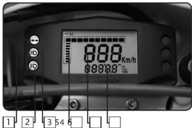
Contacteur à clef
natural_image
Close-up of a mechanical switch lever with a metallic handle and nut (no text or symbols visible)1.0 DÉFINITION DES COMPOSANTS
1.1 Écran LCD
1.2 Bouton-poussoir
2.0 CARACTÉRISTIQUES FONCTIONNELLES
fig.5 fonction TD
fig.8 fonction LAP
natural_image
Close-up of a mechanical engine component with visible hoses and parts, no text or symbols present.natural_image
Interior view of a mechanical device with internal compartments and a handle (no visible text or symbols)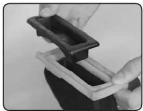
natural_image
Close-up of hands holding a black plastic tray with a white base, no visible text or symbols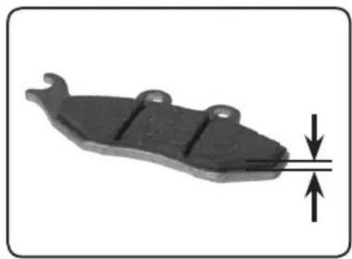
natural_image
Mechanical component with downward force arrow indicating compression or compression (no text or symbols)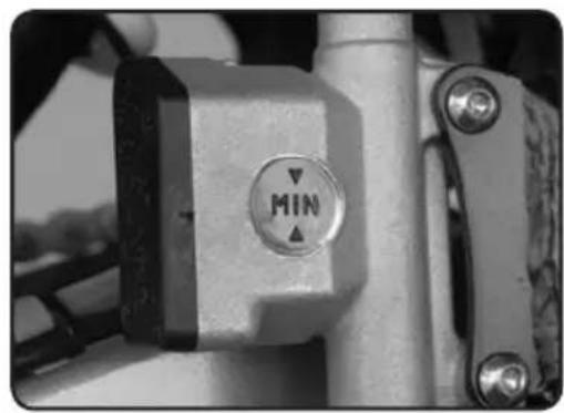
natural_image
Close-up of a mechanical lever with a circular indicator labeled 'MIN' (no additional text or symbols visible)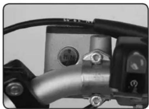
natural_image
Close-up of a mechanical component with metallic parts and wiring (no visible text or symbols)Filtre à air
natural_image
Mechanical device with labeled parts (1 and 2), no visible text or symbols beyond labelsnatural_image
Close-up of mechanical components with numbered annotations (1 and 2) pointing to specific parts, no readable text or symbols beyond labels.natural_image
Close-up of a bicycle brake lever with labeled parts (1 and 2), showing handle, grip, and lever mechanism (no text or symbols beyond labels)natural_image
Close-up of a mechanical component with a black central pin and flanged ends, no visible text or symbols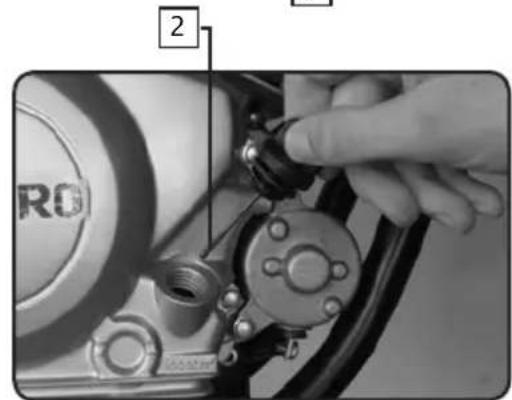

natural_image
Close-up of a mechanical pipe fitting with a numbered component (3) and no visible text or symbols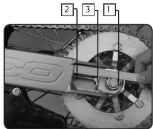
natural_image
Close-up of a car tire pressure gauge with hoses and dials (no visible text or symbols)
natural_image
Close-up of a hand using a tool to cut or repair a damaged metal surface, no visible text or symbolsPneumatiques
Congratulations! You are now the owner of a Sherco 125 4 Stroke Motorcycle. You will enjoy many miles of riding pleasure if you follow he instructions in this manual.
This manual explains the function, inspection, basic maintenance and tuning of your new Sherco Motorcycle. Do not hesitate to contact your local Sherco Dealer if you have any questions about these procedures.
We recommend that you read and understand everything in this manual before you ride your motorcycle.
In order to keep your new Sherco Motorcycle operating properly it is necessary that you follow the maintenance procedures outlined in this manual.
The motorcycle shown in the pictures might be slightly different from the one that you have purchased, however the procedures described are accurate
SOMMARY
Identification numbers .....p33
Technical data....P34
Vehicle identification .P35
Vehicle description ..... P36
Controls . . . . . . . . . . . . . . . . . . . . . . . . . . . . . . . . . . . . . . . . . . . . . . . . . . . . . . . . . . . . . . P37
Initial operations . . . . . . . . . . . . . . . . . . . . . . . . . . . . . . . . . . . . . . . . . . . . . . . . . . . . . . . . . . . P38
Security rules . . . . . . . . . . . . . . . . . . . . . . . . . . . . . . . . . . . . . . . . . . . . . . . . . . . . . . . . . . . . . . . P39
Dashboard functions....p40
Riding your motorcycle . . . . . . . . . . . . . . . . . . . . . . . . . . . . . . . . . . . . . . . . . . . . . . . . . . . . . . . . . P50
Maintenance and setting P51
Cleaning and storage .....P57
IDENTIFICATION NUMBERS
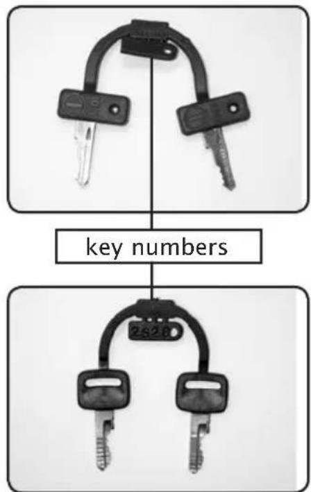
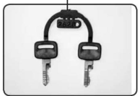
Record in the spaces below, the ignition key number, the steering lock number and the vehicle serial number of your motorcycle.
Ignition key number (see the picture)
Steering lock key number (see the picture)
Engine serial number (see page 35)
TECHNICAL DATA
PERFORMANCE
Maximum power : 8,0 kW at 8000 rpm
Maximum Torque : 10,41 Nm at 6500 rpm
DIMENSION
| Overall length : TT : 2110 mm SM : 2060 mm | ||||
| Overall width | : | 830 | mm | |
| Height : TT : 1220 mm SM: 1190 mm | ||||
| Wheel base | : | 1450 | mm | |
| Basic weight | : | 111 | kg | |
ENGINE
Type : 4 stroke, single cylinder, air cooled Displacement : 123,7 cc
Bore X stroke : 54 mm X 54 mm
Compression ratio : 10 : 1
Ignition system : Electronic CDI
Spark plugs : NGK CR6HSA / U22 FSR-U/N-Denso
Gear box oil : 1 liter, SAE 10W50
TRANSMISSION
Type : 5 speed Clutch : wet multidisc
Transmission system : chain drive
Primary reduction ratio : 3,58 (68/19)
Secondary reduction ratio : 3,14 (44/24)
Gear ratio : 1 st 2,64 (37/14)
: nd 1,28 (32/18)
: rd 1,32 (25/19)
: th 1,05 (23/22)
: th 0,88 (21/24)
FRAME
Tire brand : VEE RUBBER - MICHELIN
Size
Front : TT : 3.00-
Rear : TT : 4.10-1
Fuel tank capacity : 7,5 l 87/93 octane unleaded gasoline
ELECTRICAL EQUIPEMENT
Headlight : 12 V 35/35 W
Tail/brake light : 12 V 21/5 W
Flasher light : 12 V 10
TT : Enduro model
SM : Supermotard model
Technical data is subject to change without prior notice.
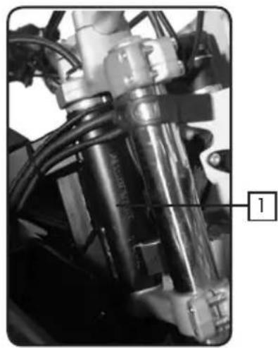
VEHICLE IDENTIFICATION
natural_image
Close-up of a mechanical assembly with visible components and wiring (no text or symbols)Véhicule serial number
- The serial number of the vehicle is recorded on the right side of the steering tube.
natural_image
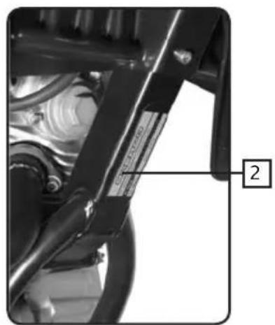
Close-up of a mechanical assembly with visible components and a numbered label (2), no readable text or symbols present.- The identification plate is attached under the frame.
This plate indicates the emissions control number of the vehicle and the noise level in dba at a given RPM.
The identification plate also includes the machine serial number.
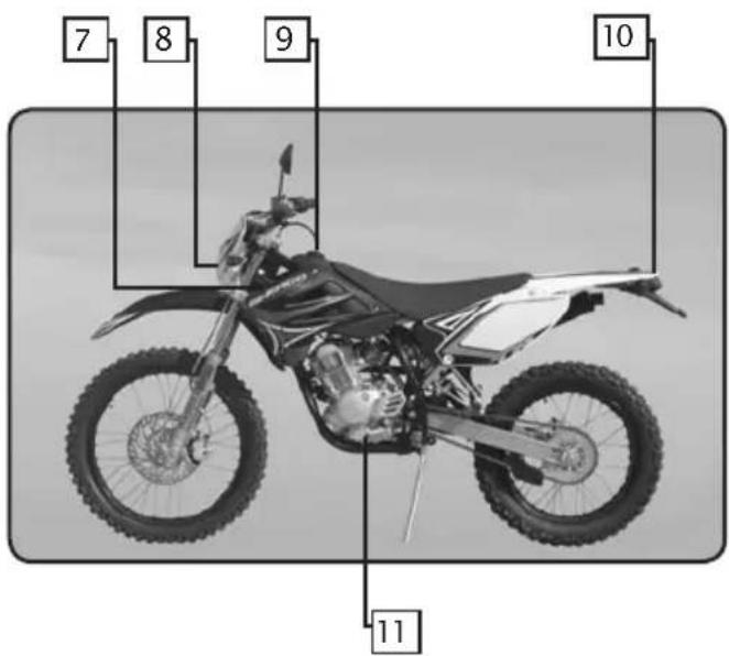
VEHICLE DESCRIPTION
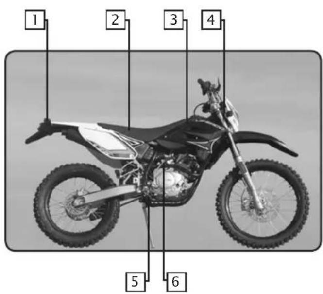
- Rear turn signal lights
- Seat
- Fuel tank
- Front turn signal lights
- Rear brake pedal
- Kick starter lever
- Steering lock
- Headlight
- Fuel tank cap
-
Tail light/brake light/ licence plate light
-
Gearshift lever
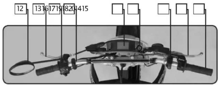
- Left hand rear-view mirror
- Clutch lever
- Left handlebar control switch
- Speeddometer panel
- Dashboard
- Main electrical shift
- Right handlebar control switch
- Front brake lever
- Accelerator grip
CONTROLS
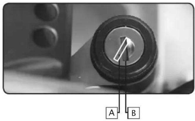
natural_image
Close-up of a mechanical knob with labeled points A and B, showing a dial indicator (no text or symbols beyond labels)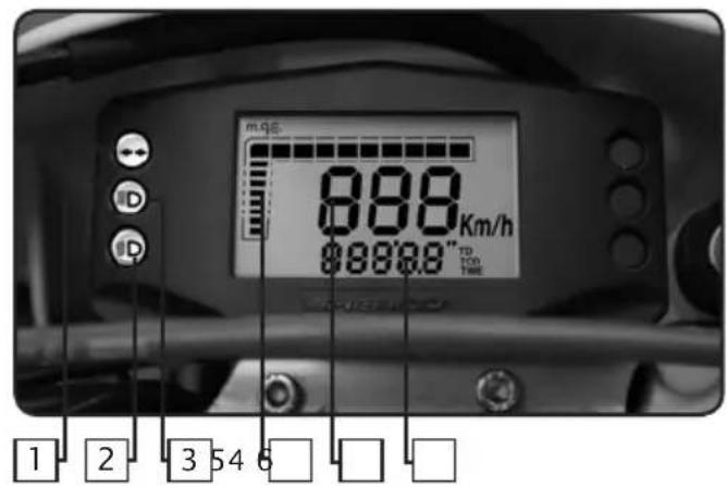
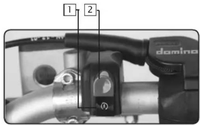
Main electrical switch
The switch has 2 positions:
A. the engine can be started.
B. engine is off and cannot be started.
Dashboard
- Turn signal indicator light: flashes when the turn signals flash.
- Headlight indicator light: illuminated when the headlight is in the low beam position.
- High beam indicator light.
- Rpm indicator
- Speedometer.
- Odometer in kilometers.
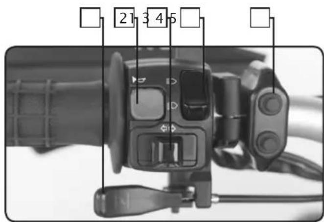
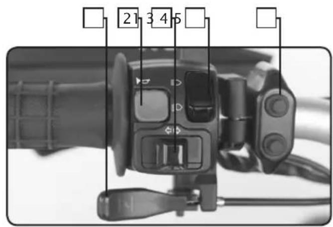
Left handlebar control switch
- Throttle control.
- Horn button.
- Turn signal switch.
- Light switch.
- Speedometer panel.
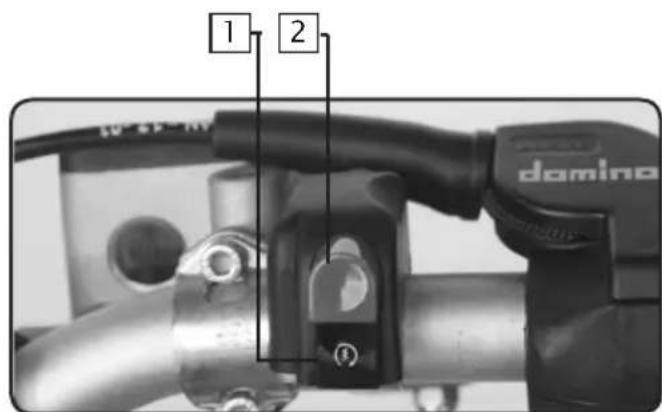
Right handlebar control switch
- Electric start button.
- Engine stop button.
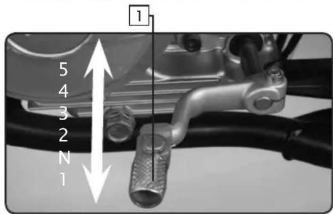
Gearshift lever
- The gear shift lever which is located on the left side of the engine is used to select the 5 gears in the transmission
natural_image
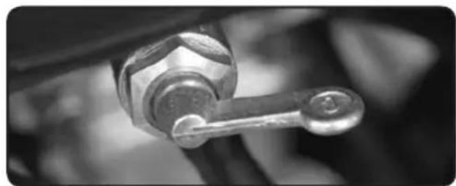
Close-up of a mechanical lever handle with a metallic knob (no text or symbols visible)3 positions fuel petcock
OFF: When the lever is in this position, fuel will not flow. Always return the lever to this position when the engine is not running.
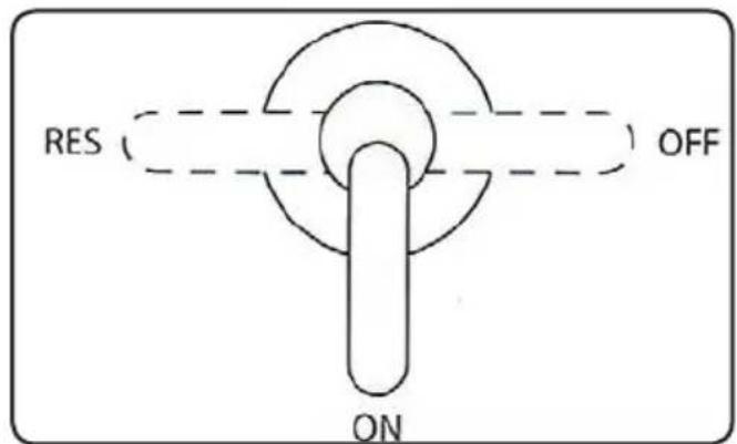
ON: With the lever in this position, fuel flows to the carburetor. Normal riding is done with the lever in this position.
RES: This is the reserve position. If you run out of fuel while riding, move the lever to this position.
INITIAL OPERATION
The break in period if 500 km. During this period it is mandatory that you follow the procedures described below.
If these procedures are not followed the life of your motorcycle may be drastically reduced.
- Do not accelerate or race the engine immediately after starting. Let the engine idle for a few minutes in order for it to warm up.
- Do not run at full load during the break in period.
- In order to validate the manufacturers warranty, you must return your Sherco motorcycle to your authorized Sherco dealer at the end of the 500 km break in period.
SAFETY
- We recommend that you always wear an approved helmet when you ride your motorcycle.
- For optimum safety and reliability you have to keep your motorcycle in good repair with a rigorous maintenance schedule.
- Gasoline is inflammable, fill the fuel tank when the engine is not running.
- Exhaust gases are toxic, do not run the engine in a closed space.
- Always park the motorcycle on a flat hard surface. Do not park the motorcycle on a soft surface or on a slope. Check the stability before leaving your motorcycle.
-
You should inspect the following items daily, before you ride your motorcycle.
-
Tires
- Engine oil
- Fuel
- secondary drive chain
- Steering
-
Brakes
-
Throttle control
- Clutch
- Sidestand
- Electrical system
- Fasteners (bolts, nuts, screws)
: Check for wear and pressure
: Level. (see the maintenance and adjustment chapter)
: Make sure there are no leaks
: Tightness. (see the maintenance and adjustmentchapter)
: Make sure that it turns freely
: Check for proper operation, make sure that there is plenty of brake fluid and that the pads are serviceable.
(see the maintenance and adjustment chapter)
: Check for proper operation, the throttle should turn freely and not stick. (see the maintenance and adjustment chapter)
: Check for proper operation. (see the maintenance and adjustment chapter)
: Check the operation of the safety switch, the engine should not start when the sidestand is down and should run when it is up
: Check the operation of the horn, the lights and the starting system.
: Inspect all bolts, nuts and screws, make sure they are properly tightened.
If during this inspection you find a defect, refer to the Maintenance and Adjustment chapter maintenance and adjustment, or contact your authorized SHERCO dealer
DASHBOARD
1.0 DÉFINITION OF COMPONENTS
1.1 LCD Ccrystal
1.2 Pulsator
2.0 FUNCTIONS AND FEATURES
2.1 Current speed function
2.2 Total distance Function (TOD)
2.3 Clock functions (TIME)
2.4 Automatic trip function (TD)
2.5 Automatic trip function (CountDown)
2.6 Automatic chronometer function (LAP)
2.7 Modification to wheel circumference, units of measurement and wheel impulses
2.8 Succession of functions shown
2.9 Button function
2.10 Initial installation of instrument
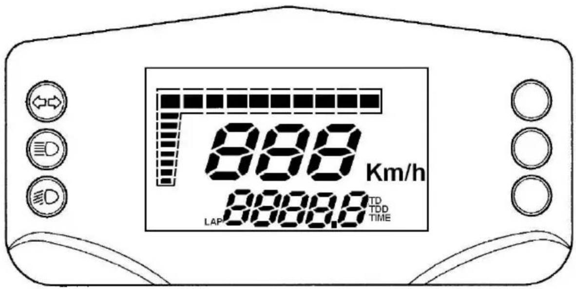
1.0 DEFINITION OF COMPONENTS
The unit comprises:
A digital LCD display
Three LED indicators
A separate control pulsator is also required.
Backlighting is effected using red LEDs.
1.1 LCD (liquid crystal display)
1.2 Pulsator
The impluse swith is on the left side of the handle-bar near the combination swith.
2.0 FUNCTIONS AND FEATURES
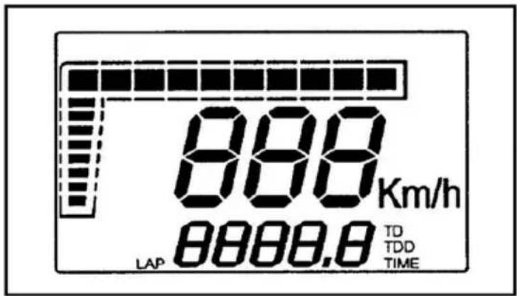
2.1 Current speed (speedometer) function
This function describes the function/display of current speed. The information is always displayed on the 6-8 digits, accompanied by an indication through the use of the graphic bar (Fig. 2); if the measurement unit selected is k.p.h. (default value), the relative digit is displayed; by pressing the button and gaining access to the Set-Up menu, it is possible to select m.p.h.; in this case, the speed indication will not be accompanied by any text showing the unit of measurement selected.
2.2 Total distance function (TOD)
This function describes the function/display of the total distance traveled. The information is displayed on the 1-5 digits accompanied by the letters TOD, as shown in figure 2; depending on the unit of measurement selected, the figure is shown in kilometres (default value) or miles. In normal conditions of use of the instrument, it is not possible to zero this information. The maximum figure that can be displayed is 99,999 km. (or miles); once this is exceeded, the counter is reset to zero. The figure shown increases by integer values of 1 km./mile.
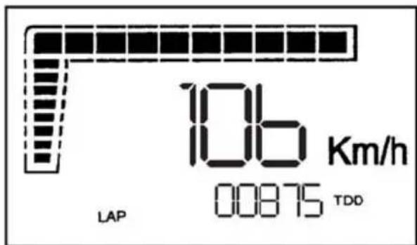
fig.2 TOD function
2.3 Clock function (TIME)
This function describes the correct operation/display of the clock function. This function is always displayed in an hh:mm format, using digits 1-5, as shown in Fig.3. The time may be adjusted only when stationary by pressing the button (under the TIME function) until only the segments relative to the clock function and the letters TIME are active, while all the other segments are switched off (Fig.4).
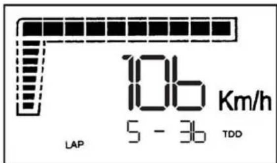
fig.3 TIME function
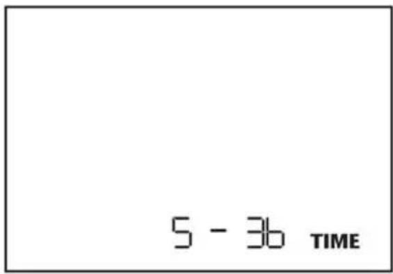
fig.4 TIME Adjustment
It is possible to adjust first the hours and then the minutes, depending on the digit selected (which will be shown flashing with f=1Hz, Duty=50%); briefly pressing the button will increase the parameter selected by one, while longer pressure will enable another parameter to be selected (minutes rather than hours). Once the adjustment has been effected, normal operation is resumed by holding the button depressed for about 3 seconds. The Time parameter will be visualised in a 24h format if the unit of measurement selected is k.p.h., and in the 12h format if the unit of measurement selected is m.p.h.
Note 1 Once into the adjustment menu, the system will return to normal operation mode if 20 seconds pass without the button being pressed.
Note 2 Once into the adjustment menu, if the bike starts to move (speed>0), the system will automatically return to normal operation mode.
Sequence displayed: from 0:00 to 23:59 in 0-24h format
from 0:00 to 12:59 in 0-12h a.m. format
from 1:00 to 11:59 in 0-12h p.m. format
Precision of the clock: ±2.5"/day. The information is not saved to memory.
2.4 Automatic trip function (TD)
This function describes the function/display of the unit's automatic trip function. This function is always shown using the 2-5 digits and is accompanied by the letters TD, as shown in Fig.5; the figure shown represents the distance run by the bike expressed in kilometres or miles (depending on the unit of measurement selected), with a resolution of 0.1 (kilometres or miles); this counter is automatic: it is activated by the first impulse from the speed sensor. The figure is not saved permanently. It is possible to zero the counter associated with this parameter by pressing the button (below the TD function) for about 3 seconds until the value 000.0 appears. The zeroing of the TD can be effected both while stationary and whilst moving, and also zeroes the LAP function. If the figure exceeds 999.9, the system will automatically zero the TD and LAP, and will then restart the trip.
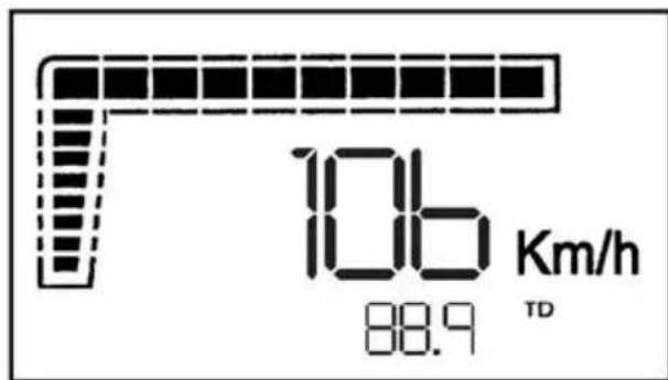
fig.5 TD function
2.5 Automatic trip function (CountDown)
This function describes the function/display of the unit's countdown trip function. This function is always shown using the 2-5 digits and is accompanied by the flashing letters TD (see Fig.6); the counter is always active and counts down with a resolution of 0.1 (kilometres or miles depending on the unit of measurement selected). It is possible to modify the value associated with this parameter by pressing the button (below the TD function and whilst stationary) for about 3 seconds until only the segments relative to the countdown function and the letters TD (still flashing) are active, while all the other segments are switched off, as shown in Fig.7.
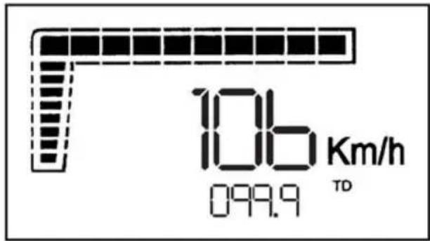
fig.6 CountDown function
It is possible to modify the different figures in the counter, starting with the largest figure and moving successively to the lesser one; depending on the data selected (shown flashing with f=1Hz, Duty=50%), a brief pressure on the button will decrease the figure by one, while a longer pressure will enable the selection of a different parameter. Once the adjustment has been finished, normal operation mode is activated by pressing the button for about 3 seconds while the lesser figure is selected. If the figure counts down to 000.0, the system will Re-initialize the value at 999.9.
Note 1 Once into the adjustment menu, the system will return to normal operation mode if 20 seconds pass without the button being pressed.
Note 2 Once into the adjustment menu, if the bike starts to move (speed>0), the system will automatically return to normal operation mode.
Sequence displayed: from 999.9 to 000.0
The information is not saved to memory
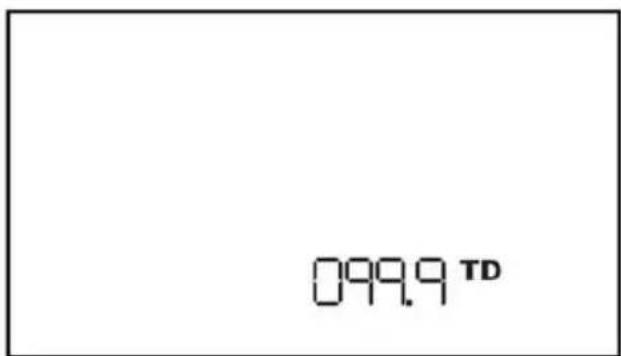
fig.7 CountDown adjustment
2.6 Automatic chronometer function (LAP)
This function describes the function/display of the chronometer associated with the TD. The information is displayed on digits 1-5 and accompanied by the letters LAP, as shown in Fig.8. The figure displays the time lapse of the bike (in mm:ss format if hours = 0, and in hh:mm format if hours > 0), associated with the TD parameter; it is therefore an automatic counter: it is automatically activated with the first impulse from the speed sensor (when LAP is operative, the digit separating hours and minutes, and minutes and seconds, flashes, and is displayed fixed when LAP is not operative), and stops 3 seconds after reception of the last impulse sent by the speed sensor. The data is not saved permanently to memory. It is possible to zero the counter associated with this parameter by pressing the button (below the LAP function) for about 3 seconds until the value 00'00" appears. The zeroing of the LAP can be effected both while stationary and whilst moving, and also zeroes the TD function. If the figure exceeds 23-59 (that is 23 hours 59 minutes and 59 seconds), the system will automatically zero the LAP and TD, and will then restart the trip function.
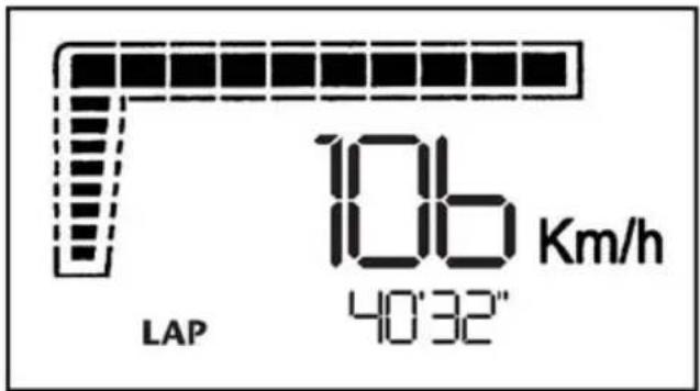
fig.8 LAP function
2.7 Modification to wheel circumference, units of measurement and wheel impulses
The modification to the wheel circumference, units of measurement and number of wheel impulses can only be effected while stationary, maintaining the button pressed under the TOD function until the only information displayed (in the 2-5 digits) is the wheel circumference and all the other segments are off (see Fig.9). It is possible to modify the various figures constituting the value for the wheel circumference, starting with the largest figure and moving successively to the lesser one; depending on the digit selected (shown flashing with f=1Hz, Duty=50%), a brief pressure on the button will increase the figure by one, whilst a longer pressure will enable the selection of a different figure
Note 1 Adjustment interval (wheel circumference): from 1,000mm to 2,500mm with steps of 1mm.
Note 2 If the wheel circumference selected is >2,500mm, the system will automatically set the default value (2,091mm).
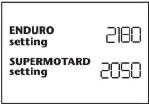
Fig.9 Adjustment of wheel circumference
Once the wheel circumference has been adjusted, it is possible to modify the unit of measurement by holding the button depressed for about 3 seconds while the lesser figure is selected; at this point, the display will show the letters ‘km/h’ and ‘Mph’, with the unit selected initially shown flashing (f=1Hz, Duty=50%). This parameter is modified in the same way as described above. The change in unit of measurement will irreversibly cancel the TD and LAP
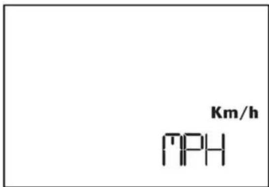
Fig.10 Adjustment of units of measurement
By holding the button depressed for about 3 seconds while the unit of measurement is selected (shown flashing with f=1Hz, Duty=50%), it is possible to modify the number of wheel impulses. This parameter expresses the number of impulses the electronic sensor sends to the instrument for each complete turn of the wheel. The adjustment interval permitted ranges from a minimum of 1 for each complete turn of the wheel to a maximum of 6.
Note 3 The impulses may also NOT have equal lapses of time between them.
By holding the button depressed for about 3 seconds while the value is selected, it is possible to return to standard operating mode
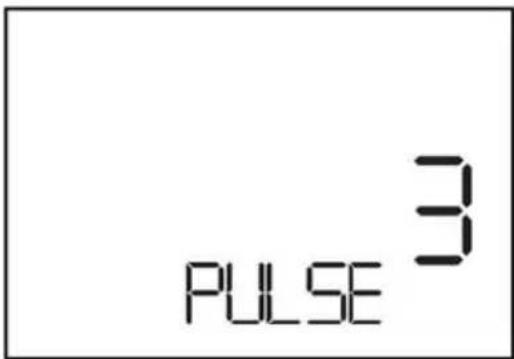
Fig.11 Adjustment of impulses for each complete turn of the wheel
Note 4 The information concerning the values for the wheel circumference, unit of measurement and number of impulses for each turn of the wheel selected, are saved to memory.
Note 5 Once into the adjustment menu, the system will return to normal operation mode if 20 seconds pass without the button being pressed.
Note 6 Once into the adjustment menu, if the bike starts to move(speed>0), the system will automatically return to normal operation mode.
22.8 Succession of functions shown
Scrolling through the functions is always possible, whether stationary or moving, by pressing on the button in accordance with the sequence shown below

flowchart
graph LR
    A["→"] --> B["TIMELAPTODTDCOUNTDOWN"]
    B --> C["→"]
2.9 Button function
The function of the button varies depending on the function displayed, as shown in the table below.
| Fonction MODE | |
| TIME | If T≥3” and Speed = 0, the time-setting function is activatedIf T<3” or Speed>0, the functions may be scrolled through |
| LAP | If T≥3” LAP and TD are resetIf T<3” the functions may be scrolled through |
| TOD | If T≥3” and Speed>0, the circumference, unit of measurement and number of impulses per turn of the wheel function is activatedIf T<3” or Speed>0, the functions may be scrolled through |
| TD | If T≥3” LAP and TD are resetIf T<3” the functions may be scrolled through |
| If T≥3” and Speed>0, the countdown setting function is activatedIf T<3” or Speed>0, the functions may be scrolled through | |
2.10 Initial installation of instrument
The default value of the wheel circumference is 2,091mm, and the unit of measurement is k.p.h. for the speed and kilometres for distance; again by default, the system is set to receive 1 impulse for each complete turn of the wheel. To modify any of these parameters, it is necessary to proceed as per the instructions above. During the initial installation of the instrument, the display will Visualize the version and date of the software installed for about 2 seconds. Immediately after the display's Check, and the visualisation of the pre-set wheel circumference and number of impulses for each turn of the wheel, the system activates the standard operating mode.
Starting a cold engine:
- Turn the fuel petcock to the ON position.
- Set the sidestand up (the sidestand is equipped with a witch which prevents the engine from starting when it is down)
- Turn the ignition key to the on position, first position to the right. (clockwise)
-
Using the gearshift lever, place the transmission in neutral.
-
Engage the choke and slightly open the throttle.
-
To start the motor push the engine start button, once the engine is started remove your finger from the button.
The engine may also be started by using the kick starter lever. Follow the same process as above but instead of pushing the engine start button, unfold the kick starter lever and push down on it with your foot. Once the engine starts return the kickstarter lever to its original position.
- Allow the engine to warm up for several minutes in neutral before shifting into 1st gear and riding off.
Starting warm engine
Follow the above instructions but omit steps 5 and 7.
Accelerate the engine slightly after it starts.
Shifting gears
The gear shift lever positions are shown on page 35. To find neutral, push down on the pedal until it is in first gear (you will feel a resistance to further movement). Lift up slightly on the pedal.
- Close the throttle and pull in the clutch lever.
- Step on the gear shift lever and place the transmission into first gear.
- Smoothly open the throttle and slowly release the clutch lever.
Once you have reached the proper speed, shift into the next higher gear
Stopping
Using the ignition key stop the engine, remove the key from the main switch and place the petcock in the off position.
You must know these functions completely prior to operating your motorcycle for the first time.
MAINTENANCE AND SETTING
| OPERATION | FREQUENCY (the first of either) | See page | ||||||||
| EVERY | DISTANCE (In km) | |||||||||
| 1000 | 6000 | 12000 | 18000 | 24000 | 30000 | 35000 | ||||
| Idle speed | C | - | E | E | E | E | 51 | |||
| Throttle handle play | S - C - O - A | - | E | E | E | E | - | |||
| Spark plug gap | N - C - O - A | - | EEE | E | E | E | 51 | |||
| Air filter | N - - | E | O | O | O | O | 52 | |||
| Brake pad and disc wear | C | - | EEE | E | E | E | E | 52 | ||
| Brake fluid level | - C | EEE | E | E | E | 53 | ||||
| Brake fluid | 2 years | O | O | 53 | ||||||
| Front brake, Back brake | C | - | EEE | E | E | E | 53 | |||
| CLutch Lever play | - A | EEE | E | E | E | 53 | ||||
| Clutch | C ou | - O | O | O | O | - | ||||
| Engine Oil | S | - | O O | O | O | O | O | O | O | 54 |
| Oil filter | - | O | O | O | O | - | ||||
| Transmission chain | L - O - A | 1000 km | 54 | |||||||
| Transmission chain movement | C - O - A | 1000 km | 54 | |||||||
| Tire wear | C | - | EEE | E | E | E | 55 | |||
| Steering | S | - O | -EEE | A | E | E | E | - | ||
| Tightness of wheel spokes and discs | S - O - A | - | EEE | E | E | E | - | |||
| Tightness of nuts, bolts, joints | C - O - A | - | EEE | E | E | E | - | |||
| General lubrification | - | EEE | E | E | E | - | ||||
| Front fork oil | S - O | - | E | E | E | E | - | |||
| Swing arm pivot | S - O - L - A | - | E | E | E | - | ||||
| Lubricate steering bearings | S - O - L - A | - | E | E | E | - | ||||
| Master cylinders | S | 2 years | O | E | - | |||||
| Callipers | S | 2 years | E | - | ||||||
| Brake hose | S - O - C | 2 years | E | E | - | |||||
| Fuel inlet tube | S - O - C | 2 years | E | E | - | |||||
| Valve clearance | S | 2 years | A EE | E | E | - | ||||
| Oil strainer | N | E | E | E | E | - | ||||
Légendes: Inspection C - Setting A - Replace O - Obligatory Opération E - Contact a Sherco dealer S - Clean N - Lubricate L
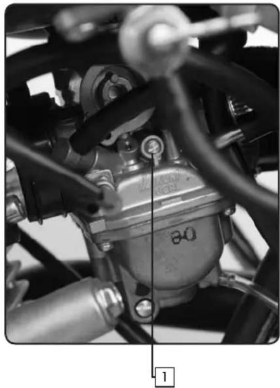
Engine IDLE speed
natural_image
Close-up of a mechanical assembly with hoses and a central component (no visible text or symbols)-
Start the engine and let it warm up for a few minutes.
-
Adjust the idle speed by turning the adjustment screw
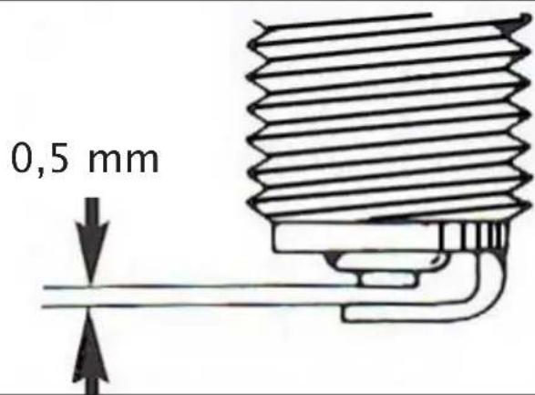
Spark plugs
| standard spark plugs | NGK CR6HSADenso U22 FSR-U/N | |
| Torque | 20-25Nm | |
| electrode gap | ||
 | ||
natural_image
Interior view of a mechanical or electronic device with multiple compartments and a handle (no visible text or symbols)
natural_image
Close-up of hands holding a black plastic tray with a white base (no text or symbols visible)
natural_image
Mechanical component with downward force arrow indicating compression (no text or symbols)
natural_image
Close-up of a mechanical lever with a circular indicator labeled 'MIN' (no additional text or symbols visible)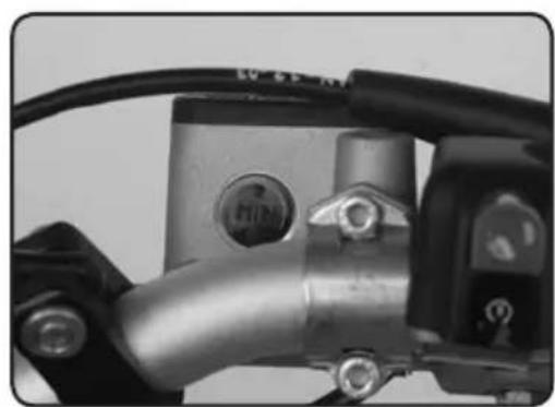
natural_image
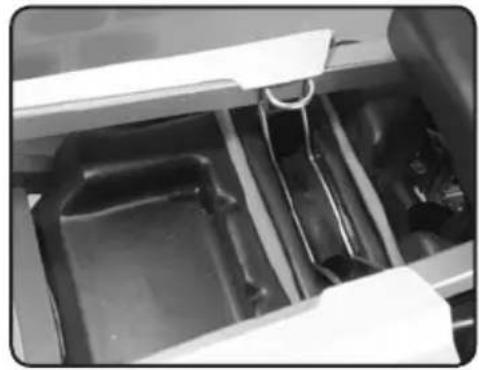
Close-up of a mechanical component with metallic parts and wiring (no visible text or symbols)Air filter
- Remove the seat.
- Remove the air filter cover (1).
- Remove the air filter (2).
- Clean the element with soap and water, squeeze the element to remove any excess water. Allow to dry completely.
- Impregnate the element with specialair filter product.
- Reinstall the air filter element.
- Reinstall the cover, making sure that it makes good contact with the airbox.
8 Reinstall the seat.
Brake pad wear
Remove both pads, if one or both pads measure less than 1mm they should be replaced.
Brake fluid level
If the brake fluid level is below the minimum level, add DOT 4 brake fluid to the maximum mark.
Always use the same type of brake fluid.
natural_image
Mechanical device with labeled parts (1 and 2), no visible text or symbols beyond labelsFront brake adjustment
- Loosen the lock nut (1).
- Turn the adjuster (2) until you obtain a 10 mm (approx.) clearan ce between the brake lever and the handlebar grip.
- Tighten the lock nut (1).
natural_image
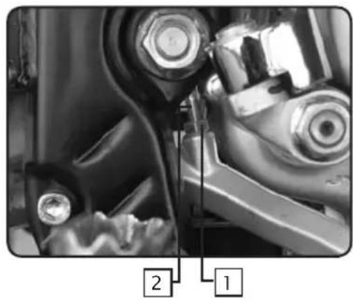
Close-up of mechanical components with numbered annotations (1 and 2) pointing to specific parts, no readable text or symbols beyond labels.Rear brake adjustment
The top of the brake pedal should be approx. 15 mm belos the top of the foot peg.
- Loosen the lock nut (1).
- Turn the adjuster (2) until you obtain the 15 mm dimension. Apply pressure to the brake pedal when you have the correct dimension.
- Tighten the lock nut (1).
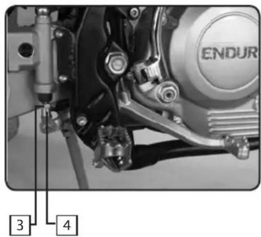
The rear brake pedal should have a clearance of approx. 3 mm with the stop screw.
- Loosen the lock nut (3).
- Turn the adjuster (4) until you obtain the 3 mm dimension.
- Tighten the lock nut (3).
natural_image
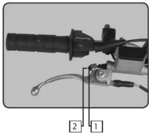
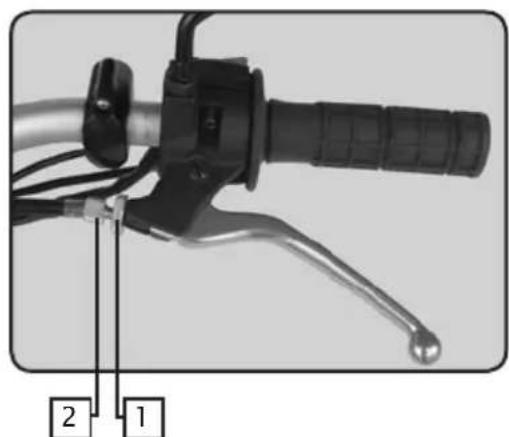
Close-up of a bicycle brake lever with labeled parts (1 and 2), showing handle, grip, and lever mechanism (no text or symbols beyond labels)Clutch lever adjustment
There are two places to adjust the clutch cable: one is on the lever and the other is on the cable near the engine. This illustration shows the clutch lever adjustment.
- Loosen the lock nut (1).
- Adjust the adjuster (2) until you obtain a free play of approx. 10 to 15 mm.
- Tighten the lock nut (1).
natural_image
Close-up of a mechanical component with a black central pin and flanged ends, no visible text or symbols
natural_image
Close-up of a hand adjusting a mechanical component with a labeled part (2), no visible text or symbols beyond the number and logo.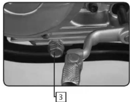
natural_image
Close-up of a mechanical pipe fitting with a numbered label pointing to a component (no readable text or symbols)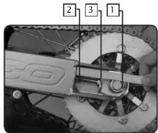
We recommend that you lubricate the chain with adapted chain lubricant
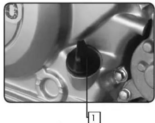
Engine Oil
Check the oil level (stop the engine and wait a few minutes)
- Stand the vehicle perpendicular to the ground.
- Remove the cap (1). If the level is between the two marks gauge, the level is correct.
- If the level is low, add the correct amount of the approved oil to bring it to the corect level.
- Replace the cap.
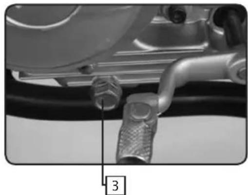
Oil change
- Warm up the engine and then shut it off.
- Place the vehicle over an approved receptacle.
- Remove the oil drain plug (3).
Note: the picture does not look like the drain plug. - Once the oil has completely drained, replace the drain plug (3) and torque it to 18 Nm.
- Remove the cap (2) and fill the engine with the approved amount.
Drive chain adjustment
- To check the drive chain for slack:
- The wheels have to be on the ground.
- The motorcycle has to be vertical.
- No one can be on the motorcycle.
-
If the vertical deflection is between 25 and 40 mm the chain must be adjusted.
-
Loosen the rear wheel axle nut (1).
- Adjust the deflection with the nuts adjusters systems (2) and (3) on both sides of the motorcycle until the chain deflection is between 12 and 24 ~mm . Make sure that the adjusters are in the same position on both sides.
- Tighten the rear wheel axle nut (1) to 90 Nm.
natural_image
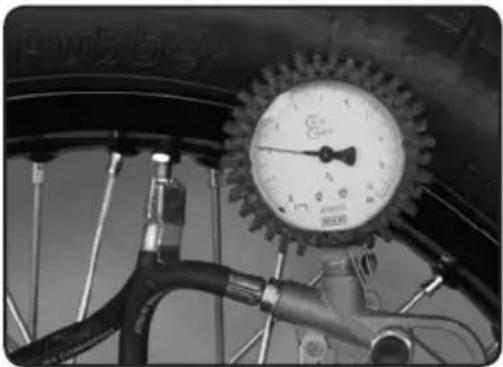
Close-up of a car tire pressure gauge with hoses and a valve (no visible text or symbols)Tires
- Tire pressure:
- Check the tire pressure on a regular basis with an accurate tire pressure gauge.
- The tire pressure must comply with the chart shown below.

natural_image
Close-up of a hand using a tool to trim or cut a car tire (no visible text or symbols)- Tire wear and damage:
- Check the tread depth on a regular basis with a tread depth gauge.
- If the tread depth is less than 2 mm it is mandatory that the tire be replaced.
- Check the tires to make sure that they do not have any cuts or bulges.
- If there is a lot of damage to the tires it is mandatory that you replace them.
| Maximum Load | 180kg | |||
| Max load(Total weight of lugages,passenger and pilot) | 165kg | |||
| Pressure(cold condition) | ENDURO | SUPERMOTARD | ||
| Front | Rear Front | Rear | ||
| Until 90kg | 130kPa(1,3 kg/cm2) | 150kPa(1,5 kg/cm2) | 180kPa(1,8 kg/cm2) | 200kPa(2,0 kg/cm2) |
| Between 90kgand max load | 150kPa(1,5 kg/cm2) | 180kPa(1,8 kg/cm2) | 200kPa(2,0 kg/cm2) | 220kPa(2,2 kg/cm2) |
Suspensions
Forks:
Paioli
∅41mm
Capacity per leg: 435cc 200mm air vol.
Viscosity:
SAE
7.5
CLEANING AND STORAGE
SHERCO recommends that you clean your new SHERCO 125 on a regular basis in order to maintain its appearance and prolong its life.
- Cover the exhaust outlet and the air filter intake with an appropriate cover. (a piece of plastic with a rubber band will work)
- To clean the engine, apply a good quality degreaser, scrub with a brush and then rinse the engine with a water hose.
- Wash the motorcycle first with a garden hose.
4 Wash the rest of the vehicle with hot soapy water. - Rinse with water.
- Dry with a chamois or a clean lint free cloth.
- Dry the chain and lubricate it with special adapted chain lubricant.
- Once you are finished cleaning the bike remove the covers from the intake and the exhaust. Start the engine and let it idle a few minutes.
Avoid the use of high pressure washers, the water can enter the bearings, the steering housing, etc. and cause severe damage.
Use a detergent specifically designed to wash automobiles or motorcycles, this will eliminate the possibility of damage to the tires.
Before storing the vehicle for a prolonged period (more than two months), it is recommended that you follow these instructions:
- Wash the motorcycle as described above.
- Drain the fuel tank and the carburetor.
- Remove the spark plug and place some drops of engine oil in the cylinder. Replace the spark plug and turn the engine over several times with the kick starter with the ignition switch in the off position, this will cover the internal surfaces of the cylinder with oil.
- Lubricate all of the pivot points and cables with spray protector
- Lift the motorcycle in order that the wheels leave the ground.
- Cover the exhaust exit with a piece of plastic to keep moisture from entering the engine.
- Place a thin coating of engine oil on all non painted metallic surfaces.
- Cover the motorcycle with an appropriate cover.
SHERCO
Motorcycles
ESPAÑOL
P.59

P.85
INTRODUCCIÓN
SHERCO
natural_image
Close-up of a black automotive key with two metallic keys attached, no text or symbols visible.Numéros de clés
natural_image
Black-and-white photo of a double key with two handles and a curved handle (no text or symbols visible)CARACTERÍSTICAS
PRESTACIONES
natural_image
Close-up of a mechanical knob with labeled points A and B, showing a dial indicator (no text or symbols beyond labels)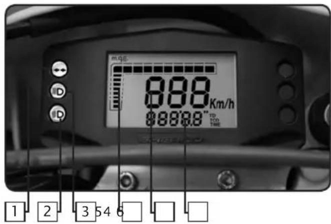


natural_image
Close-up of a mechanical lever handle with a hexagonal nut and lever mechanism (no text or symbols visible)Fig.8 Función LAP
natural_image
Close-up of an automotive engine component with visible hoses and calipers (no text or symbols)natural_image
Interior view of a kitchen drawer with plastic compartments and a white rack (no visible text or symbols)
natural_image
Close-up of hands holding a black plastic tray with a white base, no visible text or symbols
natural_image
Mechanical component with downward force arrow indicating compression or compression (no text or symbols)
natural_image
Close-up of a mechanical component with a circular button labeled 'MIN' and directional arrows (no readable text beyond the label)
natural_image
Close-up of a mechanical component with metallic body and bolts, no visible text or symbolsFiltro de aire
natural_image
Mechanical device with labeled parts (1 and 2), no visible text or symbols beyond labelsnatural_image
Close-up of a bicycle brake lever with labeled parts (1 and 2), showing handle, grip, and lever mechanism (no text or symbols beyond labels)natural_image
Close-up of a mechanical component with a black knob and metallic parts (no visible text or symbols)
natural_image
Close-up of a mechanical pipe fitting with a numbered label pointing to a component (no readable text or symbols)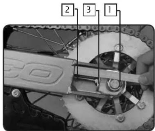
natural_image
Close-up of a car tire head with a pressure gauge and hoses (no visible text or symbols)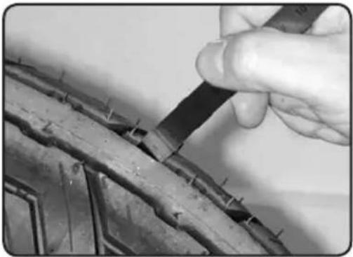
natural_image
Close-up of a hand using a tool to trim or cut a car tire (no visible text or symbols)Neumáticos
CONDITIONS DE LA GARANTIE SHERCO
- This manual has to be presented to the SHERCO vendor who is the sole enable to apply any overhaul operation or to answer to any application for warranty.
The overhauls and oil changes are mandatory to keep the right to warranty. Don't forget to note each of it.
- You have not to modify your SHERCO. It is homologated with respect of precise conditions, according with official rules of "code de la Route". Any modification applied to your SHERCO will immediately cancel the warranty.
- Please you have to read attentively the SHERCO warranty conditions and also the using advices here after described.
SHERCO WARRANTY CONDITIONS
Any new SHERCO motorcycle which is delivered with this present manual:
- Is covered by legal warranty of hidden defects, in agreement with present laws of each country.
- Is covered by a contractual warranty during 2 years without mileage limitation and parts.
Said warranty starts at the time of the first delivery to the final customer. This warranty can be applied by any vendor duly agreed by SHERCO.
This manual contains a first delivery card which has to be entirely filled up and returned to the SHERCO warranty desk by the SHERCO agreed vendor immediately after the first delivery to final customer. The owner signature prove the acceptance by owner of the present contract terms.
The SHERCO warranty is dedicated to the motorcycle. By this way any charge of property don't modify the warranty application. In order to have the benefit of said warranty the owner has to mandatory present the warranty manual and the warranty card duly filled up which the prove that the SHERCO overhaul operations has been completed in time, (with a allowance of plus or minus 60 miles (100 km) compared to the specified mileage).
The SHERCO warranty apply for free (labour and parts) connection of any defect concerning material or assembly, which appear after following conditions:
- All overhaul works have been achieved in the agreed SHERCO workshop vendor under responsibility of said vendor, the choice to change or prepare any part wich is admittedly defective is the sole SHERCO responsibility.
SHERCO warranty don't apply if it is proven that the defects are comming from:
- Motorcycle not normally maintained and non respect of instructions included in the SHERCO overhaul manual.
- Fitting on the motorcycles of parts, modifications or adaptations non permitted by SHERCO.
- Overhaul of the motorcycle made by another work shop than this agreed by SHERCO.
- Abnormal use of the motorcycle (for example: participation to sport races, overloads, motorcycle unutilised during a too long time)
- Normal wear of parts.
The parts with normal wear as: tyres, wiring, spark plugs, spark plug, cap, lights, chains, brackets, brakes pads and calipers exhaust pipes (by internal con) are not covered by the warranty; Also, engine blocking, holes on pistons, yellowing of chrome plating, due to bad adjustments, bad oil/ fuel mix or too low oil level are not covered by the warranty.
This contractual warranty don't apply for normal overhaul expenses, oil grease etc..., an also expenses related to emergency repairs, immobilisation of the motorcycle and removal expenses, damages of carried goods.
WARNING: The use of, silencer or air filter which are non original parts, or modified original parts in order to increase the level of noise cancels automatically any warranty application. In addition, said modifications which increase noise, power and speed are under total responsibility of the owner.
NOTA : In case of damage in a limitrophe country we are asking you to present the warranty claim to your vendor and to join the associated defective parts with corresponding invoices.
OBLIGATORY CONTROL CHECK LIST PRIOR TO DELIVERY BY THE DEALER
Visual control
. Paint
. Fairing fixation
. Scratches
. Cleanliness
O.K.
Tightness control
. Security tightness (wheel, handle bars)
O.K.
Electric circuits
. On / off circuit
. Headlights, indicators, parking lights and their corresponding dashboard lights
. Beam setting in line with legislation
. Rear light, parking light, stop light
. Front and rear stop contacts
. Indicators and their dashboard lights
. Side lights
. Dashboard instrument test
. Horn
. Starter
O.K.
Fluid circuits
. Hydraulic braking circuit fluid level
. Engine oil level in 4 stroke motors
O.K.
Road trial
. Cold start
. Dashboard instruments operational
. Throttle control response
. Stability upon acceleration and braking
. Effectiveness of front and rear brakes
. Effectiveness of front and rear suspension
. Unusual noises
O.K.
Static control after road trial
. Hot start
. Starter operational
. Idling (while turning the handle bars)
. Smooth steering rotation
. Leaks
O.K.
Running control
. Hydraulic braking circuit
. Mechanical braking circuit
. Clutch
. Four stroke motor
. Lever movement
. Brake actuating lever and/or pedal
. Throttle operational control
. Check paperwork
. Verification of chassis n° and engine n°
. Assembly of registration plate
. Check locks
. Check tyre pressure
. Assembly of rear view mirrors and any accessories
O.K.
Seller's stamp and signature
SHIET
RCCO
Motorcycles
| Scheduled service n°1: 1000km or 4 months - whichever is first Date: ......Dealer stamp: ...... | Vehicle N°Service date: ...... Chassis N°: ......Dealer stamp: ...... |
| Scheduled service n°2: 6000km or 4 months - whichever is first Date: ......Dealer stamp: ...... | Vehicle N°Service date: ...... Chassis N°: ......Dealer stamp: ...... |
| Scheduled service n°3: 12000km or 4 months - whichever is first Date: ......Dealer stamp: ...... | Vehicle N°Service date: ...... Chassis N°: ......Dealer stamp: ...... |
| Scheduled service n°4: 18000km or 4 months - whichever is first Date: ......Dealer stamp: ...... | Vehicle N°Service date: ...... Chassis N°: ......Dealer stamp: ...... |
| Scheduled service n°5: 24000km or 4 months - whichever is first Date: ......Dealer stamp: ...... | Vehicle N°Service date: ...... Chassis N°: ......Dealer stamp: ...... |
| Scheduled service n°6: 30000km or 4 months - whichever is first Date: ......Dealer stamp: ...... | Vehicle N°Service date: ...... Chassis N°: ......Dealer stamp: ...... |
| Scheduled service n°7: 36000km or 4 months - whichever is first Date: ......Dealer stamp: ...... | Vehicle N°Service date: ...... Chassis N°: ......Dealer stamp: ...... |
| Non-respect of the servicing schedules will lead to the automatic cancellation of the guarantee. Service and maintenance will be invoiced. In the event of applications under guarantee, the dealer's invoices and service stamps will be required. | |
IDENTITY SHEET
(Please complete all sections)
Use capital letters
Model name:
Type mine: ....
Chassis n°: ....
Model name: ....
Engine n°: ....
Owner:
Family name: ....
First name: ....
Address:
N°..... sreet.....
Post Code: ....Town:....
Tel: ...... Fax: ......
Duration of the guarantee: 24 months
Dealer stamp and signature
Code
Date: Signature:
GUARANTEE REGISTRATIONFORM
(Please complete all sections)
Use capital letters
Model name:
Type mine: ....
Chassis n°: ....
Model name: ....
Engine n°: ....
Owner:
Family name: ....
First name: ....
Address:
N°..... sreet.....
Post Code: ....Town:....
Tel: ...... Fax: ......
Duration of the guarantee: 24 months
Dealer stamp and signature
Code
Date: Signature:
If the control form is not duly stamped, the guarantee will be considered null and void.
SHIE
RCO
Motorcycles
Manual de garantía p98

p103
MANUAL DE GARANTÍA
The customer declare having read the warranty conditions and accept it totally and unreservedly.
*Card to be returned by the vendor immediately after delivery.
natural_image
Black and white banner with abstract background elements and a stylized 'SHEE' logo (no readable text or symbols)CHANGEMENT DE PROPRIÉTAIRE - NEW OWNER NUEVO PROPIETARIO
NB: In case of owner change, the hereunder card has to be filled up by the owner and sent to SHERCO within 15 days max after said owner change.
New owner signature for warranty terms agreement.
Please return this warranty from to your Sherco dealer.
Please return this warranty from to your Sherco dealer.