SCAN1100RGB - Lighting IBIZA SOUND - Free user manual and instructions
Find the device manual for free SCAN1100RGB IBIZA SOUND in PDF.
User questions about SCAN1100RGB IBIZA SOUND
0 question about this device. Answer the ones you know or ask your own.
Ask a new question about this device
Download the instructions for your Lighting in PDF format for free! Find your manual SCAN1100RGB - IBIZA SOUND and take your electronic device back in hand. On this page are published all the documents necessary for the use of your device. SCAN1100RGB by IBIZA SOUND.
USER MANUAL SCAN1100RGB IBIZA SOUND
natural_image
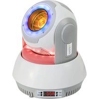
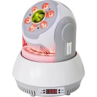
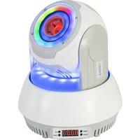
Black SCANTO laser projector with control panel and warning sign (no readable text or symbols on device body)MANUAL
FR - MANUEL D'UTILISATION - P. 8
This laser complies with the international standards EN60825-1:2014. It is meant exclusively for professional use.
Its installation and use should only be carried out by a skilled technician who is aware of the specific dangers of lasers.
REMINDER OF SAFETY INSTRUCTIONS
Lasers of class 3 and 4 are for outdoor use only.
Inside the public area, any laser shooting towards the audience is strictly forbidden except if a safety area of 5m radius is marked around the area to which the audience cannot get access.
The area called "public area" is defined by the space of 3m above the area occupied by the audience and a width of 2.5m around this area. The public area must be clearly identified by signs on the ground.
Inside the public area only a scanning movement is allowed within the terms and conditions defined by the international technical laser safety report.
The laser unit must be installed out of reach of the audience and at a minimum of 3m above the ground where the audience is present or protected by a safety perimeter of 5m radius.
The laser unit must be installed in such a way that it can't be moved under the effect of disruptions such as crowd movements, vibrations or gusts of wind.
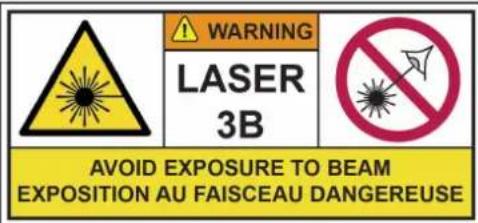
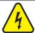
EXPLANATION OF SYMBOLS ON THE SILKSCREEN
The triangle containing a lightning symbol is used to indicate whenever your health is at risk (due to electrocution, for example).
An exclamation mark in a triangle indicates particular risks in handling or operating the appliance.
CE The unit complies with CE standards
For indoor use only
Minimum distance between the appliance and other objects
Don't stare into the beam

CAUTION DO NOT OPEN THE HOUSING SHOCK HAZARD
SAFETY INSTRUCTIONS
This unit contains high power laser devices internally. Do not open the laser housing, due to potential exposure to unsafe levels of laser radiation. The laser power levels accessible if the unit is opened, can cause instant blindness, skin burns and fi res.
- Please read these instructions carefully, they include important information about the installation, usage and maintenance of this product.
- Please keep this User Guide for future reference. If you sell the unit to another user, be sure that he also receives this instruction booklet.
• Always make sure that you are connecting to the proper voltage, and that the line voltage you are connecting to is not higher than that stated on the decal or rear panel of the fi xture.
• This product is intended for indoor use only!
• This unit must be earthed.
- To prevent risk of fire or shock, do not expose fixture to rain or moisture. Make sure there are no flammable materials close to the unit while operating.
- The unit must be installed in a location with adequate ventilation, at least 20in (50cm) from adjacent surfaces. Be sure that no ventilation slots are blocked.
• Always disconnect from power source before servicing or replacing fuse and be sure to replace with same fuse size and type.
- Secure fixture to fastening device using a safety chain.
• Maximum ambient temperature (Ta) is 104^ F ( 40^ C). Do not operate the fixture at temperatures higher than this. - In the event of a serious operating problem, stop using the unit immediately. Never try to repair the unit by yourself. Repairs carried out by unskilled people can lead to damage or malfunction. Please contact the nearest authorized technical assistance centre. Always use the same type of spare parts.
- Don't connect the device to a dimmer pack.
• Make sure the power cord is never crimped or damaged. - Never disconnect the power cord by pulling or tugging on the cord.
- Don't expose your eyes to the light source while it is on.
DISCONNECT DEVICE: Where the MAINS plug or an appliance coupler is used as the disconnect device, the disconnect device shall remain readily operable.
LASER EMISSION DATA
As measured under IEC measurement conditions for classification.
Laser Classification....Class 3B
Green Laser Medium....DPSS 532nm
Red Laser Medium ....LD GaAlAs 638nm,typical
Blue Laser Medium .... LD InGaN 445nm, typical
Beam Diameter.... <3mm at aperture
Divergence(each beam)....<1.3 mrad
Divergence(total light) .... <1.3mrad
Transverse Beam Mode......TEM00
Cooling....TEC & Fan Cooling
Scanning....High speed scanner 25kpps
LASER POWER
SCAN500RGB : 100mW-G-532nm+200mW-R-650nm+200mW-B-445nm
SCAN1100RGB: 200mW-G-532nm+300mW-R-638nm+600mW-B-445nm
SCAN2000 RGB: 500mW-G-532nm+500mW-R-638nm+1000mW-B-445nm
SCAN1100PINK: 500mW-R-638nm+600mW-B-445nm
SPECIFICATIONS
Mains Input: 100-240V\~50/60Hz, total 30W
Fuse: 250V 2A slow blow (20mm glass)
Menu mode:....Auto, music, DMX512, Master/slave, ILDA, IRC
Laser Classification: Class 3B
Laser Safety Standard: EN60825-1:2014
Condition Temperature: 10°C\~40°C
DMX channels....5 / 34 channels
Dimensions 246 x 211 x 105mm
Weight: 3.5kg
INSTALLATION
The unit should be mounted via its screw holes on the bracket. Always ensure that the unit is firmly fixed to avoid vibration and slipping while operating. Always ensure that the structure to which you are attaching the unit is secure and able to support a weight of 10 times of the unit's weight. Also always use a safety cable that can hold 12 times the weight of the unit when installing the fixture.
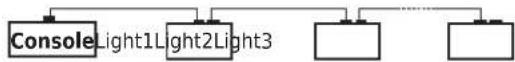
DMX512
- Install the units in a suitable position (laying or appending).
- Use standard XLR microphone cable chain your units together via the XLR connector on the rear of the units. For longer cable runs we suggest a terminator at the last fixture.
- Assign a DMX address to each the unit.
- Turn on all units' power, the units begins reset, then the unit begins working.
- Use DMX console to control your units.
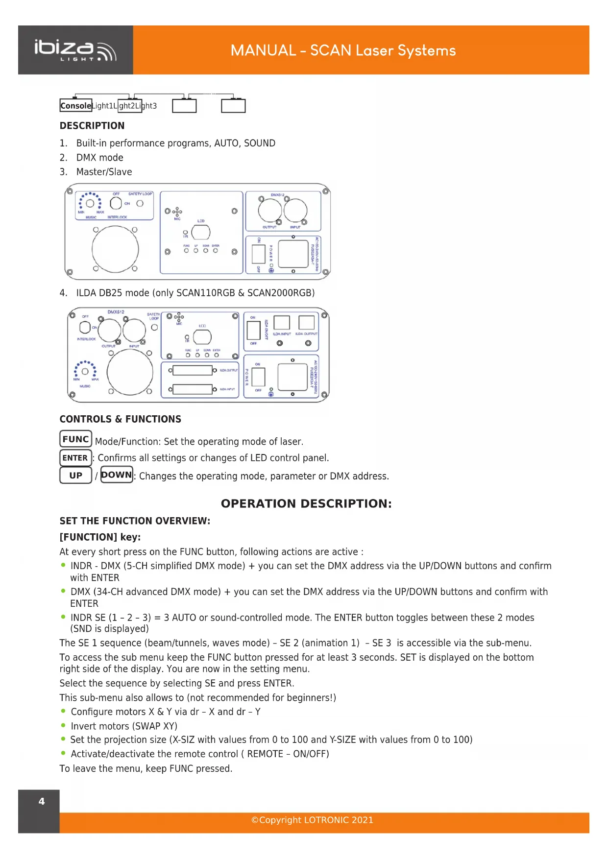
DESCRIPTION
- Built-in performance programs, AUTO, SOUND
- DMX mode
- Master/Slave
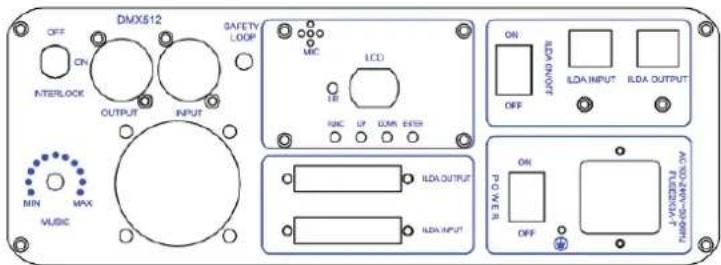
- ILDA DB25 mode (only SCAN110RGB & SCAN2000RGB)
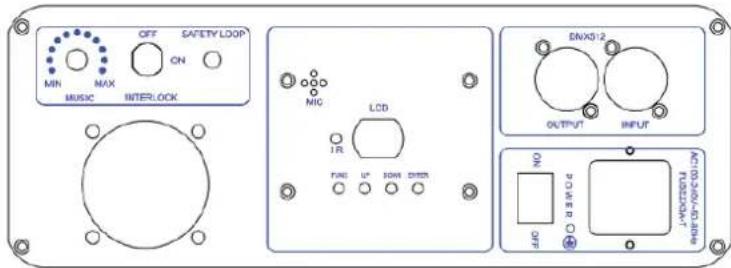
CONTROLS & FUNCTIONS
FUNC Mode/Function: Set the operating mode of laser.
ENTER: Confirms all settings or changes of LED control panel.
UP / DOWN: Changes the operating mode, parameter or DMX address.
OPERATION DESCRIPTION:
SET THE FUNCTION OVERVIEW:
[FUNCTION] key:
At every short press on the FUNC button, following actions are active :
- INDR - DMX (5-CH simplified DMX mode) + you can set the DMX address via the UP/DOWN buttons and confirm with ENTER
- DMX (34-CH advanced DMX mode) + you can set the DMX address via the UP/DOWN buttons and confirm with ENTER
- INDR SE (1 - 2 - 3) = 3 AUTO or sound-controlled mode. The ENTER button toggles between these 2 modes (SND is displayed)
The SE 1 sequence (beam/tunnels, waves mode) - SE 2 (animation 1) - SE 3 is accessible via the sub-menu.
To access the sub menu keep the FUNC button pressed for at least 3 seconds. SET is displayed on the bottom right side of the display. You are now in the setting menu.
Select the sequence by selecting SE and press ENTER.
This sub-menu also allows to (not recommended for beginners!)
- Configure motors X & Y via dr - X and dr - Y
• Invert motors (SWAP XY) - Set the projection size (X-SIZ with values from 0 to 100 and Y-SIZE with values from 0 to 100)
• Activate/deactivate the remote control (REMOTE - ON/OFF)
To leave the menu, keep FUNC pressed.
OVERVIEW OF PLAYBACK MODES:
There are multiple playback modes:
• Built-in Master mode: divided into three small playback modes.
1: mixed playback: Drawing scenes from each sequence in taking turn playback (can be set by setting the function).
2: Sequence playback: only play a sequence. (This mode for the temporary mode, restart laser will not automatically enter)
3: Scene playback: only play a scene. This mode for the temporary mode, restart laser will not automatically enter)
- Slave mode: divided into the following two slave modes:
1: DMX slave mode: Through the DMX signal line to follow the Master to play.
2: ILDA slave mode: Accept the ILDA signal control from the Master or laser console.
• DMX playback mode:
1: Easy DMX mode: 5 channels
Note: Simple DMX mode takes the built-in scenes of the laser directly without any further settings.
| CHANNEL DMX value DESCRIPTION | ||
| CH 1On/off power | 0 OFF | |
| 1-255 ON | ||
| CH2Act auto/sound | 0-127 AUTO | |
| 128-255 SOUND CONTROLLED | ||
| CH3Gallery Menu(scenes) | 0-15 1 gallery (0) | |
| 16-31 2 gallery (16) | ||
| 32-239 3 gallery (32) | ||
| 240-255 40 gallery (240) | ||
| CH4Scenes | 0-255 | Each value corresponds to a pattern, the value exceeds the number of patterns, the system with the largest number instead |
| CH5Colors | 0-31 RGB | |
| 32-63 red | ||
| 64-95 yellow | ||
| 96-127 green | ||
| 128-159 blueviolet | ||
| 160-191 blue | ||
| 191-223 purple | ||
| 224-255 white | ||
2: Professional DMX mode: 34 channels
Order 1: Professional DMX mode is available to the experienced lighting engineers, who are professional in DMX control, as well as the laser pattern scanning principle, if not, pls use simple DMX mode 4 channels
Order 2: DQF6 (the Bluetooth number) is a double-pattern laser system, and two patterns can be scanned at the same time. The following description is distinguished by pattern A and pattern B. For ease of view, the following points are shown in Table 1 and Table 2 respectively at the end of the manual.
- ILDA console mode: ILDA signal input, output ILDA effect (only SCAN110RGB & SCAN2000RGB). Effects library: Each effect library is stored as a sequence on the motherboard, they are:
- Geometric sequence (Gypsophalange filter);
- Wedding theme sequence;
- Christmas theme sequence;
- Beam sequence (no filter);
- Geometric sequence (Galaxy Nebula);
- 3D sequence (3D filter);
- Point circle sequence (dot circle filter);
- Long virtual point sequence (long virtual point filter);
LED DISPLAY INSTRUCTION:
{INTR}{DMX}{APP}{SET}{SND}{SEL} for status identification.
- {INTR} Indicates that the fixture is using the built-in effect. When the status flag is lit (INTR) alone, it is the built-in effect play mode.
- {DMX} indicates that the fixture is controlled by the DMX signal. The status flag is only bright (DMX) for the standard DMX control mode
• {INTR} {DMX} is a simple DMX mode that calls the built-in scenario via DMX signals. - {SET} indicates that the fixture is in the system setup state.
- {SND} indicates that the motion of the pattern is controlled by the sound when the fixture is in the built-in mode.
- {SEL} In the set state, the indicator is lit to indicate that the current setting option is enabled.
{INTR} the state of the digital display section
- {AL} indicates the mix mode in the built-in mode (the scene play is extracted from each sequence).
- {P###} Indicates the scene playback mode when the built-in mode is displayed. The displayed value is the scene number.
- {SE ##} indicates the sequence playback mode when the built-in mode is displayed, and the displayed value is the sequence number.
{DMX} the digital display part state.
{INTR} + {DMX} the digital display part state.
• {A ####} Indicates the DMX address code for the fixture.
{SET} the digital display part state.
- {SE ##} Indicates whether the digital display sequence is selected when the mixed mode of the built-in mode is used.
(Note: {SEL} status flag indicates whether the sequence is selected.)
• {DR- ||} indicates the X mirror setting.
• {DR- =} represents the Y mirror setting.
• {DR- = ||} represents XY offset.
- {x ####} represents the X projection amplitude, the digital part is the full scale percentage value
(Note: {SEL} can be adjusted through the button on the board).
- {y ###} denotes the Y projection amplitude (Note: same as above).
- {rOFF} Indicates whether or not the remote control function is turned off.
The virtual remote control of the mobile phone APP is the same as that described in the previous section.
Extinguished: After a few hours of no operation, the digital part of the display will go out (Note: the screen function with the specific model, some models do not have the function)
REMOTE CONTROL
Please operate the remote control within a distance of 6m and 30° between the remote and the appliance. Aim the remote at the sensor. Remove all obstacles between the remote and the sensor.
The remote control might not work properly if the sensor is exposed to strong sunshine.
If the remote control doesn't work properly, please check the batteries.
INSTALLING THE BATTERIES IN THE REMOTE CONTROL
- Place the remote face down on a flat surface.
- Push the compartment cover into the direction of the arrow.
- Slide the battery compartment open.
- Remove the old battery and install the new one (CR2032) with the plus (+) symbol facing up.
• Gently slide the battery compartment closed. It locks automatically.
RECOMMENDATIONS FOR BATTERIES

This symbol indicates that used batteries should not be disposed of with household waste but deposed correctly in accordance with your local regulations..
Batteries shall not be exposed to excessive heat such as sunshine, fire or the like.
When the internal batteries are not to be used, remove them to avoid damage caused by battery leakage or corrosion.
ATTENTION: Danger of explosion if battery is incorrectly placed. Only replace by the same or equivalent type.
WARNING : Do not swallow the battery. Danger of chemical burns. Keep new and old batteries out of the reach of children.
If the battery compartment doesn't close properly, stop using the product and keep it out of the reach of children.
If you are in doubt whether the batteries have been swallowed or introduced into any other part of the body, contact immediately a doctor.
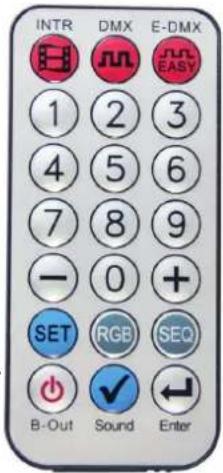
REMOTE CONTROL
• [INTR] key: Enter the mix mode built-in.
• [DMX] key: Professional DMX mode.
• [E-DMX] key: easy DMX mode.
• [1-9] key: digital number from 1 to 9
- In the built-in mix mode, press the [1-9] button to enter the scene playback mode. The number entered is the scene
- When the built-in sequence is played, press the [1-9] button to select the serial number.
- In DMX mode or E-DMX mode, press the digital button to set the address code.
- In the setting mode, you can select the projection range when setting the projection angle.
• [+][-] key:
- In the scene playback mode, press this key to adjust the scene number.
- Press this key to adjust the serial number in the sequence play mode.
- In DMX or E-DMX mode, press this key to adjust the address code.
- When setting mode, press this key to adjust the setting item.
- [SET]key:
- When the system is not in the set state, press 5 times to enter the system setting state.
- When the system is in the setting state, press this key to exit the system setting state.
• [RGB] key:
- Press this key to toggle the pattern colour. When the colour is changed, the display will temporarily display the currently set colour.
- This setting is set to temporary, and the system will return to the colour state (CLR) after the shut-down is restarted.
• [SEQ] key: Press this key to enter the sequence playback mode in built-in mode.
• [B-Out] key: Press this key to turn off the laser output.
• [Sound] key:
- In the built-in mode, press this key to set or cancel the voice.
- When setting a mixed sequence, you can select or cancel a sequence.
- You can select or cancel the mirror when setting the graphic X mirror, the graphic Y mirror, and the XY for the graphic.
- You can select or cancel the remote control when setting the remote control function.
- [ENTER] key: When entering a number, the value to be entered is less than 100, press this key to speed up the digital input.

IMPORTANT NOTE: Electric products must not be put into household waste. Please bring them to a recycling centre. Ask your local authorities or your dealer about the way to proceed.
MANUEL D'UTILISATION
LASER A USAGE EXCLUSIVEMENT PROFESSIONNEL
Classification Laser: .......Classe 3B
Note: Table 1: CH1-Ch17, pattern A's channel function, except for special instructions, only control the pattern A, pattern B is not controlled by these 17 channels:
| CHANNEL DMX value DESCRIPTION | ||
| CH 1 On/off power 0 OFF | ||
| 1-99 ON | ||
| 100-199 AUTO | ||
| 200-254 Retain | ||
| 255 Pattern A closed light, pattern B output light | ||
| CH2 Out of bounds and pattern size | 0-49 Out of bounds | |
| 50-99 Reentry | ||
| 100-149 Blanking | ||
| 150-199 Blanking+ pattern enlarge | ||
| 200-255 Retain | ||
| CH3 Gallery Menu (sences) | 0-15 1 gallery (0) | |
| 16-31 2 gallery (16) | ||
| 32-239 3 gallery (32) | ||
| 240-255 40 gallery (240) | ||
| CH4 Gallery choose 0-255 Each value corresponds to a pattern, when the value exceeds the number of patterns, the system uses the largest number | ||
| CH5 Patterns zooming 0 No zooming | ||
| 1-31 Zooming 1 | ||
| 32-63 Zooming 2 | ||
| 64-95 Zooming3 | ||
| 96-127 Zooming4 | ||
| 128-159 Zooming 5 | ||
| 160-191 Zooming 6 | ||
| 192-223 Zooming 7 | ||
| 224-255 Zooming8 | ||
| CH6 Patterns rotating | 0-63 Manual rotating | |
| 64-95 Rotating 1 | ||
| 96-127 Rotating 2 | ||
| 128-159 Rotating 3 | ||
| 160-191 Rotating 4 | ||
| 192-223 Rotating 5 | ||
| 224-255 Rotating 6 | ||
| CH7 Horizontal moving | 0-63 Manual moving | |
| 64-95 Horizontal 1 | ||
| 96-127 Horizontal 2 | ||
| 128-159 Horizontal 3 | ||
| 160-191 Horizontal 4 | ||
| 192-223 Horizontal 5 | ||
| 224-255 Horizontal 6 | ||
| CH8 Vertical moving | 0-63 Manual moving | |
| 64-95 vertical 1 | ||
| 96-127 vertical 2 | ||
| 128-159 vertical 3 | ||
| 160-191 vertical 4 | ||
| 192-223 vertical 5 | ||
| 224-255 vertical 6 | ||
| CH9 X axis Horizontal zooming | 0-63 Manual X zooming | |
| 64-95 X zooming 1 | ||
| 96-127 X zooming 2 | ||
| 128-159 X zooming 3 | ||
| 160-191 X zooming 4 | ||
| 192-223 X zooming 5 | ||
| 224-255 X zooming 6 | ||
| CH10 Y axis vertical zoom-ing | 0-63 Manual Y zooming | |
| 64-95 Y zooming 1 | ||
| 96-127 Y zooming 2 | ||
| 128-159 Y zooming 3 | ||
| 160-191 Y zooming 4 | ||
| 192-223 Y zooming 5 | ||
| 224-255 Y zooming 6 | ||
| CH11 Force Segmentation Color | 0 Patterns original colours | |
| 1-255 The length of the segmented colours | ||
| CH12 Patterns discolor 0-7 Original | ||
| 8-15 Red | ||
| 16-23 Yellow | ||
| 24-31 Green | ||
| 32-39 blue-violet | ||
| 40-47 Blue | ||
| 48-55 Purple | ||
| 56-63 White | ||
| 64-95 Red/green/blue discolour | ||
| 96-127 Blue violet/blue/purple discolour | ||
| 128-159 7 colours discolour | ||
| 160-191 RGB discolour | ||
| 192-223 Positive walking colour | ||
| 224-255 Reverse walking colour | ||
| CH13 Node and blanking control | 0-63 Normal blanking control | |
| 64-127 Patterns without blanking, flyback line banking | ||
| 128-159 Patterns and line without blanking | ||
| 160-255 Retain | ||
| CH14 The auxiliary function of the drawing control (used in conjunction with CH15) | 0-63(CH15) Manual gradually drawing | |
| 64-127/160-191(CH15) | The moving time of the pattern drawing gradually | |
| 192-255 The number of nodes that are drawn | ||
| CH15 Progressive control [CH15 must be used in conjunction with CH14] | 0-31 Forward hand-drawn gradually | |
| 32-63 Reverse manual drawing | ||
| 64-95 Extended drawing | ||
| 96-127 Contraction drawing | ||
EN
| 128-159 Both ends are zoomed at the same time | ||
| 160-191 Head and tail were zooming | ||
| 192-223 Walking drawing | ||
| 224-255 Turn over drawing | ||
| CH16 Auxiliary control of twist deformation effect channel | 0-255 0-255, the greater the value, the smaller the distortion. [Note: CH16 can control the degree of twist of the twist effect when zooming, rotating, moving, and twisting effects] | |
| CH17 Grating selection and projection amplitude control | 0-255 [0-19,grating 1] [20-39,grating 2].....[220-239,grating 12] [240-255,grating 13] Note: In each paragraph, the larger the value, the smaller the projection range | |
TABLE 2 (PATTERN B):
Note: Table 2: CH18-CH34, pattern B's channel function, except for special instructions, only control the pattern B, pattern A is not controlled by these 17 channels.
In order to simplify the operation, the functions correspond to pattern A, only special green parts are different.
| CHANNEL DMX value DESCRIPTION | ||
| CH 18 On/off power 0 off working | ||
| 1-99 Act auto | ||
| 100-199 Act sound | ||
| 200-254 retain | ||
| 255 Pattern A closed light, pattern B output light | ||
| CH19 Out of bounds and pattern size | 0-49 Out of bounds | |
| 50-99 Re-entry | ||
| 100-149 Blanking | ||
| 150-255 Retain | ||
| CH20 The distribution angle of each unit of the array | 0-99 the smaller the value of the segment, the larger the angular distribution of each unit, the gap is a positive gap | |
| 100-199 the smaller the value of the segment, the larger the angle distribution of each unit, the gap is the negative gap | ||
| 200-255 retain | ||
| CH21 Gallery choose 0-255 Each value corresponds to a pattern, when the value exceeds the number -ber of patterns, the system uses the largest number | ||
| CH22 Patterns zooming | 0 No zooming | |
| 1-31 Zooming 1 | ||
| 32-63 Zooming 2 | ||
| 64-95 Zooming3 | ||
| 96-127 Zooming4 | ||
| 128-159 Zooming 5 | ||
| 160-191 Zooming 6 | ||
| 192-223 Zooming 7 | ||
| 224-255 Zooming8 | ||
| CH23 Patterns rotating | 0-63 Manual rotating | |
| 64-95 Rotating 1 | ||
| 96-127 Rotating 2 | ||
| 128-159 Rotating 3 | ||
| 160-191 Rotating 4 | ||
| 192-223 Rotating 5 | ||
| 224-255 Rotating 6 | ||
| CH24 Horizontal moving | 0-63 Manual moving | |
| 64-95 Horizontal 1 | ||
| 96-127 Horizontal 2 | ||
| 128-159 Horizontal 3 | ||
| 160-191 Horizontal 4 | ||
| 192-223 Horizontal 5 | ||
| 224-255 Horizontal 6 | ||
| CH25 Vertical moving 0-63 Manual moving | ||
| CH26 X axis Horizontal zooming | 0-63 Manual X zooming | |
| 64-95 X zooming 1 | ||
| 96-127 X zooming 2 | ||
| 128-159 X zooming 3 | ||
| 160-191 X zooming 4 | ||
| 192-223 X zooming 5 | ||
| 224-255 X zooming 6 | ||
| CH27 Y axis vertical zooming | 0-63 Manual Y zooming | |
| 64-95 Y zooming 1 | ||
| 96-127 Y zooming 2 | ||
| 128-159 Y zooming 3 | ||
| 160-191 Y zooming 4 | ||
| 192-223 Y zooming 5 | ||
| 224-255 Y zooming 6 | ||
| CH28 Force Segmen-tation Color | 0 Patterns original colors | |
| 1-255 The length of the segmented colors | ||
| CH29 Patterns discolor 0-7 original | ||
EN
| CH30 Node and blank-ing controlArray control | 0-63 Normal blanking control | |
| 64-127 Patterns without blanking, flyback line banking | ||
| 128-159 Patterns and line without blanking | ||
| 160-191 Pattern A anchored in an array pattern of pattern B, pattern color setting same with A | ||
| 192-255 Pattern A anchored in an array pattern of pattern B, pattern color setting same with B | ||
| CH31 The auxiliary function of the draw-ing control (used in conjunction with CH32) | 0-63(CH32) Manual gradually drawing | |
| 64-127/160-191(CH32) | The moving time of the pattern drawing gradually | |
| 192-255(CH32) | The number of nodes that are drawn | |
| CH32 Progressive control [CH32 must be used in conjunc-tion with CH31];When the pattern A is voice-activated, the CH32 action will also become a voice-acti-vated state | 0-31 Forward hand-drawn gradually | |
| 32-63 Reverse manual drawing | ||
| 64-95 Extended drawing | ||
| 96-127 Contraction drawing | ||
| 128-159 Both ends are zoomed at the same time | ||
| 160-191 Head and tail were zooming | ||
| 192-223 Walking drawing | ||
| 224-255 Turn over drawing | ||
| CH33 Auxiliary control of twist deformation effect channel | 0-255 0-255, the greater the value, the smaller the distortion. [Note: CH33 can control the degree of twist of the twist effect when zooming, rotating, moving, and twisting effects] | |
| CH34 projection am-plitude controlNote: In each para-graph, the larger the value, the smaller the projection range | 0-255 (0-19),(20-39)......(220-239), (240-239),(240-255) | |
VIEW THE PRODUCTS ON OUR WEBSITE

SCAN500RGB

SCAN1100RGB

SCAN2000RGB

SCAN1100PINK
EN

Imported from China by LOTRONIC S.A.
Avenue Zénobe Gramme 9
B-1480 Saintes


www.ibiza-light.com