
HP EVS 561620 - Router MILWAUKEE - Free user manual and instructions
Find the device manual for free HP EVS 561620 MILWAUKEE in PDF.
| Product Type | Router |
| Brand | Milwaukee |
| Model | HP EVS 561620 (5616-20) |
| Supply Voltage | 120 V AC |
| Nominal Current | 13 A |
| Frequency | 60 Hz |
| No-Load Speed | 10,000 – 24,000 RPM (variable) |
| Maximum Power | 2 1/4 HP (≈ 1680 W) |
| Base Type | Bodygrip® (full-grip handle) |
| Variable Speed | Yes, dial from 1 to 7 |
| Soft Start | Yes |
| Electronic Protection | Against overloads |
| Compatible Plunge Base | Yes (ref. 48-10-5600, sold separately) |
| Double Insulation | Yes |
| Weight | Approximately 5 kg |
| Warranty | 5 years (United States and Canada) |
| Recommended Maintenance | Lubrication and brush replacement every 6 to 12 months |
| Safety | Trigger lock, emergency stop (ON/OFF switch) |
| Included Accessories | Collet chuck, mounting wrenches, edge guide (depending on version) |
Frequently Asked Questions - HP EVS 561620 MILWAUKEE
User questions about HP EVS 561620 MILWAUKEE
0 question about this device. Answer the ones you know or ask your own.
Ask a new question about this device
Download the instructions for your Router in PDF format for free! Find your manual HP EVS 561620 - MILWAUKEE and take your electronic device back in hand. On this page are published all the documents necessary for the use of your device. HP EVS 561620 by MILWAUKEE.
USER MANUAL HP EVS 561620 MILWAUKEE
WARNING READ ALL SAFETY WARNINGS AND ALL INSTRUCTIONS. Failure to
follow the warnings and instructions may result in electric shock, fire and/or serious injuries. Save all warnings and instructions for future reference. The term "power tool" in the warnings refers to your mains-operated (cored) power tool or battery-operated (cordless) power tool.
WORK AREA SAFETY
- Keep work area clean and well lit. Cluttered or dark areas invite accidents.
- Do not operate power tools in explosive atmospheres, such as in the presence of flammable liquids, gases or dust. Power tools create sparks which may ignite the dust or fumes.
- Keep children and bystanders away while operating a power tool. Distractions can cause you to lose control.
ELECTRICAL SAFETY
- Power tool plugs must match the outlet. Never modify the plug in any way. Do not use any adapter plugs with earthed (grounded) power tools. Unmodified plugs and matching outlets will reduce risk of electric shock.
- Avoid body contact with earthed or grounded surfaces such as pipes, radiators, ranges and refrigerators. There is an increased risk of electric shock if your body is earthed or grounded.
- Do not expose power tools to rain or wet conditions. Water entering a power tool will increase the risk of electric shock.
- Do not abuse the cord. Never use the cord for carrying, pulling or unplugging the power tool. Keep cord away from heat, oil, sharp edges or moving parts. Damaged or entangled cords increase the risk of electric shock.
- When operating a power tool outdoors, use an extension cord suitable for outdoor use. Use of a cord suitable for outdoor use reduces the risk of electric shock.
- If operating a power tool in a damp location is unavoidable, use a ground fault circuit interrupter (GFCI) protected supply. Use of an GFCI reduces the risk of electric shock.
PERSONAL SAFETY
- Stay alert, watch what you are doing and use common sense when operating a power tool. Do not use a power tool while you are tired or under the influence of drugs, alcohol or medication. A moment of inattention while operating power tools may result in serious personal injury.
- Use personal protective equipment. Always wear eye protection. Protective equipment such as dust mask, non-skid safety shoes, hard hat, or hearing protection used for appropriate conditions will reduce personal injuries.
-
Prevent unintentional starting. Ensure the switch is in the off-position before connecting to power source and/or battery pack, picking up or carrying the tool. Carrying power tools with your finger on the switch or energising power tools that have the switch on invites accidents.
-
Remove any adjusting key or wrench before turning the power tool on. A wrench or a key left attached to a rotating part of the power tool may result in personal injury.
- Do not overreach. Keep proper footing and balance at all times. This enables better control of the power tool in unexpected situations.
- Dress properly. Do not wear loose clothing or jewellery. Keep your hair, clothing and gloves away from moving parts. Loose clothes, jewellery or long hair can be caught in moving parts.
- If devices are provided for the connection of dust extraction and collection facilities, ensure these are connected and properly used. Use of dust collection can reduce dust-related hazards.
POWER TOOL USE AND CARE
- Do not force the power tool. Use the correct power tool for your application. The correct power tool will do the job better and safer at the rate for which it was designed.
- Do not use the power tool if the switch does not turn it on and off. Any power tool that cannot be controlled with the switch is dangerous and must be repaired.
- Disconnect the plug from the power source and/or the battery pack from the power tool before making any adjustments, changing accessories, or storing power tools. Such preventive safety measures reduce the risk of starting the power tool accidentally.
- Store idle power tools out of the reach of children and do not allow persons unfamiliar with the power tool or these instructions to operate the power tool. Power tools are dangerous in the hands of untrained users.
- Maintain power tools. Check for misalignment or binding of moving parts, breakage of parts and any other condition that may affect the power tool's operation. If damaged, have the power tool repaired before use. Many accidents are caused by poorly maintained power tools.
- Keep cutting tools sharp and clean. Properly maintained cutting tools with sharp cutting edges are less likely to bind and are easier to control.
- Use the power tool, accessories and tool bits etc. in accordance with these instructions, taking into account the working conditions and the work to be performed. Use of the power tool for operations different from those intended could result in a hazardous situation.
SERVICE
- Have your power tool serviced by a qualified repair person using only identical replacement parts. This will ensure that the safety of the power tool is maintained.
SPECIFIC SAFETY RULES
- Hold power tool by insulated gripping surfaces, because the cutter may contact its own cord. Cutting a "live" wire may make exposed metal parts of the power tool "live" and shock the operator.
- Use clamps or another practical way to secure and support the workpiece to a stable platform. Holding the work by your hand or against the body leaves it unstable and may lead to loss of control.
- Always wear safety goggles and dust mask. Use only in a well ventilated area. Using personal safety devices and in a safe environment reduce the risk for injury.
- Some woods contain preservatives that can be toxic. Take extra care to prevent inhalation and skin contact when working with these materials. Request, and follow, any safety information available from your material supplier.
- Always make sure the workpiece is free from nails, screws and other foreign objects. Keep the working edge away from the clamping surface. Cutting these objects can cause loss of control of the tool and damage to the bit.
- Never hold the workpiece in one hand and the tool in the other hand when using the tool. Never place hands near or below cutting surface. Clamping the material and guiding the tool with both hands is safer.
- Never use dull or damaged bits. Sharp bits must be handled with care. Damaged bits can break during use. Dull bits require more force to push the tool, which could cause the bit to break. Damaged bits can throw carbide pieces and burn the workpiece.
- After changing the bit or making any adjustments, make sure the collet nut and any other adjustment devices are securely tightened. Loose adjustment devices can unexpectedly shift, causing loss of control. Loose rotating components will be violently thrown. Watch for vibration or wobbling that could indicate an improperly installed bit.
- Maintain firm grip on router when starting motor to resist starting torque.
- Always keep the power supply cord away from moving parts on the tool. Keep the cord away from the direction of the cut.
- Never start the tool when the bit is in contact with the material. The bit cutting edge may grab the material causing loss of control of the tool.
- Never lay the tool down until the bit has come to a complete stop. The spinning bit can grab the surface and pull the tool out of your control.
- Never touch the bit during or immediately after use. After use the bit may be hot enough to burn bare skin.
- Never clamp the workpiece to a hard surface, such as concrete or stone. Contact with the bit could cause the tool to jump and loss of control.
-
Only operate the routers when held. Do not clamp or secure the router to a surface and hold the workpiece by hand.
-
Never use bits larger than the smallest of the openings in the base, sub-base, or dust collection port.
-
Do not loosen or remove the plunge base caps. Internal springs are under pressure. If loosened or removed, the plunge base caps and internal springs will become projectiles, which could cause injury.
-
Maintain labels and nameplates. These carry important information. If unreadable or missing, contact a MIL WAAKEE service facility for a free replace
-
WARNING: Some dust created by power sanding, sawing, grinding, drilling, and other construction activities contains chemicals known to cause cancer, birth defects or other reproductive harm. Some examples of these chemicals are:
-
lead from lead-based paint
crystalline silica from bricks and cement and other masonry products, and - arsenic and chromium from chemically-treated lumber.
Your risk from these exposures varies, depending on how often you do this type of work. To reduce your exposure to these chemicals: work in a well ventilated area, and work with approved safety equipment, such as those dust masks that are specifically designed to filter out microscopic particles.
| SYMBOLOLOGY | |
| Double Insulated | |
| V | Volts |
| ~ | Alternating Current |
| A | Amps |
| n0xxxxmin. | No Load Revolutions per Minute (RPM) |
| C US | Underwriters Laboratories, Inc. United States and Canada |
SPECIFICATIONS
| Cat. No. | Volts AC Ams | No Load RPM | Max HP |
| 5615-20* Bodygrip® | 120 11 24,000 | 1-3/4 | |
| 5616-20* Bodygrip® | 120 13 10,000 | -24,000 2-1/4 | |
| 5619-20 D-Handle | 120 11 24,000 | 1-3/4 | |
| 5625-20 Production | 120 15 10,000 | -22,000 3-1/2 |
Also compatible with plunge base 48-10-5600, available separately and in kits.

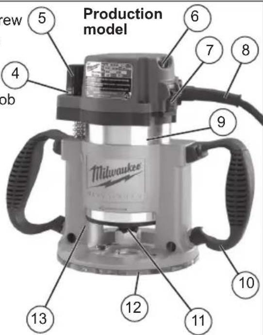
FUNCTIONAL DESCRIPTION
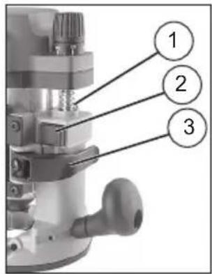
- Depth adjustment screw
- Motor release button
- Locking lever
- Scale
- Depth adjustment knob
- Variable speed dial (For Cat. No. 5616-20 only)
- On/Off switch
- Motor
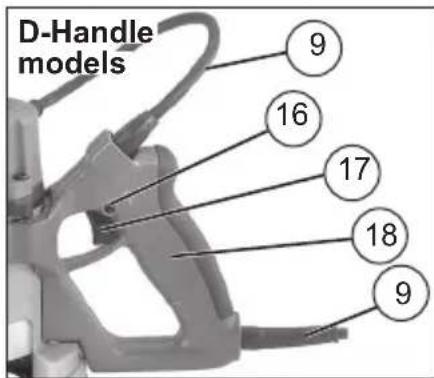
- Cord
- Body grip
- Strap
- Ball handle
- Collet assembly
- Sub-Base
15.Base - Lock button
- Trigger
- D-handle
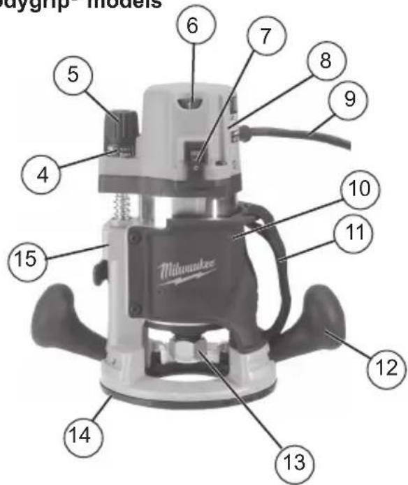
Bodygrip® models
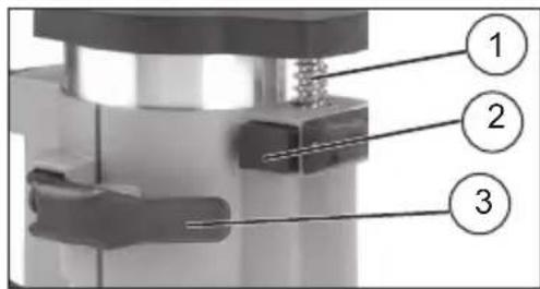
- Depth adjustment screw
- Motor release button
- Locking lever
- Scale
- Depth adjustment knob
- Variable speed dial
- On/Off switch
- Cord
- Motor
- Handle
- Collet assembly

- Sub-base
13.Base - Turret
- Depth stop rod release button
- Depth stop rod locking screw
- Plunge release lever
- Depth stop rod
- Depth stop rod adjustable pointer
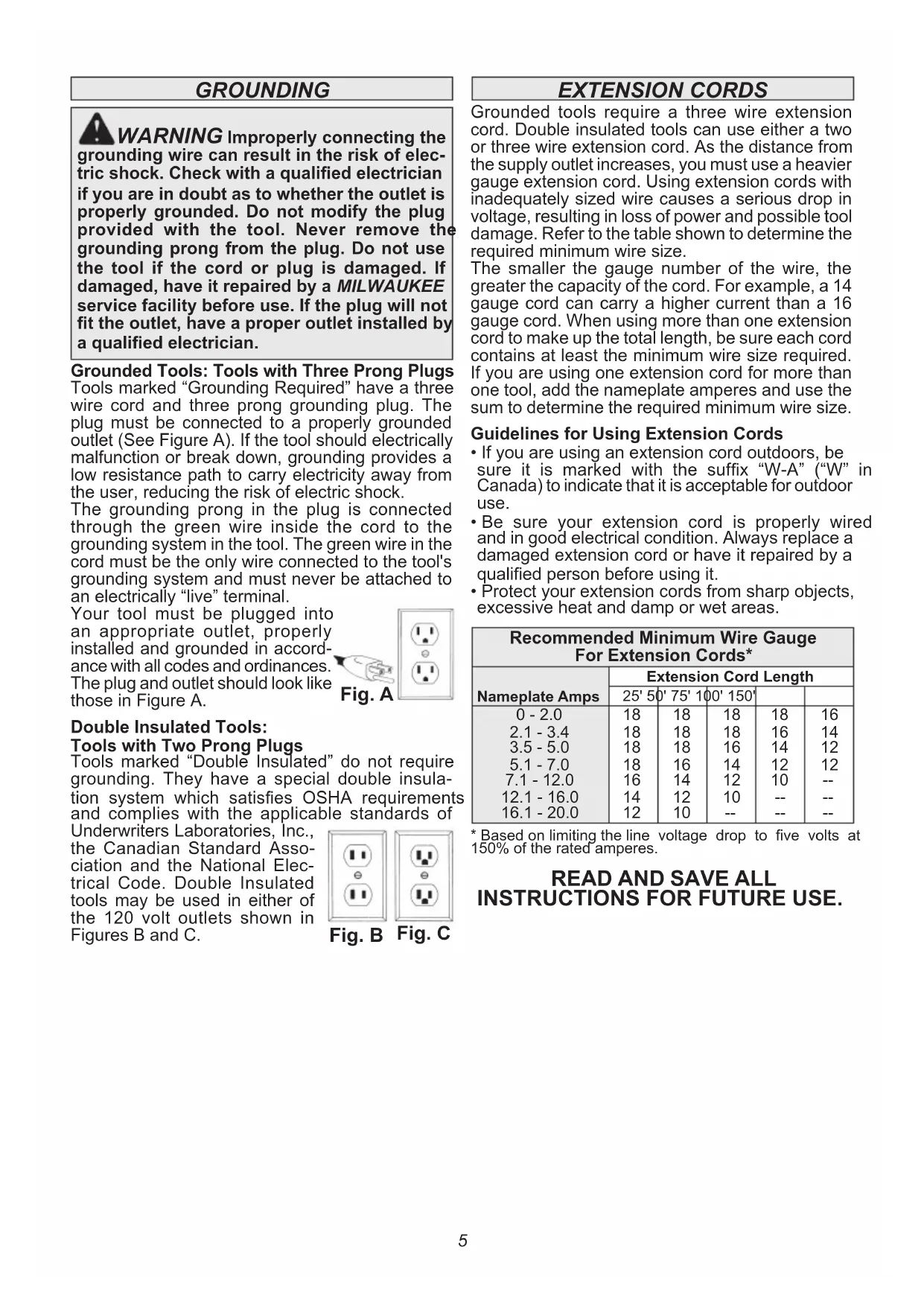
GROUNDING
WARNING Improperly connecting the grounding wire can result in the risk of electric shock. Check with a qualified electrician if you are in doubt as to whether the outlet is properly grounded. Do not modify the plug provided with the tool. Never remove the grounding prong from the plug. Do not use the tool if the cord or plug is damaged. If damaged, have it repaired by a MILWAUKEE service facility before use. If the plug will not fit the outlet, have a proper outlet installed by a qualified electrician.
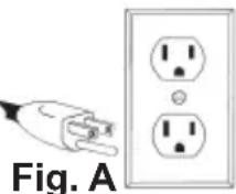
Grounded Tools: Tools with Three Prong Plugs
Tools marked "Grounding Required" have a three wire cord and three prong grounding plug. The plug must be connected to a properly grounded outlet (See Figure A). If the tool should electrically malfunction or break down, grounding provides a low resistance path to carry electricity away from the user, reducing the risk of electric shock.
The grounding prong in the plug is connected through the green wire inside the cord to the grounding system in the tool. The green wire in the cord must be the only wire connected to the tool's grounding system and must never be attached to an electrically "live" terminal.
Your tool must be plugged into an appropriate outlet, properly installed and grounded in accordance with all codes and ordinances. The plug and outlet should look like those in Figure A.
Double Insulated Tools: Tools with Two Prong Plugs
Tools marked "Double Insulated" do not require grounding. They have a special double insulation system which satisfies OSHA requirements and complies with the applicable standards of
Underwriters Laboratories, Inc., the Canadian Standard Association and the National Electrical Code. Double Insulated tools may be used in either of the 120 volt outlets shown in Figures B and C.
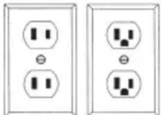
Fig.B Fig.C
EXTENSION CORDS
Grounded tools require a three wire extension cord. Double insulated tools can use either a two or three wire extension cord. As the distance from the supply outlet increases, you must use a heavier gauge extension cord. Using extension cords with inadequately sized wire causes a serious drop in voltage, resulting in loss of power and possible tool damage. Refer to the table shown to determine the required minimum wire size.
The smaller the gauge number of the wire, the greater the capacity of the cord. For example, a 14 gauge cord can carry a higher current than a 16 gauge cord. When using more than one extension cord to make up the total length, be sure each cord contains at least the minimum wire size required. If you are using one extension cord for more than one tool, add the nameplate amperes and use the sum to determine the required minimum wire size.
Guidelines for Using Extension Cords
- If you are using an extension cord outdoors, be sure it is marked with the suffix "W-A" ("W" in Canada) to indicate that it is acceptable for outdoor use.
- Be sure your extension cord is properly wired and in good electrical condition. Always replace a damaged extension cord or have it repaired by a qualified person before using it.
- Protect your extension cords from sharp objects, excessive heat and damp or wet areas.
| Recommended Minimum Wire Gauge For Extension Cords* | |||||
| Nameplate Amps | Extension Cord Length | ||||
| 25' 50' 75' 100' 150' | |||||
| 0 - 2.0 | 18 | 18 | 18 | 18 | 16 |
| 2.1 - 3.4 | 18 | 18 | 18 | 16 | 14 |
| 3.5 - 5.0 | 18 | 18 | 16 | 14 | 12 |
| 5.1 - 7.0 | 18 | 16 | 14 | 12 | 12 |
| 7.1 - 12.0 | 16 | 14 | 12 | 10 | -- |
| 12.1 - 16.0 | 14 | 12 | 10 | -- | -- |
| 16.1 - 20.0 | 12 | 10 | -- | -- | -- |
- Based on limiting the line voltage drop to five volts at 150% of the rated amperes.
READ AND SAVE ALL INSTRUCTIONS FOR FUTURE USE.
ASSEMBLY
WARNING To reduce the risk of injury always unplug tool before changing or removing accessories. Only use accessories specifically recommended for this tool. Others may be hazardous.
Collets
The collet must be attached to the collet nut before it is put into the collet shaft. Be sure that the size of the collet matches the size of the bit shank being used. If the wrong size bit shank is used, the collet may break. For attaching or detaching the collet nut to the collet, follow the illustrated instructions on this page.
Attaching Collet to Collet Nut
To assemble, place the narrow end of the collet on an even surface. Take the nut and place it over the collet.
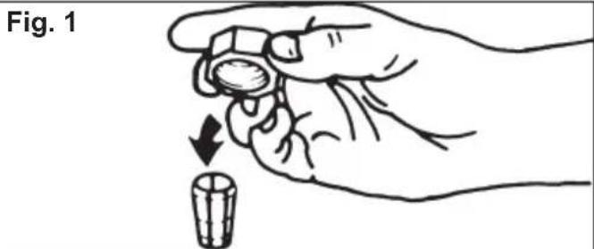
Position nut squarely over collet with the smaller opening of the nut facing up.
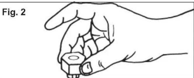
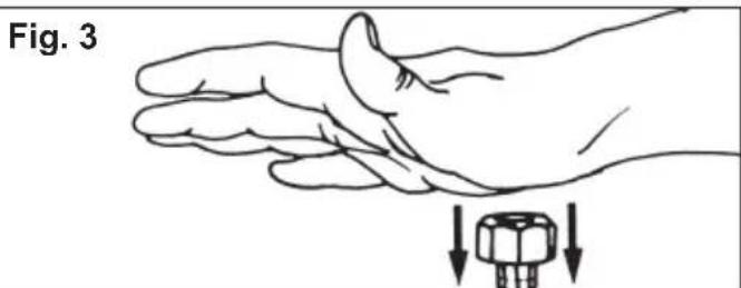
Snap nut and collet together by firmly applying downward pressure into assembly with palm of hand.
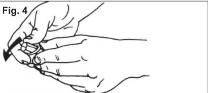
To remove collet from nut, hold nut firmly with one hand and press the collet to one side with the other hand.
WARNING Pressing the motor release button will cause the motor housing to drop down, which may cause personal injury or damage to the tool or workpiece. Make sure your hand is firmly on the motor when pressing the button.
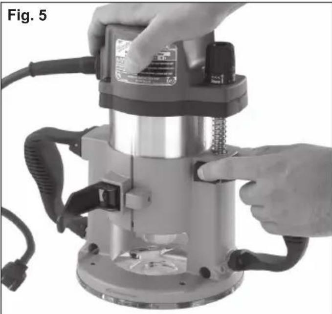
Installing/Removing the Motor
- Unplug the tool. Make sure the locking lever is fully open.
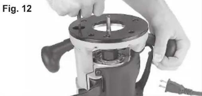
- Align the depth adjustment screw on the motor with the hole on the base.
- Press and hold the motor release button and lower the motor into the base to the desired depth. NOTE: The plunge base does not have a motor release button. Release the locking lever and pull out the motor.
- Release the motor release button and push in the locking lever to the fully closed position.
- To remove the motor, fully open the locking lever, grasp the motor, press and hold the motor release button, and pull out the motor.

Installing/Removing Edge Guide
To install an edge guide, loosen the two rod screws. Insert the edge guide rods into the rod holes and tighten the rod screws.


Installing/Removing Sub-bases
Fixed sub-bases (black):
To remove the sub-base, remove the sub-base screws. To install the sub-base, secure it with the sub-base screws.
Adjustable sub-bases (clear):
To ensure the sub-base is centered, use the centering cone and pin whenever tightening, adjusting, or changing the adjustable sub-base.
- Unplug the tool.
- Install the sub-base and screws, but do not tighten them.
- Lower the motor until the collet is about 1" above the base.
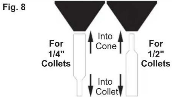
- With the router upside down, insert the pin into the cone, then into the collet (see Fig. 8 for correct orientation). Tighten the collet.
- Push the cone down firmly. The sub-base will center.
- While pressing down on the cone, tighten the sub-base screws.
- Remove the centering pin from the collet. Save the pin and cone for future use.
- To remove the sub-base, remove the sub-base screws.
WARNING To reduce the risk of injury, do not use the dust collection port when plunge cutting if the bit is larger than the port opening (1-3/8"). If a rotating router bit contacts the dust collection port, the port will break and flying debris may cause injury.
Installing the Dust Collection Port (not available on Cat. No. 5625-20)
- If an edge guide has been installed, it must be removed temporarily to install the dust collection port.
- Loosen the rod screws.
- Place the router upright and set the circle into the base (Fig. 9).
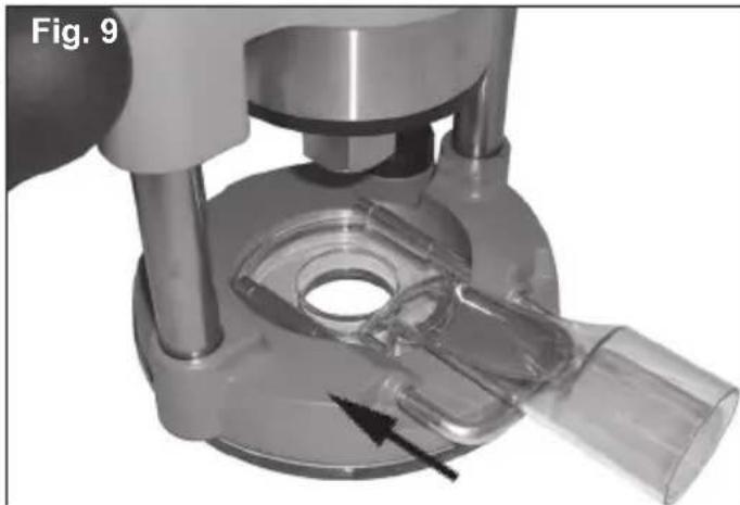
- Slide the rods through the base rod holes and into the port rod holes.
NOTE: Use either the rods supplied with the dust collection port or rods from a MIL WAAUKEE edge guide.
- Tighten the rod screws.
- Twist a vacuum hose into the end of the port.
Templet Guides
A 1-3/16" center hole sub-base is needed to use a template guide.
To install a templet guide, insert the guide into the center hole of a 1-3/16" router base and secure according to the templet guide instructions.
WARNING To reduce the risk of injury, wear safety goggles or glasses with side shields.
Always unplug the tool before attaching or removing accessories or making adjustments. Use only specifically recommended accessories. Others may be hazardous.
Never use bits larger than the smallest of the openings in the base, sub-base, or dust collection port.
Installing the Bit
It is not necessary to remove the motor from the base to install a collet assembly or a bit. If removal of the base is desired, see previous section. Always remove wood chips, dust or other foreign materials from the collet shaft and collet assembly before assembling.
Insert the collet assembly into the collet shaft. Insert the bit shank into the collet as follows:
- Unplug the tool.
- Insert the bit shank into the collet as far as it will go.
-
Back the bit shank out slightly to avoid bottoming
-
Be sure there is a minimum of 1/16" between the bottom of the collet assembly and the radius to the cutting portion of the bit (Fig. 10).

- Be sure that the collet is not clamped to a fluted section on the bit shank. The collet should be clamped to a solid part on the bit shank to ensure a tight grip.
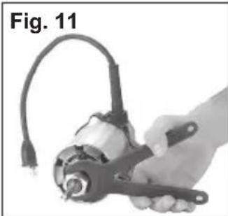
To tighten the bit in the collet assembly, use two wrenches.
NOTE: Never tighten a collet assembly without inserting a bit shank of the proper size. This may damage the collet.
Removing the Bit
- Unplug the tool.
- Loosen the collet nut from the collet shaft using two wrenches.
- Once loose, unscrew the collet nut by hand until it feels tight again.
- Use the wrenches again until the bit shank can be pulled out.
OPERATION
WARNING To reduce the risk of injury, wear safety goggles or glasses with side shields.
Unplug the tool before changing accessories or making adjustments.
Never make adjustments while the router is running.
DO NOT use the router if the locking lever does not hold the motor securely in the base. NEVER use the Plunge Base Router models in a router table.
Adjusting the Depth of Cut
Bodygrip, D-Handle and Production bases:
The tool depth can be adjusted by using the depth adjustment knob or a 3/8" socket wrench with an extension, or the Above-the-table Depth Wrench (Cat. No. 49-96-0370).
When using the depth adjustment knob, fully open the locking lever and rotate knob to the desired depth of cut. One revolution of the depth adjustment knob is equal to 0.2^ . For fine adjustments less than 5 / 32^ , use the independent scale on the depth adjustment knob.
For deeper cuts:
- Align the "0" on the scale with the arrow on the tool.
- Rotate depth adjustment knob clockwise to desired depth measurement.
For shallower cuts:
- Align the desired depth measurement with the arrow on the tool.
- Rotate depth adjustment knob counterclockwise to "0."
Push in locking lever to fully closed position when finished adjusting.
When using a socket wrench, place the router upside down on a flat surface and fully open the locking lever. Insert a 3/8 socket wrench into the hole on the base and turn to desired depth. Push in locking lever to fully closed position.
Plunge base:
- Unplug the tool.
- Install the bit.
- Press the plunge release lever and push down on the handles until the bit touches the workpiece.
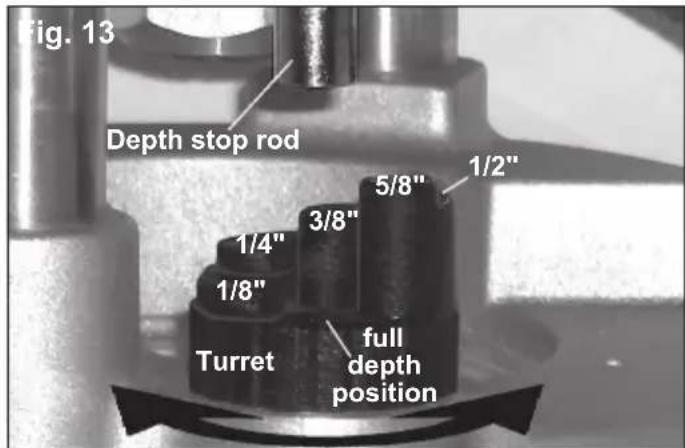
- Loosen the depth stop rod locking screw.
- Turn the turret so the full depth position is directly below the rod
- Press the depth stop rod release button to lower the rod. It should rest on the full depth position of the turret.
- Place the adjustable pointer on "0".
- Press in the depth stop rod release button Move the rod up to the desired depth of cut.
- Use the depth adjustment knob to finely tune the depth of cut.
10.Tighten the depth stop rod locking screw. - To obtain the cut making multiple passes, rotate the turret to a higher step. Each step is 1/8"
NOTE: A fine finish can be made using the turret and multiple passes.
Holding the Tool
These tools should be held using both hands at all times for maximum control.
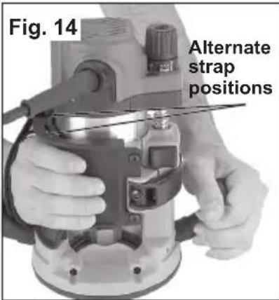
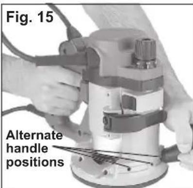
For Bodygrip® bases:
You can hold this tool using the body grip and ball handle or both ball handles. The body grip features an adjustable strap, which can be attached in two different positions for maximum control and comfort.
One handle on these bases may be adjusted to three different positions for maximum control and comfort.
For D-Handle base:
Grip the D-handle with one hand and place the other on the ball handle. One handle on these bases may be adjusted to three different positions for maximum control and comfort.
For Plunge and Production bases:

WARNING To reduce the risk of
injury, NEVER use the Plunge Base Router in a router table.

WARNING To reduce the risk of
injury, wear safety goggles or glasses with side shields.
To reduce the risk of injury, keep hands, body and cord away from the bit and all moving parts.
Before plugging the tool into a power outlet, make sure the on/off switch is in the "O" position.
Starting and Stopping Router Motor
For Cat. No. 5615-20, 5616-20 and 5625-20:
- To start the motor, place the router so the bit is away from you and not in contact with the workpiece. Grasp the tool firmly and push the On/Off switch to the "I" position.

-
To stop the motor, place the router so the bit is away from you and push the On/Off switch to the "O" position. Hold the tool until the bit stops turning. For Cat. No. 5619-20:
-
Push the On/Off switch to the "I" position.
- To start the motor, place the router so the bit is away from you and not in contact with the workpiece. Grasp the tool firmly and pull the trigger.
- To stop the motor, release the trigger.
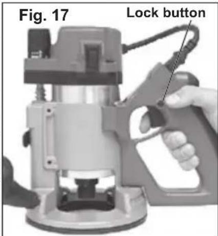
Locking the D-handle Base Trigger
The lock button holds the trigger in the ON position for continuous use.
- To lock the trigger, hold in the lock button while pulling the trigger. Release the trigger.
- To unlock the trigger, pull the trigger and release. The lock button will pop out.
NOTE: D-handle base does not fit Cat.No.5625-20.
Electronic Overload Protection
(For Cat. No. 5616-20 and 5625-20 only)
These tools are equipped with an electronic overload protection feature.
If the motor shuts off during use, remove the bit from the workpiece and push the On/Off switch to the "O" position for three (3) seconds. This will reset the electronics in the tool. The tool can then be restarted.
Using the Variable Speed Dial
(For Cat. No. 5616-20 and 5625-20 only)
The variable speed dial allows the user to adjust the rotating speed (RPM) of the tool.
Variable speed dial settings range from numbers (7) seven through (1) one. Higher numbers correspond to higher speeds and lower number correspond to lower speeds.
To change the speed, set the variable speed control dial to the desired number. Soft Start
(For Cat. No. 5616-20 and 5625-20 only)
The Soft-Start feature reduces the amount of torque reaction to the tool and the user. This feature gradually increases the motor speed up from zero to the speed set by the variable speed dial.
Feedback Control
(For Cat. No. 5616-20 and 5625-20 only)
The electronic speed control system allows the tool to maintain constant speed between no-load and load conditions.
WARNING To reduce the risk of injury, always wear eye protection.
To reduce the risk of explosion, electric shock and property damage, always check the work area for hidden pipes and wires before routing.
Making the Cut
Before cutting, check that all adjustments are tight and the locking lever is fully closed and secure.
The speed and depth of cut will depend largely on the type of material being worked. Keep the cutting pressure constant but do not use excessive force on the router so the motor speed slows excessively. It may be necessary on exceptionally hard woods or problem materials to make more than one pass to get the desired depth of cut.
Before beginning the cut on the actual workpiece, make a sample cut on a scrap piece of lumber. This will show you exactly how the cut will look as well as enable you to check dimensions. Always be sure the workpiece is secure before routing. When routing edges, the router should be held firmly down and against the work using handles.
Since the cutter rotates clockwise, more efficient cutting will be obtained if the router is moved from left to right as you stand facing the work. The arrows on the base of the tool indicate the direction of bit rotation. When working on the outside of an edge, move router in a counterclockwise direction.
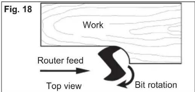
When working on an inside edge, move the router in a clockwise direction.
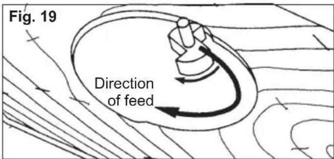
Moving the router in the opposite direction is known as "climb cutting."
WARNING To reduce the risk of injury, avoid "climb cutting." Climb cutting increases the potential for loss of control of the tool and damage to the workpiece. If climb cutting can not be avoided, use extreme caution.
WARNING To reduce the risk of injury, do not use a plunge base router if the motor does not rise automatically when the plunge release lever is pressed.
Plunge Cutting
- Set the depth of cut.
- Securely clamp the workpiece.
- Press the plunge release lever and raise the bit so it does not contact the workpiece.
- Hold the handles securely and turn on the motor. Wait for the motor to reach full speed (or the speed indicated by the variable speed dial).
- Press the plunge release lever and slowly lower the bit into the workpiece until the depth stop rod contacts the turret. Release the plunge release lever.
- Begin moving the router, keeping the sub-base flat on the workpiece. Keep the cord and dust collection hose out of the path of the router.
- When finished, press the plunge release lever and raise the bit out of the workpiece. Turn the motor off and wait for the bit to stop turning.
MAINTENANCE
WARNING To reduce the risk of injury always unplug your tool before performing any maintenance. Never disassemble the tool or try to do any rewiring on the tool's electrical system. Contact a MILWAUKEE service facility for ALL repairs.
Maintaining Tools
Keep your tool in good repair by adopting a regular maintenance program. Before use, examine the general condition of your tool. Inspect guards, switches, tool cord set and extension cord for damage. Check for loose screws, misalignment, binding of moving parts, improper mounting, broken parts and any other condition that may affect its safe operation. If abnormal noise or vibration occurs, turn the tool off immediately and have the problem corrected before further use. Do not use a damaged tool. Tag damaged tools "DO NOT USE" until repaired (see "Repairs").
Under normal conditions, relubrication is not necessary until the motor brushes need to be replaced. After six months to one year, depending on use, return your tool to the nearest MIL WAAKEE service facility for the following:
- Lubrication
- Brush inspection and replacement
- Mechanical inspection and cleaning (gears, spindles, bearings, housing, etc.)
- Electrical inspection (switch, cord, armature, etc.)
- Testing to assure proper mechanical and electrical operation
WARNING To reduce the risk of injury, electric shock and damage to the tool, never immerse your tool in liquid or allow a liquid to flow inside the tool.
Cleaning
Clean dust and debris from vents. Keep the tool handles clean, dry and free of oil or grease. Use only mild soap and a damp cloth to clean your tool since certain cleaning agents and solvents are harmful to plastics and other insulated parts. Some of these include: gasoline, turpentine, lacquer thinner, paint thinner, chlorinated cleaning solvents, ammonia and household detergents containing ammonia. Never use flammable or combustible solvents around tools.
Repairs
If your tool is damaged, return the entire tool to the nearest service center.
ACCESSIONS
WARNING To reduce the risk of injury, always unplug the tool before attaching or removing accessories. Use only specifically recommended accessories. Others may be hazardous.
For a complete listing of accessories refer to your MILWAUKEE Electric Tool catalog or go on-line to www.milwaukeetool.com. To obtain a catalog, contact your local distributor or a service center.
LIMITED WARRANTY - USA AND CANADA
Every MILWAUKEE power tool (including cordless product - tool, battery pack(s) - see separate & distinct CORDLESS BATTERY PACK LIMITED WARRANTY statements & battery charger and Work Lights) is warranted to the original purchaser only to be free from defects in material and workmanship. Subject to certain exceptions, MILWAUKEE will repair or replace any part on an electric power tool which, after examination, is determined by MILWAUKEE to be defective in material or workmanship for a period of five (5) years after the date of purchase unless otherwise noted. Return of the power tool to a MILWAUKEE factory Service Center location or MILWAUKEE Authorized Service Station, freight prepaid and insured, is required. A copy of the proof of purchase should be included with the return product. This warranty does not apply to damage that MILWAUKEE determines to be from repairs made or attempted by anyone other than MILWAUKEE authorized personnel, misuse, alterations, abuse, normal wear and tear, lack of maintenance, or accidents.
*The warranty period for, Job Site Radios, M12™ Power Port, M18™ Power Source, and Trade Titan™ Industrial Work Carts is one (1) year from the date of purchase. The warranty period for a LED Work Light and LED Upgrade Bulb is a limited LIFETIME warranty to the original purchaser only, if during normal use the LED bulb fails the Work Light or Upgrade Bulb will be replaced free of charge.
*This warranty does not cover Air Nailers & Stapler, Airless Paint Sprayer, Cordless Battery Packs, Gasoline Driven Portable Power Generators, Hand Tools, Hoist - Electric, Lever & Hand Chain, M12™ Heated Jackets, Reconditioned product and Test & Measurement products. There are separate and distinct warranties available for these products.
Warranty Registration is not necessary to obtain the applicable warranty on a MILWAUKEE power tool product. The manufacturing date of the product will be used to determine the warranty period if no proof of purchase is provided at the time warranty service is requested.
ACCEPTANCE OF THE EXCLUSIVE REPAIR AND REPLACEMENT REMEDIES DESCRIBED HEREIN IS A CONDITION OF THE CONTRACT FOR THE PURCHASE OF EVERY MILWAUKEE PRODUCT. IF YOU DO NOT AGREE TO THIS CONDITION, YOU SHOULD NOT PURCHASE THE PRODUCT. IN NO EVENT SHALL MILWAUKEE BE LIABLE FOR ANY INCIDENTAL, SPECIAL, CONSEQUENTIAL OR PUNITIVE DAMAGES, OR FOR ANY COSTS, ATTORNEY FEES, EXPENSES, LOSSES OR DELAYS ALGEGD TO BE AS A CONSEQUENCE OF ANY DAMAGE TO, FAILURE OF, OR DEFECT IN ANY PRODUCT INCLUDING, BUT NOT LIMITED TO, ANY CLAIMS FOR LOSS OF PROFITS. SOME STATES DO NOT ALLOW THE EXCLUSION OR LIMITATION OF INCIDENTAL OR CONSEQUENTIAL DAMAGES, SO THE ABOVE LIMITATION OR EXCLUSION MAY NOT APPLY TO YOU. THIS WARRANTY IS EXCLUSIVE AND IN LIEU OF ALL OTHER EXPRESS WARRANTYES, WRITTEN OR ORAL. TO THE EXTENT PERMITTED BY LAW, MILWAUKEE DISCLAIMS ANY IMPLIED WARRANTYES, INCLUDING WITHOUT LIMITATION ANY IMPLIED WARRANTY OF MERCHANTABILITY OR FITNESS FOR A PARTICULAR USE OR PURPOSE; TO THE EXTENT SUCH WARRANTYER IS NOT PERMITTED BY LAW, SUCH IMPLIED WARRANTYES ARE LIMITED TO THE DURATION OF THE APPLICABLE EXPRESS WARRANTY AS DESCRIBED ABOVE. SOME STATES DO NOT ALLOW LIMITATIONS ON HOW LONG AN IMPLIED WARRANTY LASTS, SO THE ABOVE LIMITATION MAY NOT APPLY TO YOU, THIS WARRANTY GIVES YOU SPECIFIC LEGAL RIGHTS, AND YOU MAY ALSO HAVE OTHER RIGHTS WHICH VARY FROM STATE TO STATE.
This warranty applies to product sold in the U.S.A. and Canada only.
Please consult the 'Service Center Search' in the Parts & Service section of MILWAUKEE's website www. milwaukeetoole or call 1.800.SAWDUST (1.800.729.3878) to locate your nearest service facility for warranty and non-warranty service on a Milwaukee electric power tool.
LIMITED WARRANTY - MEXICO, CENTRAL AMERICA AND CARIBBEAN
TECHTRONIC INDUSTRIES' warranty is for 5 year since the original purchase date.
This warranty card covers any defect in material and workmanship on this Power Tool.
To make this warranty valid, present this warranty card, sealed/stamped by the distributor or store where you purchased the product, to the Authorized Service Center (ASC). Or, if this card has not been sealed/stamped, present the original proof of purchase to the ASC.
Call toll-free 1 800 832 1949 to find the nearest ASC, for service, parts, accessories or components.
Procedure to make this warranty valid
Take the product to the ASC, along with the warranty card sealed/stamped by the distributor or store where you purchased the product, and there any faulty piece or component will be replaced without cost for you. We will cover all freight costs relative with this warranty process.
Exceptions
This warranty is not valid in the following situations:
a) When the product is used in a different manners from the end-user guide or instruction manual.
b) When the conditions of use are not normal.
c) When the product was modified or repaired by people not authorized by TECHTRONIC INDUSTRIES.
Note: If cord set is damaged, it should be replaced by an Authorized Service Center to avoid electric risks.
SERVICE AND ATTENTION CENTER
Model:Presidente Mazarik 29 Piso 7,11570 Chapultepec Morales
Miguel Hidalgo, Distrito Federal, Mexico
Dateof 32pss8-3547
DistributerTeDSareStammerCIALIZED BY:
TECHTRONIC INDUSTRIES MEXICO, S.A. DE C.V
Av Presidente Mazarik 29 Piso 7, 11570 Chapultepec Morales
Miguel Hidalgo, Distrito Federal, Mexico
RÉGLES DE SECURITÉ GÉNÉRALES RELATIVES AUX OUTILS ELECTRIQUES

A V A R T I S S E M E N T L I R E T O U T ES L ES RÉGLES ET INSTRUCTIONS DE SECURITÉ.
Para Cat. No. 5625-20:
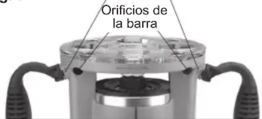
Fig. 7
Tornillos de barra
Instalacion/Extracion de la Sub-base Sub-bases fijas (negras)::
Para Cat. No. 5619-20:
UNITED STATES MILWAUKEE Service
MILWAUKEE prides itself in producing a premium quality product that is NOTHING BUT HEAVY DUTY. Your satisfaction with our products is very important to us! If you encounter any problems with the operation of this tool, or you would like to locate the factory Service/Sales Support Branch or authorized service station nearest you, please call... Additionally, we have a nationwide network of authorized Distributors ready to assist you with your tool and accessory needs. Check your "Yellow Pages" phone directory under "Tools-Electric" for the names & addresses of those nearest you or see the 'Where To Buy' section of our website.
1-800-SAWDUST
(1.800.729.3878)
Monday-Friday
7:00AM-6:30PM
Central Time
or visit our website at
www.milwaukeetool.com
For service information, use the 'Service Center Search' icon found in the 'Parts & Service' section.
Contact our Corporate After Sales Service Technical Support about ...
Technical Questions
Service/Repair Questions
Warranty
call: 1-800-SAWDUST
fax: 1.800.638.9582
email: metproductsupport@milwaukeetool.com
Register your tool online at www.milwaukeetool.com and...
- receive important notifications regarding your purchase
- ensure that your tool is protected under the warranty
become a HEAVY DUTY club member
CANADA - Service MILWAUKEE
MILWAUKEE prides itself in producing a premium quality product that is NOTHING BUT HEAVY DUTY. Your satisfaction with our products is very important to us!
If you encounter any problems with the operation of this tool, or you would like to locate the factory Service/Sales Support Branch or authorized service station nearest you, please call...
1.800.268.4015
Monday-Friday 7:00-4:30 CST
fax: 866.285.9049
Milwaukee Electric Tool (Canada) Ltd
140 Fernstaff Court, Unit 4 18129 111 Avenue NW
Vaughan, ON L4K 3L8 Edmonton, AB T5S 2P2
Additionally, we have a nationwide network of authorized Distributors ready to assist you with your tool and accessory needs. Call 1.800.268.4015 to find the names and addresses of the closest retailers or consult "Where to buy" on our Web site www.milwaukeetool.com
Milwaukee Electric Tool (Canada) Ltd
140 Fernstaff Court, Unit 4 18129 111 Avenue NW Vaughan, ON L4K 3L8 Edmonton, AB T5S 2P2
Lunes a Viernes (9am a 6pm)
O contactanos en www.milwaukeetool.com.mx
MILWAUKEE ELECTRIC TOOL CORPORATION
13135 West Lisbon Road • Brookfield, Wisconsin, U.S.A. 53005


- WORK AREA SAFETY
- ELECTRICAL SAFETY
- PERSONAL SAFETY
- POWER TOOL USE AND CARE
- SERVICE
- SPECIFIC SAFETY RULES
- FUNCTIONAL DESCRIPTION
- GROUNDING
- Double Insulated Tools: Tools with Two Prong Plugs
- EXTENSION CORDS
- Guidelines for Using Extension Cords
- READ AND SAVE ALL INSTRUCTIONS FOR FUTURE USE.
- ASSEMBLY
- Collets
- Attaching Collet to Collet Nut
- Installing/Removing Edge Guide
- Installing/Removing Sub-bases
- Installing the Dust Collection Port (not available on Cat. No. 5625-20)
- Templet Guides
- Installing the Bit
- Removing the Bit
- OPERATION
- Adjusting the Depth of Cut
- Bodygrip, D-Handle and Production bases:
- Plunge base:
- Holding the Tool
- For Bodygrip® bases:
- For D-Handle base:
- For Plunge and Production bases:
- Starting and Stopping Router Motor
- Locking the D-handle Base Trigger
- Electronic Overload Protection
- (For Cat. No. 5616-20 and 5625-20 only)
- Using the Variable Speed Dial
- Feedback Control
- Making the Cut
- Plunge Cutting
- MAINTENANCE
- Maintaining Tools
- Cleaning
- Repairs
- ACCESSIONS
- LIMITED WARRANTY - USA AND CANADA
- LIMITED WARRANTY - MEXICO, CENTRAL AMERICA AND CARIBBEAN
- Procedure to make this warranty valid
- Exceptions
- RÉGLES DE SECURITÉ GÉNÉRALES RELATIVES AUX OUTILS ELECTRIQUES
- A V A R T I S S E M E N T L I R E T O U T ES L ES RÉGLES ET INSTRUCTIONS DE SECURITÉ.
- Instalacion/Extracion de la Sub-base Sub-bases fijas (negras)::
- UNITED STATES MILWAUKEE Service
- 1-800-SAWDUST
- Contact our Corporate After Sales Service Technical Support about ...
- Register your tool online at www.milwaukeetool.com and...
- CANADA - Service MILWAUKEE
- Milwaukee Electric Tool (Canada) Ltd
- MILWAUKEE ELECTRIC TOOL CORPORATION
Brand : MILWAUKEE
Model : HP EVS 561620
Category : Router