DLR1060 - Talkie Walkie MOTOROLA - Free user manual and instructions
Find the device manual for free DLR1060 MOTOROLA in PDF.

User questions about DLR1060 MOTOROLA
0 question about this device. Answer the ones you know or ask your own.
Ask a new question about this device
Download the instructions for your Talkie Walkie in PDF format for free! Find your manual DLR1060 - MOTOROLA and take your electronic device back in hand. On this page are published all the documents necessary for the use of your device. DLR1060 by MOTOROLA.
USER MANUAL DLR1060 MOTOROLA
natural_image
Black motorola with a rotary dial and antenna, no visible text or symbols on the device body.
DLR1020, DLR1060 models
Open Source Software Legal Notices:
This Motorola product contains Open Source Software. For more information regarding licenses, acknowledgements, required copyright notices and other usage terms, refer to the documentation for this Motorola product at:
www.motorolasolutions.com/DLR
CONTENTS
Contents....1
Product Safety....3
Acoustic Safety 3
Introduction 4
Package Contents. 4
FCC Licensing Information .....6
Batteries and Chargers Safety
Information....7
Operational Safety Guidelines.....8
Radio Overview....9
Parts Of The Radio .....9
Power Button 10
Top Button 10
Volume Control (+/-) Button .....10
Audio Accessory Connector .....10
Microphone 10
Antenna....10
Tx/Rx Indicator LED .....10
Push-to-Talk (PTT) Button .....10
Channel / Menu Button .....10
The Lithium-Ion (Li-Ion) Battery .....11
DLR Series Radio Specifications .....11
Battery Features....12
About the Li-Ion Battery 12
Battery Recycling and Disposal ..... 13
Installing the Lithium-Ion (Li-Ion) Battery 14
Removing the Lithium-Ion (Li-Ion) Battery 15
Holster 16
Power Supply, Adaptor and DLR Single Unit Charger (SUC) Tray ..... 16
Battery Life Information ..... 17
Battery Status Information ..... 17
Estimated Charging Time 19
DLR Series Charger LED Indicators . . . 21
DLR Radios and Charger Compatibility. 23
Getting Started 25
Turning radio ON/OFF 26
Adjusting Volume 26
Checking Battery Status. 27
Transmitting and Receiving ..... 27
Talk Permit Tone (TPT) 27
Talking to a Group in a Channel ..... 28
Browsing / Selecting a Channel ..... 28
Private Reply 28
Top Button Options 28
Talk Range 29
DLR and DTR Radios Compatibility .....29
Radio Status ....31
Advanced Configuration Mode .....33
Entering Advanced Configuration Mode . . . .34
Browsing Advanced Configuration Options. .35
PROFILE ID Number .....36
Maximum Channels 40
Top Button 41
MIC Gain. 43
Home Channel 44
Resetting To Factory Defaults.....45
Radio Factory Default Settings .....46
Special Radio Call Features .....49
Private Reply....49
How Private Reply Works .....50
Private Reply Status Indicator.....55
Direct Call....56
How Direct Call Works .....56
Direct Call Status Indicator .....60
Call All Available .....64
How Call All Available Works .....66
Call All Available Status Indicator .....72
Page All Available 73
How Page All Available works .....75
Page All Available Status Indicator .... 82
Customer Programming Software
(CPS) 83
CPS Basic Menu Instructions....84
Cloning 95
Cloning Radios....95
Cloning Mode. 96
Cloning with a Multi-Unit Charger (MUC) (Optional Accessory) ..... 97
Cloning Radio using the Radio to Radio (R2R) Cloning Cable (Optional Accessory)....98
Wireless PROFILE ID Number Cloning.....100
Cloning Mode Status Indicator ..... 102
Troubleshooting....103
Use and Care 108
Motorola Limited Warranty for the United States and Canada ..... 109
Accessories 113
Audio Accessories 113
Battery 113
Cables 113
Chargers 113
Carry Accessories 114
PRODUCT SAFETY
PRODUCT SAFETY AND RF EXPOSURE COMPLIANCE

Caution
Before using this product, read the operating instructions and RF energy awareness information contained in the Product Safety and RF Exposure booklet enclosed with your radio.
ATTENTION!
This radio is restricted to occupational use only to satisfy FCC RF energy exposure requirements. For a list of Motorola Solutions-approved batteries and other accessories, visit the following website which lists approved accessories:
www.motorolasolutions.com/DLR
ACOUSTIC SAFETY
Exposure to loud noises from any source for extended periods of time may temporarily or permanently affect your hearing. The louder the
radio's volume, the less time is required before your hearing can be affected. Hearing damage from loud noises is sometimes undetectable at first and can have a cumulative effect.
To protect your hearing :
- Use the lowest volume necessary to do your job.
- Increase the volume only if you are in noisy surroundings.
- Reduce the volume before connecting headset or earpiece.
- Limit the amount of time you use headsets or earpieces at high volume.
- When using the radio without a headset or earpiece, do not place the radio's speaker directly against your ear.
- If you experience hearing discomfort, ringing in your ears, or speeches that are muffled, you should stop listening to your radio through your headset or earpiece, and have your hearing checked by your doctor.
INTRODUCTION
Thank you for purchasing the Motorola Solutions® DLR Series Radio. This radio is a product of Motorola Solutions' 80 plus years of experience as a world leader in the designing and manufacturing of communications equipment. The DLR Series radios provide cost-effective communications for businesses such as retail stores, restaurants, schools, construction sites, manufacturing, property and hotel management and more. Motorola Solutions professional two-way radios are the perfect communications solution for all of today's fast-paced industries.
Note: Read this user guide carefully to ensure you know how to properly operate the radio before use
Business Radios, Mailstop 1C15, Motorola 8000 West Sunrise Boulevard Plantation, Florida 33322
PACKAGE CONTENTS
- Radio
- Holster
- Lithium-Ion Battery
- Power Supply
- Quick Reference Guide
- Drop-in Tray Charger with Power Adapter
• Product Safety & RF Exposure Booklet
English
For product-related questions, contact:
1-800-448-6686 or visit us at:
www.motorolasolutions.com/DLR
FCC LICENSING INFORMATION
DLR Series business two-way radios operate in the license-free 900 MHz ISM Band (902 – 928 MHz) and are subject to the Rules and Regulations of the Federal Communications Commission (FCC).
This device complies with part 15 of the FCC Rules and RSS210 of the Industry Canada.
Operation is subject to the following two conditions: (1) This device may not cause harmful interference, and (2) this device must accept any interference received, including interference that may cause undesired operation.
Changes or modifications not expressly approved by Motorola Solutions may void the user's authority granted by the FCC/IC to operate this radio and should not be made. To comply with FCC/IC requirements, transmitter adjustments should be made only by or under the supervision of a person certified as technically qualified to perform transmitter maintenance and repairs.
Replacement of any transmitter component (crystal, semiconductor, etc.) not authorized by the
FCC/IC equipment authorization for this radio could violate FCC/IC rules.
Note: Use of this radio outside the country where it was intended to be distributed is subject to government regulations and may be prohibited.
BATTERIES AND CHARGERS SAFETY INFORMATION
This document contains important safety and operating instructions. Read these instructions carefully and save them for future reference.
Before using the battery charger, read all the instructions and cautionary markings on
- the charger,
-
the battery, and
• the radio using the battery -
To reduce risk of injury, charge only the rechargeable Motorola Solutions-authorized batteries. Other batteries may explode, causing personal injury and damage.
-
Use of accessories not recommended by Motorola Solutions may result in risk of fire, electric shock, or injury.
-
To reduce risk of damage to the electric plug and cord, pull by the plug rather than the cord when disconnecting the charger.
- An extension cord should not be used unless absolutely necessary. Use of an improper extension cord could result in risk of fire and electric shock. If an extension cord must be used, make sure that the cord size is 18AWG for lengths up to 100 feet (30.48 m), and 16AWG for lengths up to 150 feet (45.72 m).
- To reduce risk of fire, electric shock, or injury, do not operate the charger if it has been broken or damaged in any way. Take it to a qualified Motorola Solutions service representative.
- Do not disassemble the charger; it is not repairable and replacement parts are not available. Disassembly of the charger may result in risk of electrical shock or fire.
- To reduce risk of electric shock, unplug the charger from the AC outlet before attempting any maintenance or cleaning
OPERATIONAL SAFETY GUIDELINES
- Turn the radio OFF when charging battery.
- The charger is not suitable for outdoor use. Use only in dry locations/conditions.
- Connect charger only to an appropriately fused and wired supply of the correct voltage (as specified on the product).
- Disconnect charger from line voltage by removing main plug.
- The outlet to which this equipment is connected should be nearby and easily accessible.
- In equipment using fuses, replacements must comply with the type and rating specified in the equipment instructions.
• Maximum ambient temperature around the power supply equipment must not exceed 40^ C ( 104^ F). - Power output from the power supply unit must not exceed the ratings stated on the product label
located at the bottom of the charger.
- Make sure that the cord is located where it will not be stepped on, tripped over, or subjected to water, damage, or stress.
RADIO OVERVIEW
PARTS OF THE RADIO
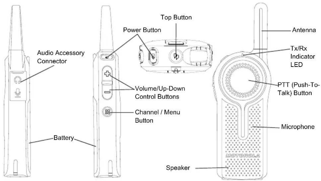
text_image
Audio Accessory Connector Battery Power Button Top Button Volume/Up-Down Control Buttons Channel / Menu Button Speaker Antenna Tx/Rx Indicator LED PTT (Push-To-Talk) Button Microphone MOTOROLAPower Button
Long press to turn the radio ON or OFF. Short press to check battery status.
Top Button
The radio Top Button comes defaulted to "Private Reply" feature.
Note: For more information regarding programming the Top Button to other features, refer to "Special Radio Call Features" on page 49.
Volume Control (+/-) Button
Used to increase (+), decrease (-) or mute the volume.
Audio Accessory Connector
Used to connect compatible audio accessories.
Microphone
Speak clearly into the microphone when sending a message.
Antenna
For models DLR1020 and DLR1060 the antennas are non-removable.
Tx/Rx Indicator LED
Used to indicate whether the radio is on standby, receiving or transmitting.
Push-to-Talk (PTT) Button
To talk, press the PTT (Push to Talk) and WAIT to hear the Talk Permit Tone (a quick double beep) BEFORE you start speaking. Hold the radio vertically 1 to 2 inches (2.5cm to 5cm) from mouth when talking. Release the PTT to listen.
Channel / Menu Button
In standard radio operation mode, the Channel/Menu button comes defaulted to channel function. To change channel, press the Channel / Menu button and then Press the (+) or (-) button to browse channels. Short press the PTT button to exit.
When in Advanced Configuration Mode, Channel / Menu button gives access and allows navigation to set up special features.
The Lithium-Ion (Li-Ion) Battery
DLR Series comes with a Standard Capacity
Li-Ion battery. Other batteries may be available. For more information, see “Battery Features” on page 12.
DLR Series Radio Specifications
The radio's model is shown on the back of the radio and provides the following information:
Table 1: DLR Series Radio Specifications
| Model | Frequency Band | Transmit Power (Watts) | Number of Channels | Antenna |
| DLR1020 ISM | 900 MHz 1 2 Non-removable | |||
| DLR1060 ISM | 900 MHz 1 6 Non-removable | |||
BATTERY FEATURES
DLR Series radios provide standard Lithium-Ion batteries.
Note: Batteries with different capacities and operational life may be available in future.
About the Li-Ion Battery
The DLR Series radio comes equipped with a rechargeable Li-Ion battery. This battery should be fully charged before initial use to ensure optimum capacity and performance.
Battery life is determined by several factors. Among the more critical are the regular overcharge of batteries and the average depth of discharge with each cycle. Typically, the greater the overcharge and the deeper the average discharge, the fewer cycles a battery will last. For example, a battery which is overcharged and discharged 100% several times a day, lasts fewer cycles than a battery that receives less of an overcharge and is discharged to 50% per day. Further, a battery which receives minimal overcharging and averages only 25% discharge, lasts even longer.
Motorola Solutions batteries are designed specifically to be used with a Motorola Solutions charger and vice versa. Charging in non-Motorola Solutions equipment may lead to battery damage and void the battery warranty. The battery should be at about 77°F (25°C) (room temperature), whenever possible. Charging a cold battery (below 50°F [10°C]) may result in leakage of electrolyte and ultimately in failure of the battery. Charging a hot battery (above 95°F [35°C]) results in reduced discharge capacity, affecting the performance of the radio. Motorola Solutions rapid-rate battery chargers contain a temperature-sensing circuit to ensure that batteries are charged within the temperature limits stated above.
Battery Recycling and Disposal
Li-Ion rechargeable batteries can be recycled. However, recycling facilities may not be available in all areas. Under various U.S. state laws and the laws of several other countries, batteries must be recycled and cannot be disposed of in landfills or incinerators. Contact your local waste management agency for specific requirements and information in your area. Motorola Solutions fully endorses and encourages the recycling of Li-Ion batteries. In the U.S. and Canada, Motorola Solutions participates in the nationwide Rechargeable Battery Recycling Corporation (RBRC) program for Li-Ion battery collection and recycling.
Many retailers and dealers participate in this program. For the location of the drop-off facility closest to you, access RBRC's Internet web site at:
www.rbrc.com
or call:
1-800-8-BATTERY
This internet site and telephone number also provides other useful information concerning recycling options for consumers, businesses and governmental agencies.
Installing the Lithium-Ion (Li-Ion) Battery
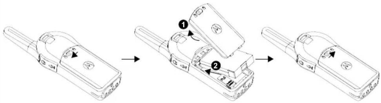
text_image
Diagram showing three-step assembly of a mobile phone device with labeled parts and directional arrows indicating motion.- Slide the latch at the top of the battery door to the unlock position and lift up the battery door at the center recess.
- Align the battery contacts with the tabs in the battery compartment. Insert the contact side of the battery first, then press the battery down to secure in place.
- Put the battery door back on the radio. Slide the latch to the lock position.
Removing the Lithium-Ion (Li-Ion) Battery
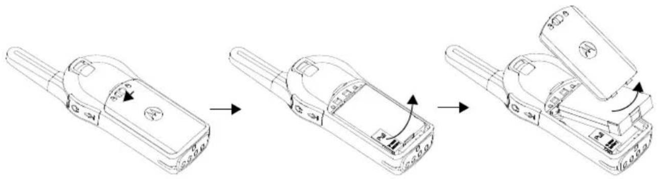
flowchart
graph LR
    A["Electricity Charger"] --> B["Battery with valve mechanism"]
    B --> C["Close-up of door panel with valve mechanism"]
    C --> D["Final Door Panel with valve mechanism"]
- Turn OFF the radio.
- Slide the latch at the top of battery door to the unlock position and lift up the battery door at the center recess.
- Pull on the battery removal tab until battery is disengaged from battery compartment.
- Pull the battery away from radio.
Holster
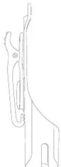
natural_image
Line drawing of a mechanical component or bracket (no text or symbols)- Insert the radio into the base of the holster at an angle. Press the radio against the back of the holster until the hooks on the holster are inserted in the top recesses of the battery.
- To remove, using the top tab on the holster, detach the hooks of the holster from the top recesses of the battery. Slide the radio at an angle and remove from the holster.
Power Supply, Adaptor and DLR Single Unit Charger (SUC) Tray
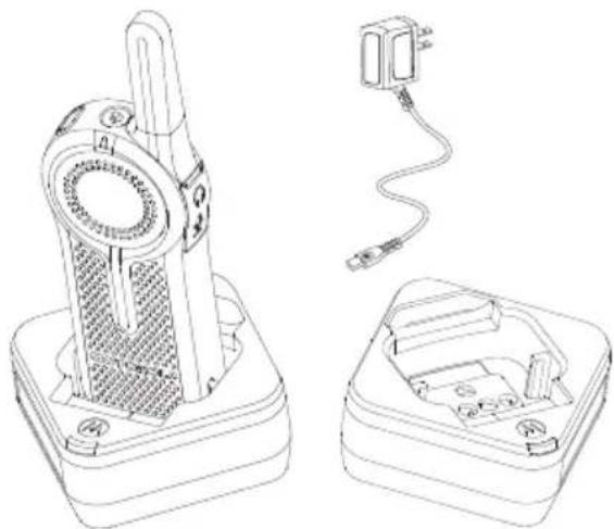
natural_image
Technical line drawing of a device with a cylindrical component and two open enclosures, no text or symbols present.The radio is equipped with one DLR Single Unit Charger (SUC) Tray and one Power Supply with Adaptor. See "Chargers" on page 113 for more information.
Battery Life Information
When the Battery Save feature is set to ON (enabled by default), the battery life lasts longer. The following table summarizes battery life estimations:
Table 2: Li-Ion Battery Life for DLR1020 and DLR1060
| Battery Type Battery Save OFF Battery Save ON | ||
| Standard 10.0 – 12.0 Hours | Up to 14 Hours | |
Note: Battery life is estimated based on 5% transmit / 5% receive / 90% standby standard duty cycle.
Battery Status Information
To check battery status, short press the Power button. DLR radio also announces battery level every time it powers up.
Table 3: Battery Status Information
| Battery Status Battery Level Voice Prompt or Tone | ||
| Battery High 100% – 71% | “Battery level high” | |
| Battery Medium 70% – 41% | “Battery level medium” | |
| Battery Low | 40% – 11% | “Battery level low” |
| Battery Critical | 10% – 0% | “Battery level critical” |
| Battery Shutdown | 0% | Shutdown beeps |
Note: Battery save is ON by default.
ATTENTION!
Always turn off the radios prior to charging. Radios charge the best of room temperature.
Charging with the Drop-in Tray Single Unit Charger (SUC)
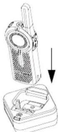
natural_image
Technical illustration of a handheld device with a downward arrow indicating a component (no text or symbols present)The DLR Series radio comes with a Standard Power Supply and DLR SUC tray.
- Place the DLR SUC tray on a flat surface.
-
Insert the connector of the power supply into the port on the side of the DLR SUC tray.
-
Plug the AC adaptor into a power outlet.
- Turn the radio "OFF".
- Insert the radio into the tray with the front of the radio facing the front of the charger, as shown. Make sure the radio is securely inserted all the way into the charger and the RED LED illuminates to indicate that the battery is charging. See "DLR Series Charger LED Indicators" on page 21 for more information.
Note: When charging a battery attached to the radio, turn the radio OFF to ensure a full charge. See "Operational Safety Guidelines" on page 8 for more information.
Charging A Stand-Alone Battery
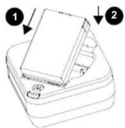
text_image
Diagram showing two stacked books with numbered labels pointing to each book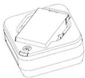
natural_image
Line drawing of a closed book with a stack of books and a bookmark (no text or symbols)English
To charge a battery, insert the battery into the charger's pocket by:
- Aligning the raised tab on each side of the battery with the corresponding groove on each side of the charger pocket.
- Pressing the battery toward the rear of the pocket.
- Sliding the battery into the charger pocket, ensuring complete contact between the charger and battery contacts.
- When the battery is properly seated in the pocket, the charger indicates the Battery Level status as shown in Table 6. The RED LED illuminates to indicate that the battery is charging rapidly.
- The LED changes to a STEADY GREEN light to indicate that the battery is nearly or fully charged.
Table 4: Motorola Solutions Authorized Batteries
| Part Number Description | |
| HKNN4013_Li-Ion | Battery 1800mAh |
Estimated Charging Time
The following table provides the estimated charging time of the battery. For more information, see “Battery” on page 113.
Table 5: Battery Estimated Charging Time
| Charging Solutions | Estimated Charging Time |
| Standard Battery | |
| Standard ≤ 3.50 Hours |
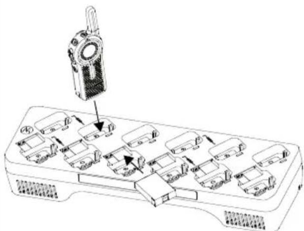
Charging a Radio and Battery using a DLR 12-Pocket Multi Unit-Charger - MUC (Optional Accessory)
text_image
Diagram of a device with labeled components and directional arrows indicating movement or assembly.The DLR 12-Pocket Multi-Unit Charger (MUC) allows drop-in charging of up to 12 radios or up to 6 radios and 6 stand-alone batteries.
Batteries can be charged with the radios or removed and placed in the MUC separately.
Each of the 12 charging pockets can hold a
radio (with or without the Holster) or battery, but not both.
- Place the Multi-Unit Charger on a flat surface.
- Insert the power cord plug into the MUC's dual pin connector at the bottom of the MUC.
- Plug the power cord into an AC outlet.
- Turn the radio OFF.
- Insert the radio or battery into the charging pocket with the radio or battery facing away from the contacts.
Note:
- This Multi-Unit Charger clones up to 2 radios (2 Source radios and 2 Target radios). Refer to "Cloning with a Multi-Unit Charger (MUC) (Optional Accessory)" on page 97 for more information.
- More information on the Multi-Unit Charger operation is available in the Instruction Sheets provided with the MUC. For more information on the parts and their part numbers, refer to Chapter "Accessories" on page 113.
DLR Series Charger LED Indicators
Table 6: Charger LED Indicator
| Status LED Status Comments | ||
| Power On | Green for approx. 1 sec  | |
| Charging | Steady red [5407] | |
| Charged | Steady green [2XW7] | |
| Error (*) | Red fast flash [2682] | |
| Standby (**) | Amber slow flash [K224] | |
| Battery Level Status | Flash red 1 time  | Battery low |
| Flash amber 2 times [2XWH] | Battery medium | |
| Flash green 3 times [STCH] | Battery high |
(*) Normally, re-positioning the battery pack will correct this issue.
(**) Battery temperature is too warm or too cold or wrong power voltage is being used.
If there is NO LED indication:
- Check that the radio, or stand-alone battery, is inserted correctly.
- Ensure the power supply is plugged into an appropriate AC outlet. (for DLR Single Unit Charger (SUC) Tray only).
- Ensure the cable is plugged securely into the charger socket (for DLR Single Unit Charger (SUC) Tray only).
- Ensure the power cord is plugged securely into the charger socket with an appropriate AC outlet and there is power to the outlet (for DLR 12-Pocket Multi Unit Charger Tray only)
- Confirm that the battery used with the radio is Motorola Solutions authorized batteries listed in Table 4.
DLR Radios and Charger Compatibility
Table 7: DLR and CLS Chargers Compatibility
| Chargers | Charging Compatibility | |||
| DLR radio with inserted battery | DLR standalone batteries | CLS radio with inserted battery | CLS standalone batteries | |
| DLR SUC | √ | √ | √ | |
| DLR MUC | √ | √ | √ | |
| CLS SUC | √ | × | √ | |
| CLS MUC | √ | × | √ | |
Note: Although DLR Series and CLS Series chargers are compatible, DLR and CLS radios operate in different frequency bands and will not communicate with each other.
Notes
English
GETTING STARTED
For the following explanations, refer to "Parts Of The Radio" on page 9.
text_image
Top Button Press the Top Button to queue up for Private Reply (while someone is talking in your channel). Press PTT button to Reply Privately to that last person who spoke. PTT (Push-To-Talk) Button Push PTT button firmly. Wait for TPT Tone. Talk into Microphone(*) (*)Ensure microphone is posi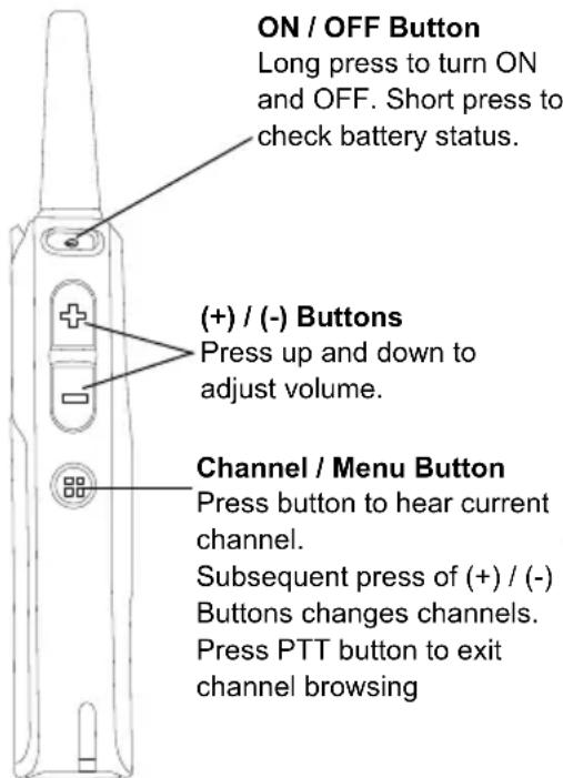
text_image
ON / OFF Button Long press to turn ON and OFF. Short press to check battery status. (+)/(-) Buttons Press up and down to adjust volume. Channel / Menu Button Press button to hear current channel. Subsequent press of (+)/(-) Buttons changes channels. Press PTT button to exit channel browsing.(*)Ensure microphone is positioned 1 to 2 inches (2.5 to 5 cm) away from mouth
To turn ON the radio, press and hold the Power button until the radio plays the power up tone and the standby light begins to blink.
Note: By default, when radio is turned ON, it announces the current channel name and battery status.
To turn the radio OFF, press and hold the Power button (\~3 seconds) until the radio Tx/Rx Indicator LED turns OFF and power down tone is heard.
ADJUSTING VOLUME
Press the (+) button to increase the volume, or the (-) button to decrease the volume.
To mute, press and hold the (-) button (\~2 seconds) until you hear the voice announcement "Mute".
Note: Radio mute means setting the volume to the lowest level. (This is to prevent the user from forgetting to unmute the radio.)
To maximize volume, press and hold the (+) button (\~2 seconds). The volume will fast scroll
up to maximum volume. You will hear the volume beeps increment as the volume increases.
Notes: Do not hold the radio too close to the ear when the volume is high or when adjusting the volume.
There are 16 increments of volume. As the (+) / (-) buttons are pressed, you will hear a beep at the current volume level. If device is receiving during volume interaction, received audio will be heard at the new volume instead of beeps.
When using radio with earpiece, make sure to adjust the radio volume to the lowest volume before putting on the earpiece. Refer to "Acoustic Safety" on page 3. Use only Motorola Solutions approved accessories. Refer to "Audio Accessories" on page 113 for more information.
CHECKING BATTERY STATUS
To check the battery status, short press the power button. Refer to "Battery Status Information" on page 17 for more information.
Note: The four levels available for battery status are : High, Medium, Low and Critical.
TRANSMITTING AND RECEIVING
• To receive, listen through the speaker.
- To respond or to talk, press the PTT (Push to Talk) and WAIT to hear the Talk Permit Tone (TPT) BEFORE you start speaking. Hold the radio vertically 1 to 2 inches (2.5cm to 5cm) from mouth when talking. Release the PTT to listen.
- The Tx/Rx Indicator blinks slowly RED when on standby. When the radio is transmitting, the Tx/Rx Indicator is solid RED.
- When the radio is receiving, the Tx/Rx Indicator LED blinks RED quickly.
IMPORTANT: When talking on the radio, make sure not to release the PTT button at any given time. Whether you are transmitting using the PTT button or
using an in-line PTT on the earpiece accessory, always ensure the PTT button is pressed firmly until the transmission is finished. Releasing the PTT button while transmitting and trying to immediately press the PTT button again causes the radio to give a loud denial tone. Wait for 2 seconds and press PTT again to continue speaking. If you press the PTT button to transmit and a busy tone is received instead of a TPT, this means the channel is either not available, busy or there are no users reachable within transmission range.
Talk Permit Tone (TPT)
TPT is a quick distinctive double beep tone that sounds after the user presses the PTT button, indicating the channel is free to talk. TPT is useful in ensuring orderly communications by preventing radios from transmitting over ongoing conversations.
Always wait to hear the TPT before starting to speak to ensure your words are not cut off.
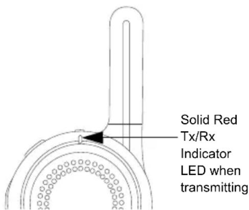
text_image
Solid Red Tx/Rx Indicator LED when transmittingTalking to a Group in a Channel
To transmit, press the PTT (Push to Talk) and WAIT to hear the TPT (Talk Permit Tone) BEFORE you start speaking.
BROWSING / SELECTING A CHANNEL
To select a channel, press the Channel / Menu button until the voice announcement "Channel
Press (+) or (-) buttons to select the desired channel. An audible voice indicates the selected channel.
To exit Channel Change, press the PTT button or wait for the radio Channel / Menu timer to expire.
PRIVATE REPLY
DLR radio comes with the Top Button configured to Private Reply Feature i.e. when you hear someone talking on the radio, push the Top Button to queue for Private Reply function (Top Button LED indicator blinks orange). Once the person finishes talking, press the PTT button to Reply Privately to that person (Top Button LED illuminates solid orange). Voice prompts and tones will guide you on Private call status. For more details on how to use this feature, refer to “Special Radio Call Features” on page 49.
TOP BUTTON OPTIONS
The Top Button comes pre-programmed with the Private Reply Feature. Top Button can be configured also to allow other different call features such as: Page All Available, Call
Available, Direct Call and Mute. It can also be disabled. For more details on how to configure the Top Button refer to "Advanced Configuration Mode" on page 33.
TALK RANGE
| TALK RANGE | ||
| Model | Industrial Multi-Level | |
| Inside steel/concrete Industrial buildings | Inside multi-level buildings | |
| ISM900 MHz | Up to 300,000 Sq. Ft. | Up to 20 Floors |
For a group of DLR radios to be able to communicate, they need to be on the same channel and have the same radio PROFILE ID number. All radios come by default programmed to PROFILE ID number "0000"
-
Channel: Current channel that the radio is using, depending on radio model.
-
PROFILE ID Number: ALL the radios in your fleet (independent of the channels that users are assigned to) should use the SAME PROFILE ID. It is also VERY IMPORTANT TO CUSTOMIZE THE PROFILE ID number in order to avoid interference from other users using the default "0000" number. In order to customize your radio fleet PROFILE ID, choose a 4 digit number and enter it using the radio Advanced Configuration Mode (Turn off the radio, Press the PTT, (+) and Power buttons simultaneously and hold until radio announces "Programming Mode". Follow voice prompts). For more information, refer to the "Advanced Configuration Mode" on page 33.
DLR AND DTR RADIOS COMPATIBILITY
DLR and DTR radios are based on the same digital radio technology and can be used in mixed fleets of DLR and DTR radios. Out of the box, DLR and DTR radios will communicate using the factory default settings.
If you have DTR radios with customized settings and/or private groups, and need to add DLR radios, make sure to use the DLR CPS software(*) in order to create a compatible configuration in the DLR radios. The same applies if DTR radios are to be added to an existing DLR radio fleet. For more details on DTR and DLR compatibility please contact your Motorola Solutions point of sale.
For questions or comments related to this product, please contact Motorola Solutions: 1-800-448-6866
Note: (*) DLR CPS software is available for free download at www.motorolasolutions.com/DLR
RADIO STATUS
| Radio Status Front LED Indicator Top Button LED Indicator | Voice Prompt or Tone | ||
| Power Up Solid Red for 2 seconds OFF | “Battery Level,, Channel” | ||
| Power Off | Solid Red for 2 seconds | OFF | Power Off chirps |
| Fatal Error at Power up | Double Blink Red | Single Blink Orange | Not Available |
| Channel Busy | Not Available | OFF | Busy tone |
| ‘Idle’ Mode | Heartbeat Red | OFF | Not Available |
| Transmit (Tx) (standard group call) | Solid Red | OFF Not Available | |
| Receive (RX) (standard group call) | Fast Red Heartbeat | OFF | Not Available |
Notes
English
The DLR Advanced Configuration Mode allows you to configure special settings in your radio without the need of programming cables or additional software.
Advanced Configuration Mode gives access to customize the following features:
- PROFILE ID Number,
• Maximum Channels, - Top Button,
- Microphone (MIC) Gain, and
- Home Channel.
Table 1: Advanced Configuration Mode Features
| Feature Description | |
| PROFILE ID Number | Choose a 4 digit number (0000 – 9999) as your radio PROFILE ID Number. Customize the PROFILE ID Number to ensure interference free / private communications. |
| Maximum Channels | Choose the maximum number of channels you want to allow for your radio. |
| Top Button | Set the Top Button with one of the following feature: Private Reply, Direct Call(*), Call All Available, Page All Available, Mute, Disabled. |
| MIC Gain | Choose between High, Medium or Low MIC Gain to adjust the radio microphone sensitivity level to fit different users or noise environments. |
| Home Channel | Choose the channel you want to designate as your main channel. Everytime you change to a different channel and no activity is detected from the channel, the radio reverts back to your home channel. |
(*) Only if enabled via CPS
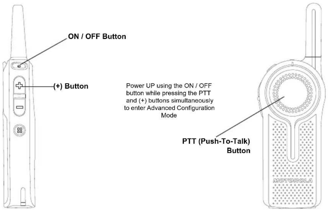
ENTERING ADVANCED CONFIGURATION MODE
To enter the Advanced Configuration Mode, power UP using the ON / OFF button while pressing the PTT and (+) buttons simultaneously.
text_image
ON / OFF Button (+) Button Power UP using the ON / OFF button while pressing the PTT and (+) buttons simultaneously to enter Advanced Configuration Mode PTT (Push-To-Talk) Button MOTOROLAEnglish
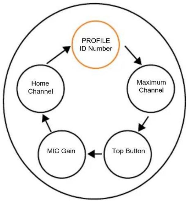
BROWSING ADVANCED CONFIGURATION OPTIONS
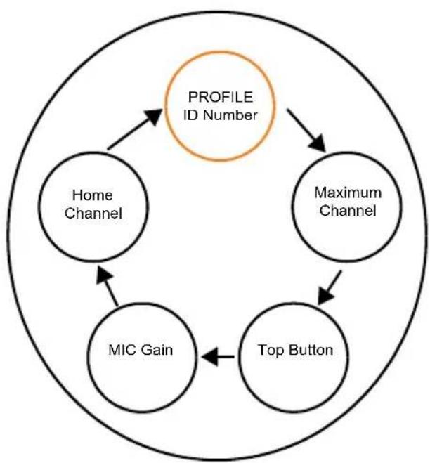
Upon entering Advanced Configuration Mode, radio plays voice prompt "Programming Mode. Press Menu to continue". Press Channel / Menu button to cycle through the Advanced Configuration options.
Note: Long press the PTT button at any time to exit the Advanced Configuration Mode altogether.
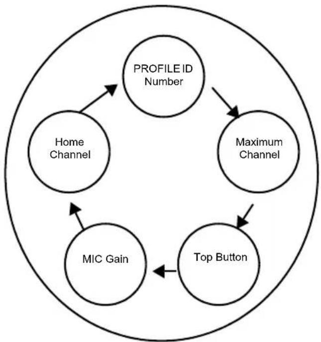
flowchart
graph TD
    A["PROFILE ID Number"] --> B["Maximum Channel"]
    B --> C["Top Button"]
    C --> D["MIC Gain"]
    D --> E["Home Channel"]
    E --> A
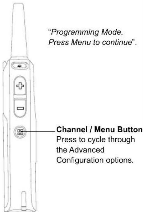
text_image
"Programming Mode. Press Menu to continue". Channel / Menu Button Press to cycle through the Advanced Configuration options.PROFILE ID Number
PROFILE ID Number – Current Value
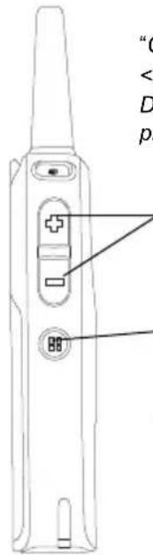
Once you press the Channel / Menu button, the radio announces the current PROFILE ID Number(*) and prompts you to change it. Press (+) or (-) button to enter the PROFILE ID Number sub-menu. Alternatively, press the Channel / Menu button to continue to the next Advanced Configuration option.
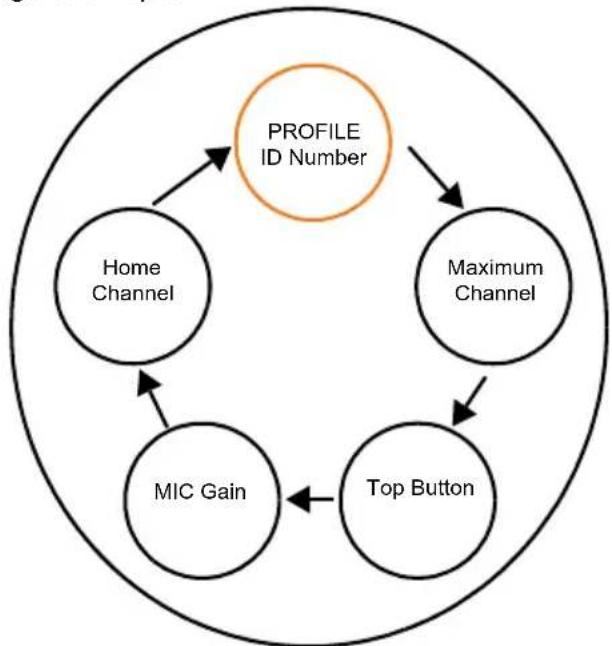
flowchart
graph TD
    A["Profile ID Number"] --> B["Home Channel"]
    A --> C["Maximum Channel"]
    A --> D["MIC Gain"]
    A --> E["Top Button"]
    B --> A
    C --> A
    D --> A
    E --> A
text_image
"C < D p(+) / (-) Buttons Press to enter the PROFILE ID Number sub-menu Channel / Menu Button Press to continue to the next Advanced Configuration option
(*) PROFILE ID Number default is "0000". Change it to avoid interferences and improve privacy.
PROFILE ID Number – Changing values
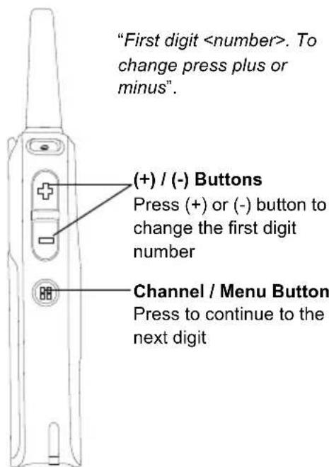
Once you press either the (+) or (-) to enter the PROFILE ID Number sub-menu, the radio announces the first digit number value and prompts you to change it(*). Press (+) or (-) button again to change the first digit number. Press Channel / Menu button to continue to the next digit.
flowchart
graph TD
    A["Profile ID Number"] --> B["Home Channel"]
    A --> C["Maximum Channel"]
    A --> D["Top Button"]
    A --> E["MIC Gain"]
    B --> E
    C --> E
    D --> E
text_image
"First digit(*) There is 10,000 options of PROFILE ID Number to choose from (0000 - 9999).
PROFILE ID Number – Sub-menu
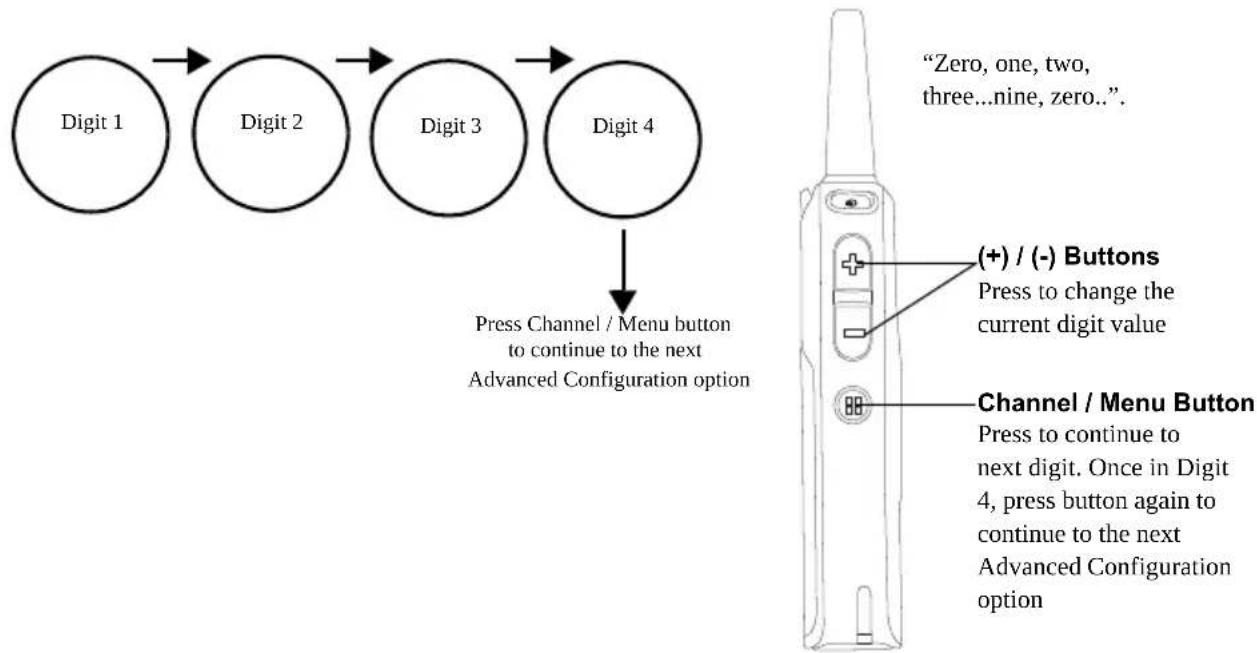
When you press (+) or (-) button to change the current digit, radio announces the value. Press Channel / Menu to continue to the next digit. Once in Digit 4, press Channel / Menu button again to continue to the next Advanced Configuration option.
Note: DLR radio gives you the option to move forward through the 4 digits with the Channel / Menu button. There is no option to move backward through the 4 digits of PROFILE ID Number.
flowchart
graph TD
    A["Digit 1"] --> B["Digit 2"]
    B --> C["Digit 3"]
    C --> D["Digit 4"]
    D --> E["Press Channel / Menu button to continue to the next Advanced Configuration option"]
    E --> F["Zero, one, two, three...nine, zero..."]

    G["Channel / Menu Button"] --> H["Press to continue to next digit. Once in Digit 4, press button again to continue to the next Advanced Configuration option"]
    I["(+)/(-) Buttons"] --> J["Press to change the current digit value"]
PROFILE ID Number – Value Modification Confirmation
Once you have set the 4 digit PROFILE ID Number, the radio announces the entire new PROFILE ID Number value. Press Channel / Menu button to continue to the next Advanced Configuration option or hold down the PTT button to exit the Advanced Configuration Mode.
Note: If the 4 digit PROFILE ID number set is not the numbers wanted upon moving to the next Advanced Configuration option, press the Channel / Menu button and cycle through the Advanced Configuration options until you are back at the PROFILE ID Number option to change the value.
flowchart
graph TD
    A["Profile ID Number"] --> B["Home Channel"]
    A --> C["Maximum Channel"]
    A --> D["Top Button"]
    A --> E["MIC Gain"]
    B --> A
    C --> A
    D --> A
    E --> A