992002FBN - Lighting Hinkley Lighting - Free user manual and instructions
Find the device manual for free 992002FBN Hinkley Lighting in PDF.


User questions about 992002FBN Hinkley Lighting
0 question about this device. Answer the ones you know or ask your own.
Ask a new question about this device
Download the instructions for your Lighting in PDF format for free! Find your manual 992002FBN - Hinkley Lighting and take your electronic device back in hand. On this page are published all the documents necessary for the use of your device. 992002FBN by Hinkley Lighting.
USER MANUAL 992002FBN Hinkley Lighting
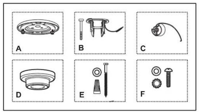
A. Mounting plate
B. Hanger bracket with 3 / 16"× 65mm Safety pin
C. Hanger ball
D. Canopy
E. #12 x 3" Wood screws (2 pcs), Wire nuts (3 pcs), Washers (2 pcs),
F. #8-32W X 1" Mounting screws pcs, washer (2 pcs), star washer (2 pcs)
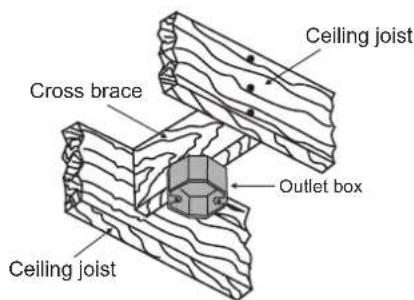
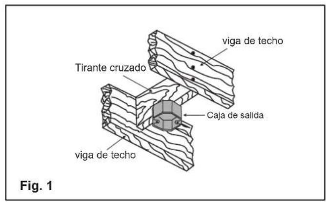
Fig. 1
MOUNTING OPTIONS
Make sure the outlet box you've selected for mounting your ceiling fan is UL listed and rated for ceiling fan use.
NOTE: Make sure the electrical power is turned off before starting. Disconnect at the main circuit box.
Secure the outlet box directly to the building structure. Use appropriate fasteners and building materials. The outlet box and its support must be able to fully support the moving weight of the fan (at least 35 lbs). Do not use plastic outlet boxes.
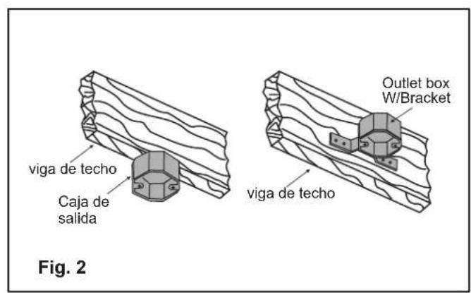
Figures 1 and 2 are examples of different ways to mount the outlet box.
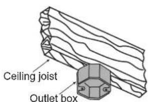
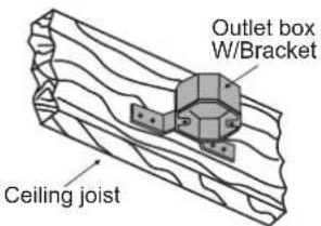
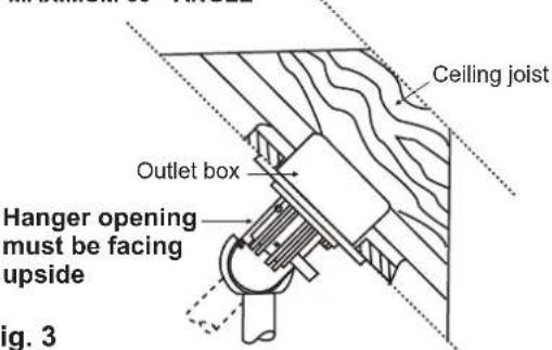
Fig. 2
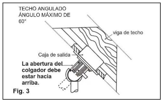
ANGLED CEILING
MAXIMUM 60° ANGLE
Fig. 3
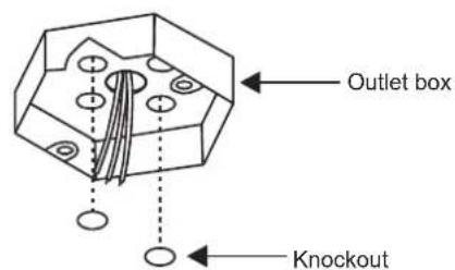
Fig. 4
A. INSTALLING THE MOUNTING PLATE TO A OUTLET BOX (MOUNTED DIRECTLY TO A CEILING JOIST)
- Remove two knock-outs from the outlet box to expose the joist. (Fig. 4)
- Use the two # 12× 3'' wood screws and washers to secure the mounting plate directly to the building joist via the knockout holes from the outlet box. (Fig. 5)
- Use the mounting plate as a guide to mark the hole position in the joist.
- Predrill the holes using a 5/32" drill bit.
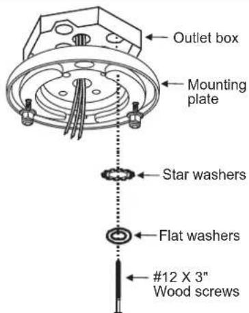
Fig. 5
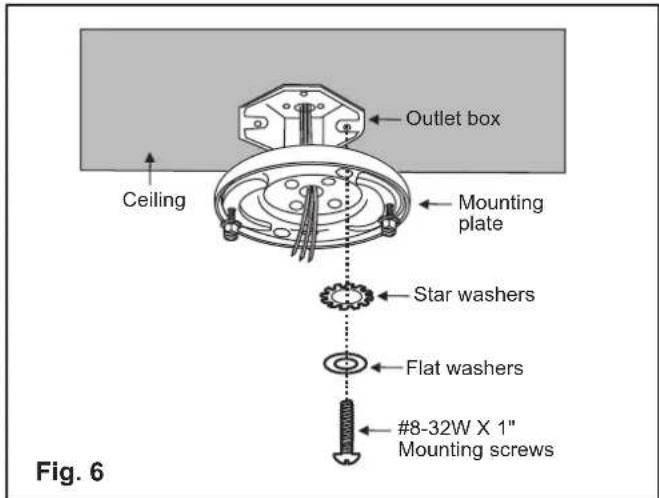
B. INSTALLING THE MOUNTING PLATE DIRECTLY TO AN OUTLET BOX
The outlet box and support structure must be securely mounted and capable of reliably supporting a minimum of 35 lb (15.9 kg) or less. Use only UL-Listed outlet boxes marked "FOR FAN SUPPORT." (Fig. 6)
WARNING: To reduce the risk of fire, electric shock or personal injury, mount the fan to the outlet box marked acceptable for fan support with the screws provided with the outlet box.
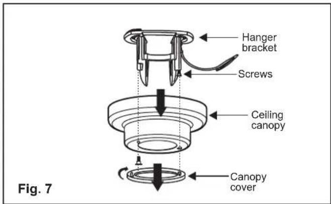
INSTALLING THE HANGING BRACKET TO MOUNTING PLATE ASSEMBLY
- Remove the canopy cover from the canopy by turning the cover counter clockwise. Remove the hanger bracket from the canopy by removing the 1 of 2 screws from the bottom of the hanger bracket and loosening the other one a half turn from the screw head. This will enable you to remove the hanger bracket. (Fig. 7)
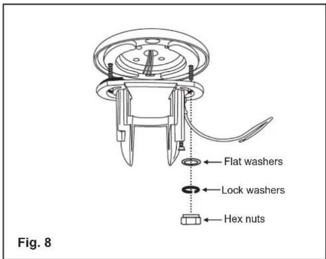
- Attach the hanger bracket to the mounting plate using the two hex nuts and washers and lock washers provided. (Fig. 8)
DO NOT tighten completely at this point. Allow hanger bracket to rotate but hold the weight of the ceiling fan.
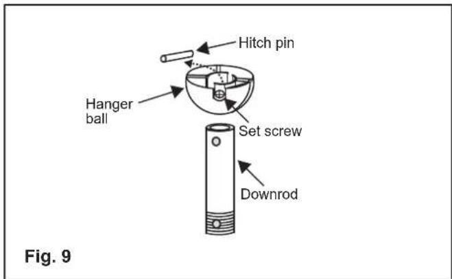
- If you plan to use the downrod packaged with your ceiling fan, remove the hanger ball by loosing the set screw, unscrewing the safety pin and unscrewing the hanger ball. If you are using a different downrod, skip to the next step. (Fig. 9)
-
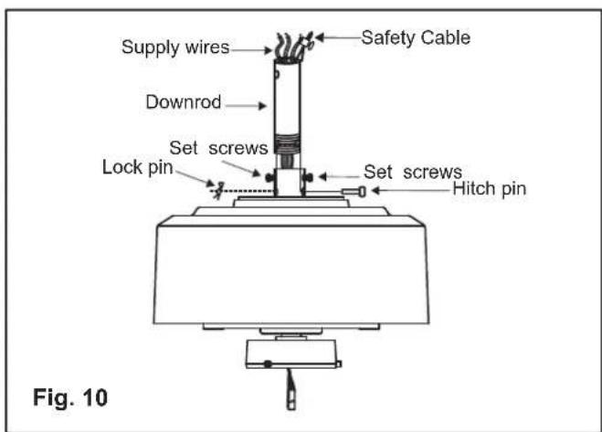
Loosen the two set screws in the motor coupling until the inside channel is clear of the screws. Remove the Safety Pin and Locking Clip in the top of the motor coupling. (Fig. 10)
-
Carefully feed the fan lead wires and safety cable up through the downrod. Thread the downrod into the motor coupling until the Safety Pin holes are aligned. (Fig. 9) Next, replace the Safety Pin and secure with the Locking Clip. Securely tighten both set screws. (Fig. 10)
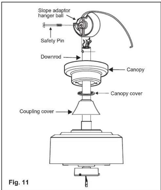
. Slip the coupling cover, mounting screw cover and canopy onto the downrod in the order shown. (Fig. 11)
- Thread the Slope Adaptor Hanger Ball onto the downrod until the Safety Pin center hole on the Ball aligns with the safety pin hole in the downrod. Insert the safety pin (careful not to damage the lead wires.) (Fig. 11)
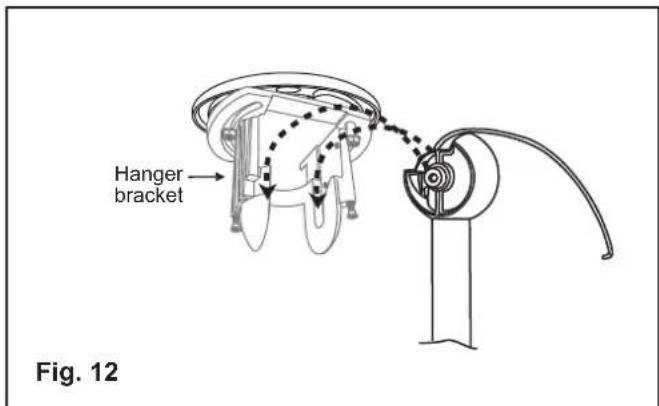
NOTE: The Hanger Ball can be installed in ONLY one direction. The "cutout" should be toward the "Lower" end of the ceiling slope. (Fig. 12)
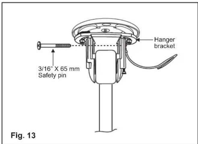
- Now lift the motor assembly into position with the hanger ball in the position (shown in Fig. 13) and place the pivot pens on the hanger ball into the pivot groves on the hanger bracket. (Fig 12)
Next, lower the hanger ball until the pivot pens rest in the bottom of the pivot groves. (Fig 12)
- Make sure the Safety Pen installed in Fig 12 is installed but NOT tightened. (Fig 13)
DO NOT TIGHTEN AT THIS TIME
FINISHING THE INSTALLATION
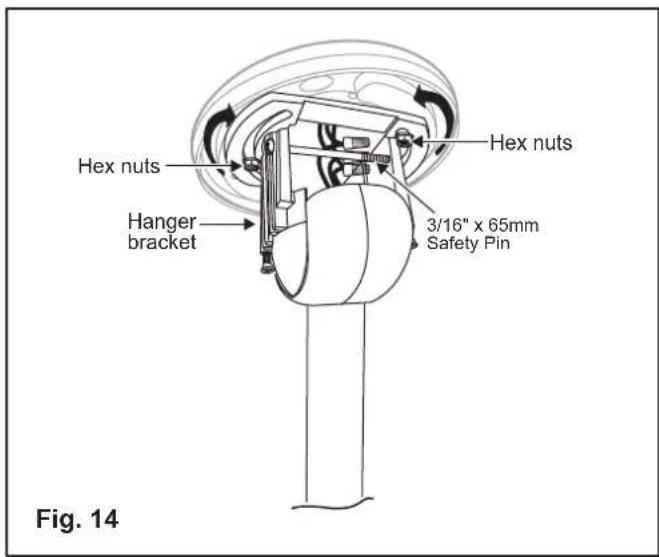
- Now, rotate the "entire fan and slope adaptor assembly" (left or right) by rotating the hanger bracket until the downrod and the ceiling fan assembly are hanging straight down and the entire assembly "swings" freely in the exact direction of the ceiling slope. (Fig. 14)
- Now, Securely tighten the two (2) Hex Nuts holding the hanger bracket to the mounting plate. Making sure the Hanger Bracket is secure and can not move. Next, securely tighten the 3/16" x 65mm Safety Pin. (Fig. 14)
- Make all necessary electrical connections by referring to your ceiling fan installation manual.
Next, tuck all lead wires neatly into the opening above the hanger ball.
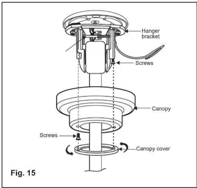
4. Slide the canopy up to the ceiling and place the mounting screws through the key holes in the face of the canopy. Rotate canopy clockwise. (Fig. 15)
Next, while holding the canopy with one hand, slide the mounting screw cover onto the heads of the mounting screws and rotate clockwise until tight.
If necessary, adjust the canopy screws until the canopy and mounting screw cover are snug.