
SCE275 - Ice Maker Scotsman - Free user manual and instructions
Find the device manual for free SCE275 Scotsman in PDF.
User questions about SCE275 Scotsman
0 question about this device. Answer the ones you know or ask your own.
Ask a new question about this device
Download the instructions for your Ice Maker in PDF format for free! Find your manual SCE275 - Scotsman and take your electronic device back in hand. On this page are published all the documents necessary for the use of your device. SCE275 by Scotsman.
USER MANUAL SCE275 Scotsman
natural_image
Line drawing of a laboratory appliance with lid, vent, and side legs (no text or symbols)English....Page 3
User Manual for the SCE275
Table of Contents
| Introduction. | page 3 |
| Warranty. | page 3 |
| Installation. | page 3 |
| Location & Assembly. | page 3 |
| Plumbing. | page 5 |
| Electrical. | page 5 |
| Final Check List. | page 6 |
| Initial Start Up. | page 6 |
| Removal of the Cabinet. | page 7 |
| Maintenance. | page 9 |
| Failure Analysis. | page 9 |
Introduction
This manual contains the information needed for the set up, installation, initial start up, sanitation and maintenance this product.
The SCE275 is an ice machine that produces cubed ice on a vertical freezing surface. The cubes fall into the ice storage bin where they break up into individual cubes. The ice machine automatically maintains the level of ice by switching on when the ice level falls, and switching off when the bin is full.
This unit is serviceable in place; the ice storage bin and hood may be removed from the chassis to allow service access without removing the ice machine from its installed position.
Warranty
The warranty conditions are those supplied by the official distributor for your area. In case of parts, only genuine service parts may be used.
Installation Limitations
The unit is equipped with an electrical power cord, but should only be plugged into a circuit dedicated to the ice machine.
The ice machine must be installed indoors in a controlled environment.
Minimum Maximum
| Air Temp 50 | ^0F.100 | ^0F. |
| Water Temp 40 | ^0F.100 | ^0F. |
Water Pressure 20 PSI 80 PSI
Voltage (50 Hz) 207 253
Operating the ice machine outside of the above limitations, or outdoors, is potentially damaging and is misuse of the machine. This may void the warranty.
Scotsman Ice Systems are designed and manufactured with the highest regard for safety and performance.
Scotsman assumes no liability or responsibility of any kind for products manufactured by Scotsman that have been altered in any way, including the use of any part and/or other components not specifically approved by Scotsman.
Scotsman reserves the right to make design changes and/or improvements at any time.
Specifications and design are subject to change without notice.
Location and Assembly
Airflow on air cooled models is: Intake through the left front grill. Exhaust through the right front grill.
Do not install where this air flow is obstructed.
The SCE275 has a removable cabinet. When installed, the machine should have some extra clearance (1/8") on the left and right sides so that the cabinet may be easily removed when the machine is in place.
Installation
This ice machine may be installed in the open or under a counter. No clearance is required at the sides or top beyond what's needed to place the cabinet into position. Air cooled models blow air in and out through the grills at the front. Space is required for utility connections at the back.
The ice machine is not designed for outdoor use. It must be installed indoors, in a controlled environment. The air and water temperatures must not exceed rated limits.
Electrical power is supplied through a cord connected to the unit. All local codes must be followed.
Pre-installation:
- Inspect the place where the ice machine is to be installed. Check for:
• space for the cabinet,
- water supply,
- drain availability
- and electrical power supply connection within reach of the machine's power cord.
No extension cords are allowed. The building drain inlet must be lower than the drain outlet(s) at the back of the ice machine. The water supply must have a hand shut off valve accessible when the unit is installed.
- Determine the method of installation, is the machine to be installed under the counter? Is the drain in the floor under the machine? Is the water inlet valve accessible?
Unpack and Assemble
- Remove legs and scoop from storage bin.
- Remove shipping materials from ice making area.
- Place corner posts from the shipping carton on the floor behind the ice machine. Tip the ice machine on its back and remove the shipping skid.
- Screw the legs into the threaded holes in the base of the ice machine.
- Tip the ice machine back to an upright position.
natural_image
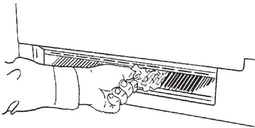
Line drawing of a hand holding a rectangular object with a textured surface (no text or symbols)Remove Material Located Between Cube Deflector and Troughs
For The Plumber
Begin by planning the installation and obtaining the needed supplies:
- 3/8" soft copper tubing
• 3/4" rigid drain tubing - 3/4" FPT fitting for bin/reservoir drain connection
• 1/2" FPT fitting for condenser drain connection -
3/8" FPT fitting for water cooled condenser inlet connection
-
Connect cold potable water to the 3/8" male flare at the back of the cabinet. A water filter and hand shut off valve is recommended. Flush the water line prior to connecting to the ice machine.
If water cooled, connect a separate water inlet line to the water cooled condenser inlet fitting. It should also have a hand shut off valve.
A loop of copper tubing may be used between the ice machine and the water supply. This will allow the ice machine to be pulled out from its installed location without disconnecting the water line.
- Connect a drain tube to each drain connection (water cooled drain must be separate).
- Route the drain tubes to the building drain receptacle.
For The Electrician
Connect 50 Hz models to the correct voltage and fuses. If the cord becomes damaged, the part number for a replacement is 12-1638-18.
The electrical disconnect switch with fuse protection must be a two pole type with a minimum of 3 mm between open contacts.
Follow All Local Codes - This Unit Must Be Grounded. Do not use extension cords and do not disable or by-pass ground prong on electrical plug.
After Utility Connections:
text_image
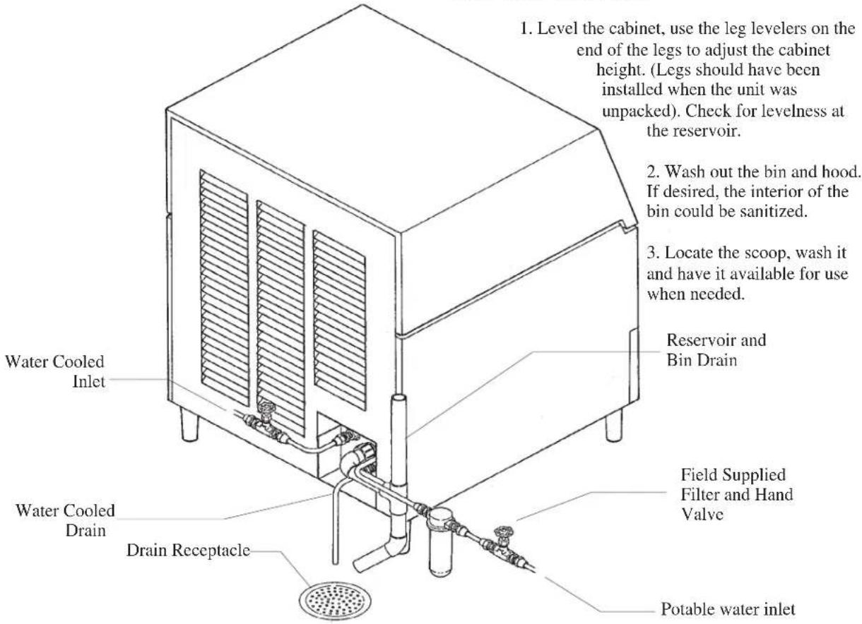
1. Level the cabinet, use the leg levelers on the end of the legs to adjust the cabinet height. (Legs should have been installed when the unit was unpacked). Check for levelness at the reservoir. 2. Wash out the bin and hood. If desired, the interior of the bin could be sanitized. 3. Locate the scoop, wash it and have it available for use when needed. Reservoir and Bin Drain Water Cooled Inlet Water Cooled Drain Drain Receptacle Field Supplied Filter and Hand Valve Potable water inletPlumbing Connections, Water Cooled Shown
Final Check List
- Is the ice maker cabinet in a room where ambient temperatures are within the minimum and maximum temperatures specified?
- Has the water supply been connected?
- Is the water pressure adequate?
- Have the water connections been checked for water leaks?
- Have the drain connections been made?
- Have the drain connections been checked for leaks?
- Is the cabinet level?
- Is the ice machine connected to an electrical power supply of the proper voltage and is the ice machine the only load on that circuit?
- Has all of the shipping material been removed from the inside of the cabinet? Check for materials between the cube deflector and the water troughs. Be sure the cube deflector is in place.
- Has the bin and cabinet been wiped clean and sanitized?
Initial Start Up
- Remove two screws and the right grill.
- Locate the AutoIQ Controller.
- Plug the machine in or switch on the electrical power. Note that the controller's indicator lights all flash on briefly when power is connected.
-
Open the water supply valve to the machine.
-
Push and release the Freeze cycle push button (the Freeze indicator light will blink until the compressor starts).
• The Freeze light begins to blink.
• The Hot Gas Solenoid valve will be open.
- The inlet water valve opens to fill the reservoir and shuts off when the reservoir is full. Note: If the reservoir does not fill the next steps do not happen.
- The water pump starts. Note: if the pump does not start the next steps do not happen.
- The inlet water valve opens again to refill the reservoir.
- After 30 seconds, the hot gas valve closes and the compressor starts.
Freeze Cycle:
The Freeze indicator light will come on. The machine will stay in a Freeze cycle for many minutes. Slush may appear in the reservoir, it is temporary and normal.
Under certain conditions, the pump may stop for a few seconds. After that the inlet water valve will refill the reservoir.
The fan motors (of air cooled models) will begin to turn and soon warm air will be forced out the front of the cabinet. After 4 minutes the fan motors may cycle on and off every 30 seconds in cooler ambients.
As the freeze cycle progresses, the water level will fall and the inlet water valve will open to refill the reservoir. This will happen twice every cycle.
The freeze cycle will continue until the water level in the reservoir has fallen again to its factory set point, then the AutoIQ Controller may switch the air cooled fan off. After a short time, the Harvest Cycle will begin.
Harvest Cycle:
• The Harvest indicator light will be ON,
• The hot gas valve will open.
- The water pump will stop. It will restart in less than a minute.
- The Inlet water valve will open. The machine will fill the reservoir and overflow it for a specified number of seconds then shut off. The harvest cycle may still be in progress.
- The Bin Full indicator light will go on and off as ice falls from the evaporators.
-
Observe ice harvest. Check that the ice slides easily into the bin, and does not hang up on any mis-positioned part.
-
After about 5 minutes the machine will return to a freeze cycle.
Note: The first 1-2 harvest cycles will be very long to establish a typical harvest time.
-
Replace the front grill.
-
Inform the user of the location and telephone number of the local service company. Also inform the user of the required maintenance of the machine.
Notes on Operation
-
The unit will shut off when ice has filled up the bin and collected on the ice deflector.
-
If the ice machine has just shut off with the bin full of ice and ice is immediately removed, the machine will delay its restart for 4 minutes.
Removal of the Cabinet
One of the most useful features of this ice machine is the ability to remove the cabinet from the ice machine without removing the ice machine from its installed position.
To remove the cabinet base the hood must be removed first.
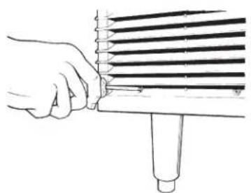
- Remove 5 screws and the three grills at the front of
natural_image
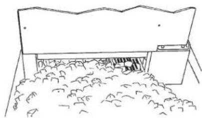
Simple line drawing of a mechanical component with a base and clamped parts (no text or symbols)When the machine fills up to its shut off point, ice will be on the cube deflector.
the base.
-
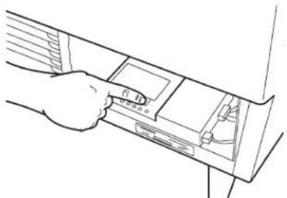
Push and hold the Off button the AutoIQ Controller until the machine has switched OFF. Be certain the ice machine has been switched off.
-
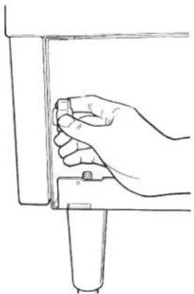
Open the bin door and unscrew the knobs at the left and right inside of the ice storage bin. Unscrew the knobs all the way out.
-
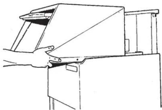
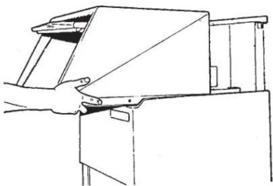
Pull the hood and door assembly straight out until it can be lifted up.
natural_image
Hand holding a tool interacting with a rack of parallel strips (no text or symbols visible)- In the area behind the grills (removed in step 1) are two knobs similar to those removed in step 3. Unscrew and remove the two knobs.
natural_image
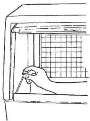
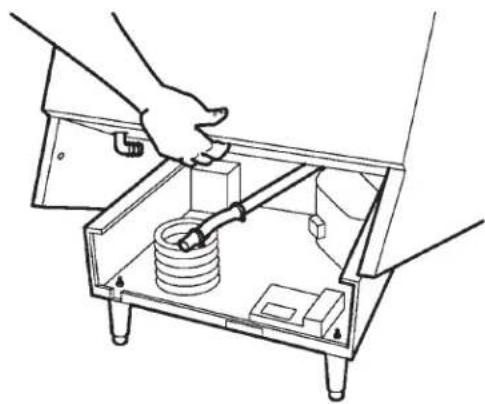
Line drawing of a hand inserting a device into a folder (no text or symbols)- Locate the bin drain. Loosen the hose clamp holding the drain tube to its fitting and pull the drain tube off of the fitting.
natural_image
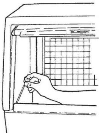
Line drawing of a hand holding a tool near a window with a grid pattern (no text or symbols)- Lift up the front of the base and rotate the base up and off of the ice machine.
natural_image
Line drawing of a hand operating a mechanical device with a handle (no text or symbols)The machine is now exposed for service.
How to Operate the Controller
natural_image
Line drawing of a hand holding a small object near a vertical panel (no text or symbols)The controller is a microprocessor device that receives input from several sources and switches various components on and off.
Its manual control is through the use of the push button switches.
natural_image
Line drawing of a hand using a tool to adjust or install a mechanical component inside a transparent box (no text or symbols)Freeze Button: Pushing and releasing this button starts or restarts the machine.
Harvest Button: Pushing and releasing this button will cause the machine to go directly to a Harvest Cycle. Can be done from either Freeze or Off. The machine will switch off at the end of the Harvest Cycle.
Clean Button: Pushing and releasing this button will cause the machine to go into a clean cycle. After the ice machine cleaner has circulated for about 10 minutes, a second push of this button will start the rinse period.
Off Button: Pushing and releasing this button will switch the machine off a the end of the next cycle. If the button is pushed and held for more than 3 seconds the unit will switch off immediately.
To reset: First push and release the off button, then push and release the freeze button.
Cleaning Schedule:
Scrub the door and frame edges once a week with soap and water.
Sanitize the bin interior once a month.
Clean the water system and air cooled condenser a minimum of twice per year. If in an area of high mineral concentration in the water supply, clean water system 4 times a year.
This ice machine will perform at its best when kept clean. There are three areas to keep clean: The water system including the water reservoir, distributors and evaporator surface; the bin controls; and the air cooled condenser filter and the condenser itself.
Air Filter (air cooled only):
The air filter is located in a slot between the condenser fins and the condenser fans.
-
Remove the grill on the left front of the unit.
-
Locate the filter edge, it is between the condenser fins and the fan motors.
-
Pull the filter to the left though the slot in the front base of the ice machine.
-
Wash the surface of the filter off with cold water, or, if torn or so dirty it can't be cleaned, replace with a new filter.
-
Return the filter to its installed position.
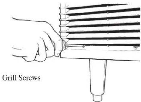
text_image
Grill ScrewsGrill Removal
- Replace the grill. Do not operate the unit without the filter in place.
Note: If the unit has been operated without the filter in place, the fins of the condenser will become fouled with
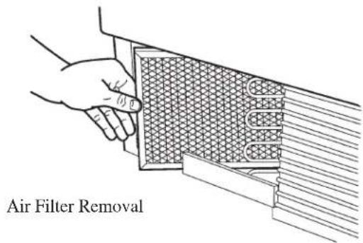
text_image
Air Filter Removaldirt, and must be cleaned.
If there is any doubt about dirt inside the fins of the condenser, the cabinet should be removed and a qualified service agent should clean the condenser.
Cleaning of the Ice Machine Water System:
This is critical to the proper operation of the ice machine. Call the authorized Service Agent at least twice per year to perform this service.
Additional Maintenance
The storage bin must be cleaned regularly to maintain a sanitary environment. Once a week cleaning of the door and door frame with soap and water, a hot water rinse and an air dry is a basic procedure.
Exterior Cabinet Cleaning:
The exterior cabinet may be cleaned by scrubbing with soap and water. Do not use cleaners containing petroleum products.
A nylon type brush may be used to scrub stubborn deposits.
Failure Analysis
(What to do before calling for service)
If the machine does not work:
Is the power on?
Is the water supply on?
Are the water filters plugged up?
If the machine does not make enough ice:
Are the air and water temperatures too high?
Is the air filter in the machine dirty?
If the machine makes the incorrect shape ice cubes:
Has the machine received its twice per year water system cleaning?
Register installations in North America, the Caribbean, Central or South America by mailing the yellow registration form to:
Scotsman Ice Systems
775 Corporate Woods Parkway
Vernon Hills, IL 60061
USA
Telephone 847-215-4500
Fax: 847-913-9844
Register installations in all other areas by mailing the card at the back of this manual to:
Scotsman Europe
Via Puccini, 22
Telephone 39-02-93960.1
Fax: 39-02-93550500
natural_image
Line drawing of a hand holding a tool near a mechanical component (no text or symbols)natural_image
Hand holding a tool interacting with a multi-layered rack or ticker (no text or symbols visible)natural_image
Line drawing of a hand inserting a device into a folder (no text or symbols visible)natural_image
Line drawing of a hand holding a tool near a window with a grid pattern (no text or symbols)natural_image
Line drawing of a hand operating a mechanical device with a handle (no text or symbols)natural_image
Line drawing of a hand holding a small object near a vertical panel (no text or symbols)natural_image
Line drawing of hands operating a mechanical device with a spring and base components (no text or symbols)775 Corporate Woods Parkway
Vernon Hills, IL 60061
USA
Téléphone 847-215-4500
Fax:847-913-9844
natural_image
Line drawing of a hand holding a rectangular object with a textured surface (no text or symbols)natural_image
Simple line drawing of a mechanical component with no text or symbolsnatural_image
Hand holding a tool interacting with a multi-layered rack or tube (no text or symbols visible)natural_image
Line drawing of a hand inserting a device into a folder (no text or symbols visible)natural_image
Line drawing of a hand holding a tool near a window with a grid pattern (no text or symbols)coperchio.
natural_image
Line drawing of a hand opening a rectangular device (no text or symbols)natural_image
Line drawing of a hand holding a tool near a vertical component (no text or symbols)natural_image
Line drawing of a mechanical device with hands operating it, showing internal components and no text or symbols775 Corporate Woods Parkway
Vernon Hills, IL 60061
USA
natural_image
Line drawing of a hand holding a tool near a mechanical component (no text or symbols)natural_image
Simple line drawing of a building with a roof and surrounding vegetation (no text or symbols)natural_image
Hand holding a tool interacting with a multi-layered cylindrical device (no text or symbols visible)natural_image
Line drawing of a hand inserting a device into a device compartment (no text or symbols)natural_image
Line drawing of a hand holding a tool near a window with a grid pattern (no text or symbols)natural_image
Line drawing of a hand operating a machine with a handle (no text or symbols)natural_image
Line drawing of a hand holding a small object near a vertical panel (no text or symbols)natural_image
Line drawing of a mechanical device with hands operating a box containing a spring and switch (no text or symbols)natural_image
Line drawing of a hand using a tool to cut a textured rectangular object (no text or symbols)natural_image
Hand holding a tool interacting with a rack of parallel strips (no text or symbols visible)775 Corporate Woods Parkway
Vernon Hills, IL 60061
EE.UU.
natural_image
Line drawing of a hand holding a tool near a mechanical component (no text or symbols)natural_image
Simple line drawing of a roof structure with a window and pile of debris (no text or symbols)natural_image
Line drawing of a hand using a tool to adjust or install a cylindrical component (no text or symbols present)natural_image
Line drawing of a hand inserting a device into a rack (no text or symbols)Austragungszyklus.
Austragungszyklus:
natural_image
Line drawing of a hand holding a tool near a window with a grid pattern (no text or symbols)natural_image
Line drawing of a hand operating a machine tool (no text or symbols present)natural_image
Line drawing of a hand holding a small object against a vertical panel (no text or symbols)natural_image
Line drawing of a mechanical device with hands operating it, showing internal components and no text or symbols775 Corporate Woods Parkway
Vernon Hills, IL 60061
USA
Telefon: 847-215-4500
Fax: 847-913-9844