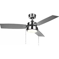
Preston CF52PR35BK - Fan Canarm - Free user manual and instructions
Find the device manual for free Preston CF52PR35BK Canarm in PDF.
User questions about Preston CF52PR35BK Canarm
0 question about this device. Answer the ones you know or ask your own.
Ask a new question about this device
Download the instructions for your Fan in PDF format for free! Find your manual Preston CF52PR35BK - Canarm and take your electronic device back in hand. On this page are published all the documents necessary for the use of your device. Preston CF52PR35BK by Canarm.
USER MANUAL Preston CF52PR35BK Canarm
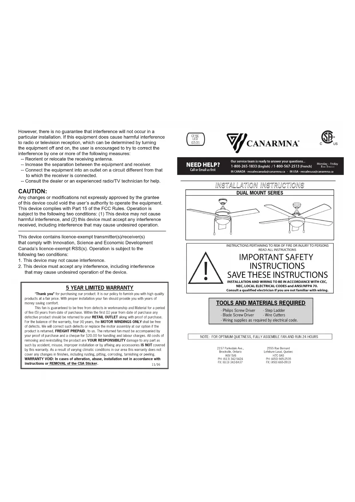
- Philips Screw Driver- Blade Screw Driver- Step Ladder- Wire Cutters- Wiring supplies as required by electrical code. INSTRUCTIONS PERTAINING TO RISK OF FIRE OR INJURY TO PERSONSREAD ALL INSTRUCTIONS IMPORTANT SAFETY INSTRUCTIONS
SAVE THESE INSTRUCTIONS
INSTALLATION AND WIRING TO BE IN ACCORDANCE WITH CEC,NEC, LOCAL ELECTRICAL CODES and ANSI/NFPA 70. Consult a qualified electrician if you are not familiar with wiring.DUAL MOUNT SERIES “Thank you” for purchasing our product. It is our policy to furnish you with high quality products at a fair price. With proper installation your fan should provide you with years of money saving comfort. This fan is guaranteed to be free from defects in workmanship and Material for a period of five (5) years from date of purchase. Within the first (1) year from date of purchase any defective product should be returned to your RETAIL OUTLET along with proof of purchase. For the balance of the warranty, four (4) years, the MOTOR WINDINGS ONLY shall be free of defects. We will correct such defects or replace the motor assembly at our option if the product is returned, FREIGHT PREPAID, to us. The returned fan must be accompanied by your proof of purchase and a cheque for $20.00 for handling and labour charges. All costs of removing and re-installing the product are YOUR RESPONSIBILITY damage to any part as such by accident, misuse, improper installation or by affixing any accessories IS NOT covered by this warranty. As a result of varying climatic conditions in our area this warranty does not cover any changes in finishes, including rusting, pitting, corroding, tarnishing or peeling. WARRANTY VOID: In cases of alteration, abuse, installation not in accordance with
5 YEAR LIMITED WARRANTY
11/16 .rekcitS AS C eht fo LAVOMER ro snoitcurtsni CF-5E LED 07/21 2555 Rue Bernard Lefebvre Laval, Quebec H7C 0A5 PH: (450) 665-2535 FX: (450) 665-0910 2157 Parkedale Ave., Brockville, Ontario K6V 5V6 PH: (613) 342-5424 FX: (613) 342-8437 However, there is no guarantee that interference will not occur in a particular installation. If this equipment does cause harmful interference to radio or television reception, which can be determined by turning the equipment off and on, the user is encouraged to try to correct the interference by one or more of the following measures: -- Reorient or relocate the receiving antenna. -- Increase the separation between the equipment and receiver. -- Connect the equipment into an outlet on a circuit different from that to which the receiver is connected. -- Consult the dealer or an experienced radio/TV technician for help. CAUTION: Any changes or modifications not expressly approved by the grantee of this device could void the user’s authority to operate the equipment. This device complies with Part 15 of the FCC Rules. Operation is subject to the following two conditions: (1) This device may not cause harmful interference, and (2) this device must accept any interference received, including interference that may cause undesired operation. This device contains licence-exempt transmitter(s)/receiver(s) that comply with Innovation, Science and Economic Development Canada’s licence-exempt RSS(s). Operation is subject to the following two conditions:
1. This device may not cause interference.
2. This device must accept any interference, including interference
that may cause undesired operation of the device.Pg. #2Pg. #11 TROUBLESHOOTING TROUBLESUGGESTIONS- Check fuses and circuit breakers.1. Fan will not start - Check wiring connections to fan.- Check wiring connections in switch housing.CAUTION: Turn power off for last two items.2. Fan sounds noisy - Check to make sure that all screws in motor housing are snug.- Check to make sure that blade bracket screws are tight.- Check to make sure that marrettes in switch housing are not rattling against wall of switch housing.- If fan has a light kit make sure switch housing screws and set screws are tight.- Some fan motors are sensitive to signals from solid state variable controls. If solid state controller isused, change to an alternative control. (See a representative for a list of available controls.)- Allow a 24 hour break in period to eliminate most noises.
Fan wobbles - Check that all blades are screwed firmly into blade brackets.or shakes excessively.- Check that blade brackets are secured firmly to motor.- Check distance from tip of blades to ceiling. Check distance between blade tip to blade tip. All measurements should be equal. Loosen blade screws and position blade until even then re-tighten.- Check that the downrod hemisphere notch is engaged in canopy. - Check to make sure that jam screws in downrod are tightened.- Make sure canopy and mounting bracket are tightened securely to wooden joist.- Make sure warpage has not occurred in wooden blades. If so, contact the customer service department for replacement parts. - To r
chain WARNING educe the risk of fire or electrical shock, ONLY use model CQ006 remote control for optional remote control adaptability.
with the lowest moving parts at least 2.10 Meters (7 Feet) above grade level. NOT operate reversing switch while fan blades are in motion. Fan must turned off and rotating blades stopped, reverse chain pulled, the speed pulled again
the opposite direction. INSTRUCTIONS A ceilling fan has a completeky internal switchung system for total operation by way
pull chains.On a fan/light combination, pull chains will exist: One for light,
and off. The second is for fan speeds. This will be marked (SPEED) on the fanswitch housing. 1st Pull will give fan High Speed 2nd Pull will give fan Medium Speed 3rd Pull will give fan Low Speed 4th Pull will Shut Fan Off The third pull chain
for Forward/Reverse#(Note: Some models come with
pull chain). This setting would usually
changed twice per year. Downdraft
cooling effect. Updraft
circulate the hot stratified air off the ceilling and back down
the floorwithout creating
wind chill. three This equipment has been tested and found to comply with the limits for a Class B digital device, pursuant to Part 15 of the FCC Rules. These limits are designed to provide reasonable protection against harmful interference in a residential installation. This equipment generates, uses and can radiate radio frequency energy and, if not installed and used in accordance with the instructions, may cause harmful interference to radio communications. Supplier's Declaration of Conformity 47 CFR § 2.1077 Compliance Information Unique Identifier: CANARMNA Responsible Party CanarmInc. 709 East Main Street, Teutopolis, Illinois, USA 62467
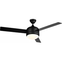
SAFETY PRECAUTIONS 1. Turn off power at main electrical service box before starting installation2. Electrical connections must comply with local code ordinances, national electrical codes, CEC, NEC and ANSI/NFPA 70.3. Make sure the installation site you choose allows the fan blades to rotate freely without any obstructions.4. When mounting the fan on a ceiling outlet box, Use an approved (CSA for Canada and UL for U.S.) ceiling fan box marked "FOR FAN SUPPORT". Ensure the outlet box is securely installed in place such that it is able to support at least the fan weight.5. WARNING: To reduce the risk of fire, electric shock, or other personal injury, mount fan only on an outlet box or supporting system marked acceptable for fan support of 35 lbs (15,9 kg) or less and use the mounting screws provided with the outlet box. Most outlet boxes commonly used for the support of lighting fixtures are not acceptable for fan support and may need to be replaced. Consult a qualified electrician if in doubt.6. Total Fan Weight For Reference: 48"approximate 8.0 kgs(17.63lbs). 52"approximate 9.0 kgs(19.84lbs).Pg. #10 Pg. #3 ASSEMBLY DRAWING A. Mounting Bracket B. Canopy C. Downrod Assembly D. Yoke Cover E. Fan Motor Assembly F. Motor Cover G. Glass
LIGHT ASSEMBLY - Place glass onto the fan and turn to secure. MotorGlassLight Kit Fig.8 WARNING: Check all connections, set screws and screws a resecu rely tightened before the next step.To clean the fixture, turn off the power, wait for it to cool, and wipe the fixture with a clean, soft cloth.1
MOUNTING FAN ASSEMBLY
- Place two screws and washers on mounting plate (marked B on diagram) which correspond with slots in canopy. Screw in two turns.- Position canopy to mounting plate aligning slots to screws (marked B on diagram) then turn to lock.- Position and tighten the two screws and washers (marked A on diagram) then tighten the two screws (marked B on diagram).
ENGAGE HEMISPHERE (Downrod Mount Only) - Carefully rotate fan assembly until groove in hemisphere locks over tab of canopy assembly.CONNECTING BLACK, WHITE, AND (RED OR BLUE) WIRESNOTE: Once wires are connected, carefully tuck wires and marrettes into the outlet box making sure that the wires are clear of the hemisphere and downrod when positioned in mounting bracket (Downrod Mount Only). - Connect white wire from outlet box to whitewire from fan using marret (not supplied).- Connect black wire from outlet box to blackwire from fan plus (red or blue wire) using a marret.NOTE: A red or blue wire would be power for a light kit if applicable.NOTE: When installing fan on sloped ceiling, make sure tab on hanger bracket faces towards the top of the slope. Depending on the slope, a longer downrod may be required to prevent fan blades from hitting the ceiling. GrooveFig.7b
For model CalibreDownrodHemisphereWARNING: Failure to seat tab in groove could cause damage to electrical wires and possible shock or fire hazard.VI : Fig.2a and 2bFig.7a (A) (B) (B) Washers (A) Glass Plastic Screw Fig.2cChainFig.2b Red or Blue Wires WhiteWires Blackor Blue Wires Light Kit Screw Light Kit - Install the light kit to the fan motor assembly by tightening 4 screws.- Connect polarized connectors of light kit to corresponding connectors found in switch housing.- Remove the 4 plastic screw from light kit.- Install the glass an the light kit by tightening the 4 plastic screw. Black Wire White Wire Red or Blue Wire Fig.6 White WirePg. #8Pg. #5 INST INST ALLA ALLA TION TION NOTE: All set screws must be checked andretightened where necessary, before and after installation.
- Attach the blades to the fan motor assembly using the screws, metal washer and fibre washer. Slightly turn the blade after installation and repeat the same step for the other blades. - Re-attach the cover to the top housing. ELECTRICAL HOOK-UP
BladeBlade Bracket Screw Screw Fibre Washer For model Preston III or Cove II or Moderne IV or CAUTION SEE SAFETY PRECAUTIONS ONPG. #2 BEFORE WIRINGGreen Wire - GROUNDBlack Wire (Fan) - POWERWhite Wire (Fan) - COMMONRed or Blue Wire (Light Kit) - POWER - There are several different wiring combinations that can be used in controlling your ceiling fan to meet your specific requirements. Should the following method not meet your requirements call or visit your nearest distributor for a full list of fan accessories.After making the wire connections, ensure the wires should be spreadapart with the grounded conductor and the equipment-groundingconductor on one side of the outlet box and the ungrounded conductoron the other side of the outlet box.Ensure the splices after being made should be turned upward andpushed carefully up into the outlet box.
CONNECTING THE (GREEN) GROUND WIRE
NOTE: Once ground wires are connected, carefully tuck wires and into the outlet box making sure that the wires are clear of the hemisphere and downrod when positioned in mounting bracket (Downrod Mount Only).
- Remove the cover on the top housing. Mill: Fig. 2 c , 2 d and 2 e DOWNROD MOUNT FLUSH MOUNT - Connect ground wire from outlet box to green wire from mounting bracket and downrod using a(not supplied).- Connect ground wire from outlet box to green wire from mounting bracket using a (not supplied). Fig. 5b Fig. 5a marette marette MaretteMarettePg. #6Pg. #7
MOUNTING DOWNROD MOUNT
- Install J-Hook through centre of outlet box and into the wooden joist.- Secure mounting bracket and rubber gaskets to outlet box.- Hang the safety cable onto the J-hook.WARNING: To Reduce The Risk Of Fire, Electric Shock, Or PersonalInjury, Mount To UL/CSA Listed Outlet Box Marked Acceptable forFan Support And Use Mounting Screws Provided With The Outlet Box. FLUSH MOUNT
CanopyRubber RingMotorCanopyYoke Screws& WashersRubber Bushing FLUSH MOUNT - Remove rubber ring from canopy.- Place canopy on fan housing by alinging 3 larger holes of canopy over 3 existing screws on the motor housing.- Secure canopy to motor housing by placing 3 screws and washers (supplied in hardware package) in the 3 smaller holes in the canopy.
- Insert bolt through hole in shaft and downrod. Be careful not to damage or cut the fan wires.- Tighten flat washer and bolt. Secure with cotter pin through hole in the end of the bolt.- Secure downrod in position by tightening jam screws. Slide yoke cover down so it is flush with the motor housing.- Take out fan
Remove cotter pin and bolt from yoke.- Loosen jam screw in yoke until it is flush with the inside surface.- Obtain downrod, canopy and yoke cover.- Place downrod inside canopy and yoke cover.
Route wires exiting motor through yoke cover, canopy and downrod.Fig. 3fFig. 3g- Hang fan on temporary hook or mounting bracket.Motor Bolt Yoke Jam Screw Jam ScrewDownrodCanopyYoke Cover Bolt Flat WasherCotter Pin Yoke Jam Screw Fig. 3d Fig. 3e Fig. 3b CotterFlat Washer Pin Fig. 3c Fig. 3a Ceiling Outlet box Screws (not provided) Fig.4a Tomporary Hook Canopy Safety Cable Fig.4c J-Hook Safety Cable Canopy Fig.4b J-Hook Wood Joist Outlet Box Rubber Gasket Mounting Bracket Diagram Fig.4b is for Downrod Mount.Diagram Fig.4c is for Flush Mount.M