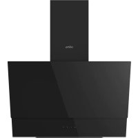
ORC60BG - Range hood Orima - Free user manual and instructions
Find the device manual for free ORC60BG Orima in PDF.


| Product Type | Kitchen hood |
| Brand | Orima |
| Model | ORC60BG |
| Category | Wall-mounted chimney hood |
| Width (mm) | 600 |
| Depth (mm) | 470 |
| Minimum height (mm) | 782 |
| Maximum height (mm) | 1112 |
| Air outlet diameter (mm) | 150 |
| Power supply | 220-240 V ~ 50 Hz |
| Recommended fuse | Max 6 A |
| Control type | Touch (4 buttons or digital) |
| Number of speeds | 3 |
| Lighting | LED |
| Timer | Yes (15 min) |
| Air cleaning function | Yes (10 min on / 50 min off cycle for 24h) |
| Grease filter | Aluminum cassette, dishwasher-safe |
| Charcoal filter (optional) | Round, replace every 3-5 months |
| Maintenance | Clean metal filter once a month |
| Minimum hob-hood distance (gas) | 65 cm |
| Use | Domestic |
| Warranty | Subject to installation by a qualified professional |
Frequently Asked Questions - ORC60BG Orima
User questions about ORC60BG Orima
0 question about this device. Answer the ones you know or ask your own.
Ask a new question about this device
Download the instructions for your Range hood in PDF format for free! Find your manual ORC60BG - Orima and take your electronic device back in hand. On this page are published all the documents necessary for the use of your device. ORC60BG by Orima.
USER MANUAL ORC60BG Orima
MANUAL DE INSTRUÇÕES
INSTRUCTION MANUAL LIVRE D'INSTRUCTIONS LIBRO DE INSTRUCCIONES
www.orima.pt
facebook.com/orima.pt
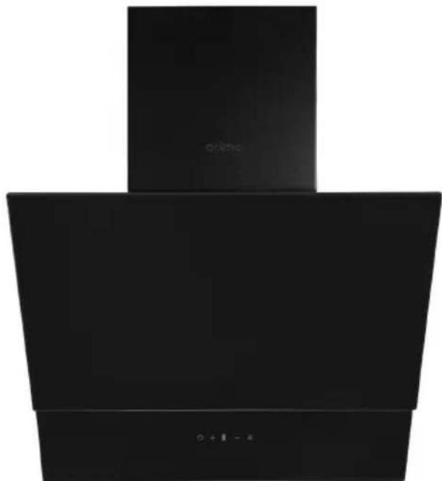
natural_image
Black industrial kitchen range hood with ventilation grille and control buttons (no text or symbols visible)
MMA
MAGRO MELANDA DE ALMEIDA
EXAUSTOR
Built-in Exhauster | Campana Inscrustación | Exhauster Encastre
ORC-60-BG
SERVIÇO DE APOIO AO CLIENTE
Apoio ao Cliente:
Tel.: (+351) 231 467 436
natural_image
Line drawing of a mechanical device with a lever and base, labeled 'Figura 1' (no text or symbols on the diagram itself)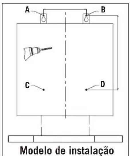
natural_image
Technical line drawing of a mechanical device with a drill bit and labeled 'Figura 2' (no other text or symbols)natural_image
Line drawing of a hand using a tool to adjust or install a mechanical component (no text or symbols present)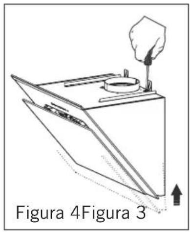
4.1. Nivelar o exaustor de chaminé
natural_image
Line drawing of a hand using a tool to interact with a circular device on a base, labeled Figura 5 (no text or symbols on the diagram itself)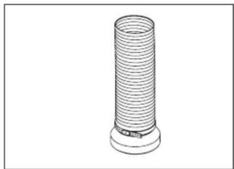
natural_image
Line drawing of a cylindrical mechanical component with a base and protruding end (no text or symbols)PO
natural_image
Symbol of a trash bin crossed with no text or numbers, representing waste sorting or disposal (no text present)Thank you very much for your preference for products. Our objective is to ensure that you enjoy this product, manufactured environmentally-friendly with a total sense of quality in a precise working environment at our modern facilities, most efficiently.
We recommend you to read the instruction manual carefully and keep it handy before you use this chimney hood so that it maintains its quality just like the first day you bought it and serves you most efficiently.
Note: This instruction manual has been prepared for a variety of models. Some of the features specified in the Manual may not exist in your device.
These features are marked with *.
Our devices are designed for domestic use. They are not for professional use.
"PLEASE READ THE INSTRUCTIONS BEFORE YOU INSTALL OR USE THIS DEVICE."
This product has been manufactured in an environmentally-friendly and modern plants without harming the nature.
"Conforms with the AEEE Regulations."
Contents
- Safety Instructions 20
- Introduction And Technical Drawing Of The Chimney Hood 23
- Installation Of Chimney Hood 24
3.1. Location Of The Chimney Hood 24
3.2. Installation Of Mounting Bracket To The Chimney Hood 24
3.3. Installation Of Wall Mounting Bracket 24
3.4. Installation Of Inner Duct Mounting Bracket 25 - Mounting The Chimney Hood On The Wall 25
4.1. Leveling The Chimney Hood 25
4.2. Mounting The Aluminum Pipe 25 - Functions Of The Chimney Hood 26
5.1. Control Panel 26
5.2. Symbols Functions 26
5.3. Four Button Touch Control 27
5.4. Screenless Touch Control 28 - Operating The Chimney Hood 28
6.1. In Ducted Use 29
6.2. Round Charcoal Filter 29
6.3. Use Of Charcoal Filter 29
6.4. Installation Of Charcoal Filter 29
6.5. Use Of Aluminum Cartridge Filter 29 - Replacing The Bulb 30
- Maintenance Of The Chimney Hood 30
- If Chimney Hood Does Not Work 31
- Environmentally-Friendly Disposal 33
- Package Information 33
SAFETY INSTRUCTIONS
- The installation of the product should be carried out by authorized persons. Installation performed by unauthorized persons may result in poor performance, damage to the product or accidents. The product will not be covered by the warranty.
- When an electric cooker hood is used simultaneously with the devices which burn gas or other fuels, the room should be ventilated adequately (not applicable for devices that discharge air back into the room).
- An electric cooker hood should not be connected to a flue or air duct used to drain smoke from devices which burn gas or other fuels (oven, water heating thermosyphon, etc.) (not applicable for devices that discharge air back into the room).
- Comply with the instructions regarding discharge of outlet air, stipulated by the relevant authorities (not applicable for devices that discharge air back into the room).
-
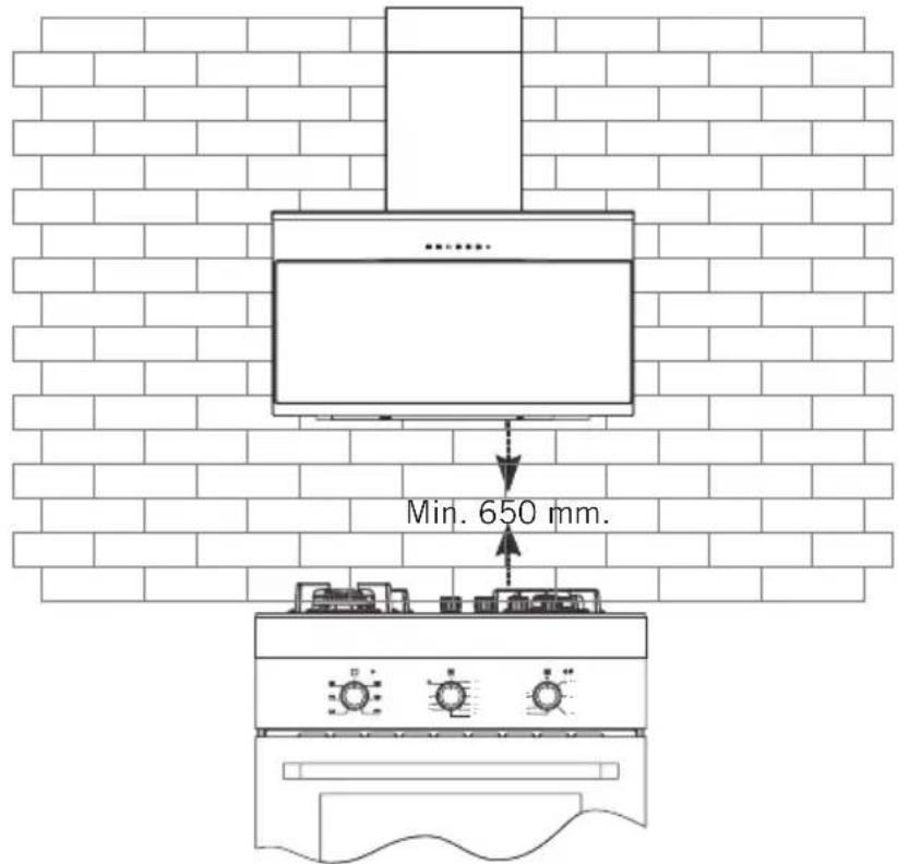
When the cooker hood is placed on a gas burning device, the distance between the hob and the hood should be at least 65 cm. If a larger distance is specific in the installation instructions of the gas burning hobs, this value should be taken into account.
-
Packaging materials may be dangerous for children. Do not allow children to play with packaging materials. Keep packaging materials out of reach of children.
- This device is not designed to be used by children, people with physical, sensory or mental incapabilities, or with lack of experience or technical knowledge. Do not allow the persons and children under custody to use the product, play with the product, to perform maintenance and cleaning on the product.
- Kitchen hoods are designed for domestic use. They should not be used for other purposes. Otherwise, it may cause various accidents and the device will be out of warranty.
- The electrical connection of the product must be done to a grounded outlet.
- Before the installation, maintenance and cleaning of the product, de-energize the device. (By unplugging the device or by switching off the fuse)
- For your safety, use "Max 6 A" fuses in the hood installation.
- Do not operate the hood without using cookwares. High heat may cause some parts of your product to deform and cause fire.
- Do not leave boiling oil on the stove. Pots that contain boiling oil may catch fire by itself.
GB
- Clean the oil trap aluminium filters regularly. Filters pose risk of fire due to accumulated grease deposits on them.
- Do not operate your product without filter, and do not remove the filters when the product is in operation. Do not use non-fire-resistant filtering materials instead of the filter.
- Flammable foods must not be cooked under the appliance.
- Risk of fire may occur if cleaning is not carried out periodically and according to instructions.
- In case of any fire, de-energize devices. Cover the flames with a damp cloth or towel. Never use water to put out the flames.
- The mains cable should not be passed near stoves, or devices or equipment which may come into contact with heat or which may deform the cable. This may cause fire.
- Do not touch your product's lamps when they work for a long time. Since they would be hot, they could burn your hand.
- CAUTION: Accessible sections may be hot when used with cooking appliances.
- WARNING: Failure to install screws or fixing installations in accordance with these instructions may result in electrical hazards.
2. INTRODUCTION AND TECHNICAL DRAWING OF THE CHIMNEY HOOD
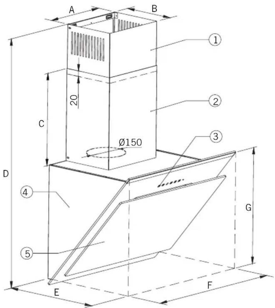
- Inner flue plate
- Outer flue plate
- Control keys
- Plate body
- Cover glass
| PRODUCT MODELS | MDD*-056... | MDD*-059... | MDD*-216... | MDD*-56... | MDD*-146...MDD*-256...MDD*-266...MDD*-346... | MDD*-236...MDD*-246... | MDDX-286... | MDDX-276... | MDDX-306... | MDDX-296...MDDX-316...MDDX-326...MDDX-366... | |
| A | 265 265 | 265 310 200 | 200 265 265 2 | 55 265 | |||||||
| B | 210 210 | 216 290 170 | 170 210 210 2 | 16 210 | |||||||
| C | 350 350 | 350 350 300 | 300 350 350 3 | 50 350 | |||||||
| D | Min | 782 782 | 772 635 662 | 662 840 783 8 | 50 781 | ||||||
| Max | 1112 1112 | 1002 965 942 | 942 1170 1 | 113 1180 1115 | |||||||
| E | 460 460 | 450 450 410 | 395 385 430 4 | 40 445 | |||||||
| F | 595 895 | 595 595 595 | 595 595 595 5 | 595 595 | |||||||
| G | 470 470 | 440 465 362 | 362 505 450 5 | 505 448 | |||||||
All dimensions are in millimeter.
3. INSTALLATION OF CHIMNEY HOOD
3.1. Location Of The Chimney Hood
3.2. Installation Of Mounting Bracket To The Chimney Hood
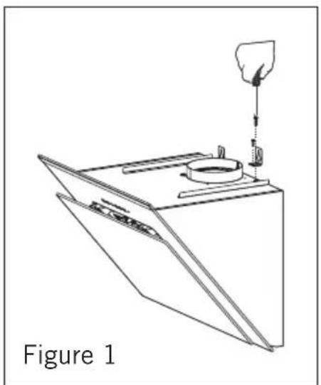
Fix the 2 (two) Mounting brackets among the installation accessories to the chimney hood with one 1 screw nut as shown in Figure 1. Make sure mounting brackets are inserted in motor box.
3.3. Installation Of Wall Mounting Bracket
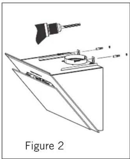
Drywall (8mm) anchors are nailed into the holes drilled according to installation template (A,B,C,D). They are fixed into the wall with 2 brackets as shown in Figure 2.
natural_image
Line drawing of a mechanical device with a handle and internal components, labeled 'Figure 1' (no text or symbols on the diagram itself)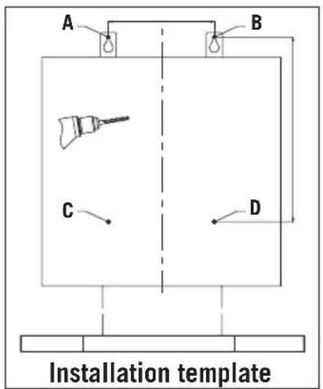
natural_image
Technical line drawing of a mechanical assembly with a drill bit and labeled Figure 2 (no text or symbols on the diagram itself)3.4. Installation Of Inner Duct Mounting Bracket
2 fixing holes are drilled on the wall with ∅ 6 mm electric drill at a suitable height and place to fix the inner duct hanger plate onto the wall. 6mm drywall anchors are nailed into those holes and inner duct mounting brackets are pinned down. At the last step of chimney hood installation, the inner duct is screwed on the inner duct mounting brackets.
4. MOUNTING THE CHIMNEY HOOD ON THE WALL
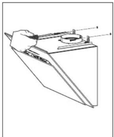
Lift the chimney hood body and fix the hanger plates onto the wall anchors as shown in Figure 3.
natural_image
Line drawing of a hand holding a tool over a mechanical component (no text or symbols)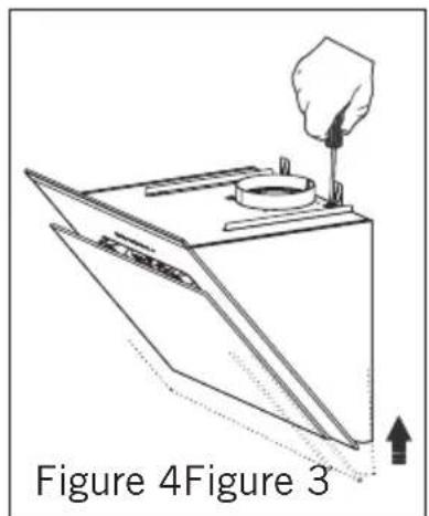
4.1. Leveling The Chimney Hood
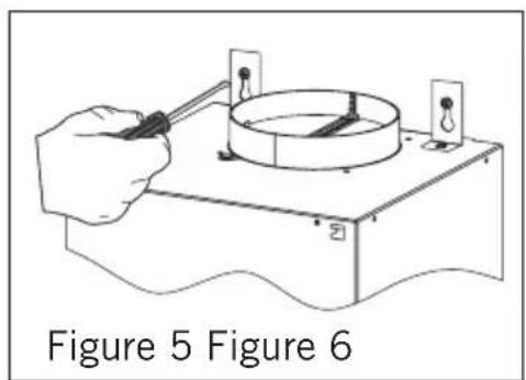
If the chimney hood is inclined on one side, the chimney hood can be leveled with the adjustment screws as shown in Figure 4. Once the balancing is complete, the screws shown in Figure 5 must be fixed tightly. After this, fix the body with one screw through the hole on the body.
4.2. Mounting The Aluminum Pipe
Place the aluminum pipe on the plastic duct. Place the other end of the pipe into the air outlet in the kitchen. (Figure 6)
natural_image
Illustration of a hand using a tool to test a circular object on a base, labeled Figure 5 (no text or symbols on the diagram itself)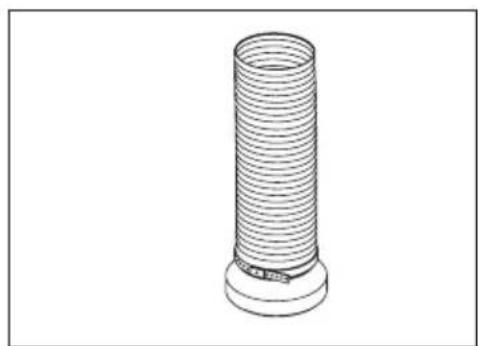
natural_image
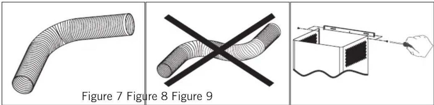
Line drawing of a cylindrical mechanical component with a base and protruding end (no text or symbols)Twists and bends on the aluminum pipe may cause minimizing the air suction so avoid unnecessary bends and twists as much as possible. (Figure 7-8) Place the inner duct and outer duct carefully on the product. Fix the inner duct to inner duct connection plate with 2 screws. (Figure 9)
5. FUNCTIONS OF THE CHIMNEY HOOD
5.1. Control Panel
Digital Control: Touch the symbols on the keys. (On/Off function and timer are on the same key; if pressed for 1 sec on-off function will operate. If pressed for 3 sec. 15 minutes timer will operate.
Touch Control: Touch the symbols on the glass surface. If Press a symbol longer (more 3 sec) may operate various functions.

5.2. Symbols Functions
 | Switches on and off the motor. (Except for the lighting) | Increases the speed when the motor is running. | |
 | Decreases the speed when the motor is running. | If pressed this symbol, the motor turns itself off 15 minutes later. | |
 | Display | Only switches on and off the lighting system. |
Note: When the product operates for a certain time, the aluminum filters get dirty and the digital display shows “C” Clean sign. This means the filters should be cleaned. Press the speed reduction key for 5 secs in order to delete “C” sign from the display.
CAUTION: When the timer key is pressed for 3 secs digital display starts to change. Air-circulation system of the chimney hood becomes active. The chimney hood runs for 10 minutes in the lowest speed. Then the system automatically shuts down.
5.3 Four Button Touch Control\*
ON/OFF Button Plus Button Minus Buttoner
Lamp
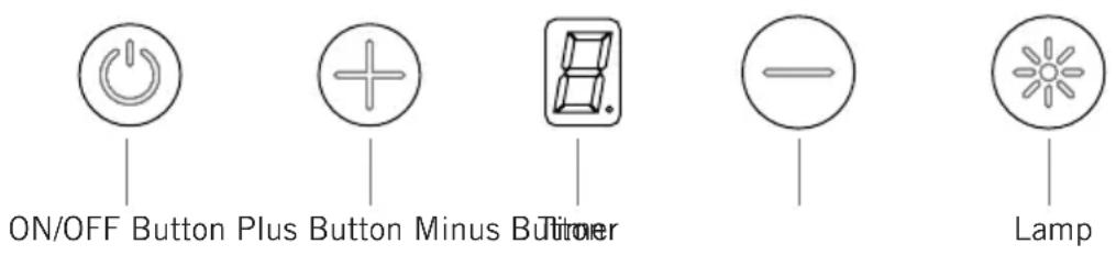
- ON&OFF: Starts the motor.
- Speed +: Increase the speed of the motor. Max: 3 speed.
- Speed -: Decrease the speed of the motor. Max: 1 speed.
- Lamp: Turns the lamp on. When the lamp is on, the dot segment is viewed on the screen.
- Timer: If the lamp button is pressed for 3 seconds, the device starts flashing in respective speed. After 15 minutes the device is turned off.
- Air Cleaning: When the air cleaning button is pressed on the RemoteControl, the function is initiated. Themotorisoperated for 10 minutes in 1 speed, then switch chest stand by for 50 minutes. While this function is active, these screen segments start rotating. Then the system shuts down automatically. The rotation is only for 24 hours.
- Filter Warning: At the end of 100 hours of operation, the 'C' warning is viewed on the screen. This warning can be deleted by pressing the speed - button for 5 seconds, the 'E' is viewed on the screen, the warning is deleted and the timer is reset. This warning is viewed for 2 seconds when on/off button is pressed. During rotation changes this warning is not displayed.
- Automatic Shutdown: For safety purposes, the circuit board of the motor is programmed to provide maximum of 5 hours lighting and maximum 10 hours of operation. When the air cleaning function is in effect, the motor shutdown feature is turned off.
5.4. Screenless Touch Control \*
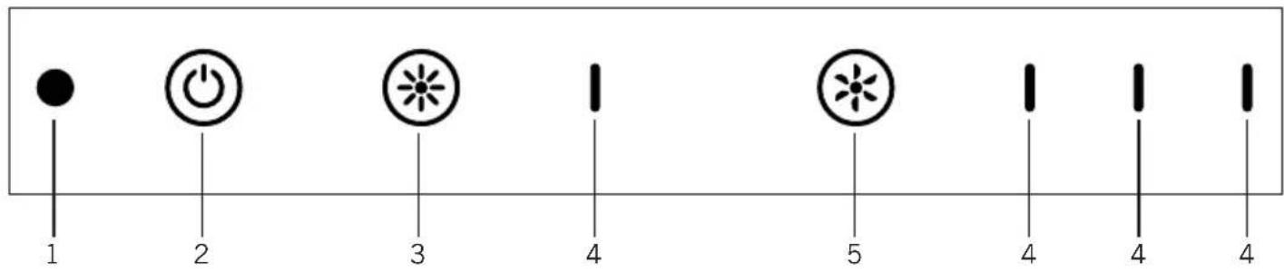
- Receiver
- ON / OFF Button
-
Light
-
LED
- Speed Adjustment Button
• ON&OFF Button: Starts the engine.
- Timer: To activate, press and hold the ON / OFF for 3 seconds. Operating duration is 15 minutes at the adjusted cycle. The appliance shuts down at the end of this duration. During the operation, the activated engine LED flashes.
- Air Cleaning: To activate the function, press the air cleaning button on the remote control. On cycle 1, the engine operates for 10 minutes and then stays on stand by mode for 50 minutes. This cycle continues for 24 hours.
When this function is active, the engine ON / OFF button LED flashes. Then the system automatically shuts down. The cycle runs only for 24 hours.
- Light ON / OFF Button: Turns the light on and off. When the light is on, the first LED is activated.
- Cycle Adjustment Button: It increases the cycle speed while the engine is in operating state. If pressed when the cycle is on the top speed, the engine goes back to cycle 1.
Cycle LEDS:
2nd LED: Activated when the engine operates at cycle 1.
3rd LED: Activated when the engine operates at cycle 2.
4th LED: Activated when the engine operates at cycle 3.
Chimney hood is used in ducted and non-ducted kitchens.
6.1. In Ducted Use
In ducted use, extractor fan should be connected to an air outlet to send the air out. In order to use your chimney hood efficiently, make sure length of the pipe system between the chimney hood and the air outlet should be short. Your product has been manufactured suitable for ducted and non-ducted use.
6.2. Round Charcoal Filter
In kitchens with no duct, a round charcoal filter should be reintroduced the clean air into the kitchen. You can obtain the round filter from your service or dealer.
6.3. Use Of Charcoal Filter
- Our products allow the installation of charcoal filter.
- Regardless of use of charcoal filters or not, grease filters should be installed on the product. Do not use your product without grease filter.
- Use of charcoal filteris as follows.
- Cut off the device power before replacing charcoal filter.
- Charcoal filter is used in the kitchens with no duct therefore should be replaced in every 3-5 months depending on the frequency of use.
- Charcoal filter should never be washed.
6.4. Installation Of Charcoal Filter
- Charcoal filters are used in the kitchens with no duct.
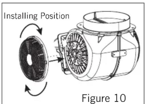
- Charcoal filters are installed onto both sides of the fan as shown in Figure 10 by turning 10 degrees clock-wise.
- When uninstalling, reverse the same procedure.
6.5. Use Of Aluminum Cartridge Filter
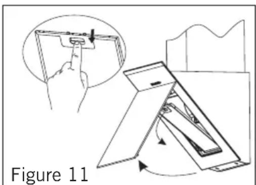
Aluminum cartridge filter holds dust and grease in the air. Chimney hood should never be used without aluminum cartridge filter. (Figure 11)
7. REPLACING THE BULB
Always switch off the electrical supply before carrying out any operation
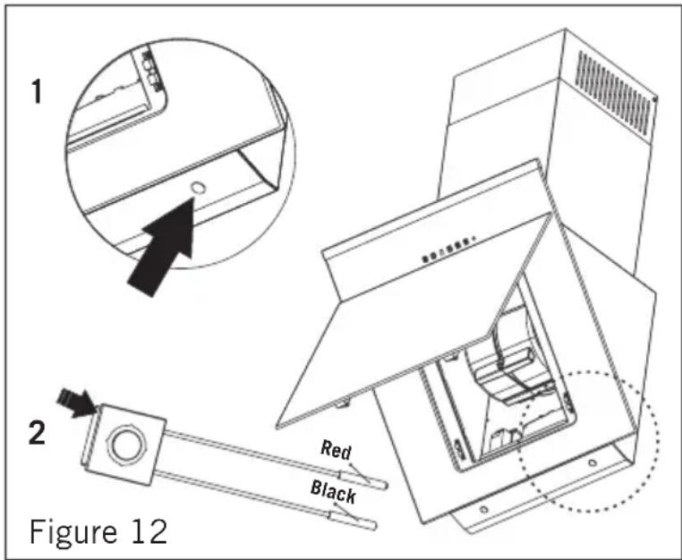
LED bulb does not operate is possible to remove as shown in
Figure 12
A new bulb to be supplied from service points is replaced with the same reoperation.
Cables are designed with sockets. The plug in should be made according to previous connection.
Note: Remove the holder on the LED bulb as shown in Figure 12.2. Put the new LED bulb on the holder housing of the LED bulb you removed as shown in Figure 12.1.
8. MAINTENANCE OF THE CHIMNEY HOOD
- Device should be unplugged or switch should be turned off before cleaning and maintenance procedures.
- Metal filter should be cleaned once a month with hot soapy water or in the dishwasher, if possible. (60 °C)
- Remove the aluminum cartridge filter by pressing on the spring catches on the side. Do not refit before drying after wash.
- Outer surface of the extractor hood should be wiped with a damp cloth soaked with soapy water.
- Make sure electronic parts do not contact with water or similar materials.
- For inox products, using inox cleaning and maintenance products available in the market will provide longer usage life for your device.
- Aluminum filters can be washed in dishwasher. After several washes, aluminum filters may change colour. This is normal and filters do not need to be replaced.
WARNING: When used with devices which use fuel (heaters working with gas, diesel fuel, coal or firewood, water heaters, etc) and the air in the environment; should be used cautiously. The chimney hood sending the air out in the environment may affect the burning adversely.
This warning is not applicable to non-ducted use.
Efficient Use Of Chimney Hood;
- When installing the chimney hood to the air duct, use 150/120 mm diameter pipes and use bends as minimum as possible.
- Be ware of cleaning periods of metal filters and replacing times of charcoal filters.
- When dense suction power is not required, use the product in medium setting.
- For right ventilation, the windows in the kitchen leading to the outside should be kept closed.
9. IF CHIMNEY HOOD DOES NOT WORK;
Before contacting the service, make sure the product is plugged and the fuse in the electrical installation is working. Do not do anything that may harm the product.
Service And Spare Parts
Have one of our authorized services install your device free of charge.
You can supply spare parts of your device from your dealer or authorized services. The package includes a list of authorized services with the product.
When you contact your service or dealer to ask for any spare parts, notify them of product model name shown in the product label. When you remove the aluminum cartridge filter, you will see the product label.
Before contacting your service, check your chimney hood against the table below. If problem persists, contact your dealer or authorized service point.
| Check electricity connection (mains voltage should be 220-240 V, Chimney hood should be connected to grounding socket.) | Check motor switch (Motor switch should be on.) | Check bulb switch (Bulb switch should be on.) | Check aluminum filter (Aluminum cartridge filter should be washed once a month in normal use.) | Check bulbs (Bulbs should be in working condition.) | Check air outlet shaft (Air outlet shaft should be unblocked.) | Check charcoal filter (Charcoal filters should be replaced quarterly in normal use. | |
| Chimney Hood does not work |  | ||||||
| Light bulb is not working |  |  |  | ||||
| Chimney hood air suction is poor |  | √ |  | ||||
| Do not send air out (in non-ducted cases) |  | √ | |||||
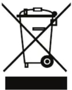
10. ENVIRONMENTALLY-FRIENDLY DISPOSAL
natural_image
Symbol of a trash bin crossed with diagonal lines, no text or numbers presentDispose of packaging in an environmentally-friendly manner.
This appliance is labelled in accordance with European Directive 2012/19/EU concerning used electrical and electronic appliances (waste electrical and electronic equipment - WEEE). The guideline determines the framework for the return and recycling of used appliances as applicable throughout to the EU.
11. PACKAGE INFORMATION
Packaging materials of the product are manufactured from recyclable materials in accordance with our National Environment Regulations. Do not dispose of the packaging materials together with the domestic orotherwastes. Takethemtothepackagingmaterialcollectionpoints designated by the local authorities.
Estimado Cliente,
natural_image
Line drawing of a mechanical device with a funnel and base, labeled Figura 1 (no text or symbols on the diagram itself)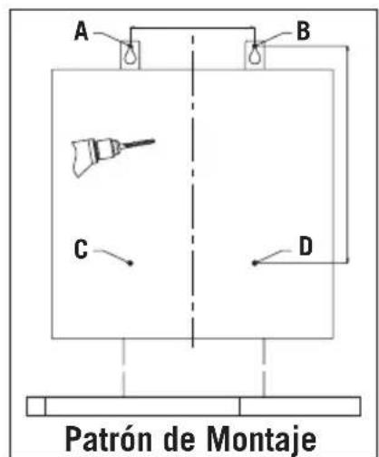
natural_image
Technical line drawing of a mechanical device with a drill bit and base plate (no text or symbols)3.4. Montaje De La Placa De Gancho De La Chimenea Interior
natural_image
Line drawing of a hand using a tool to press or install a mechanical component (no text or symbols present)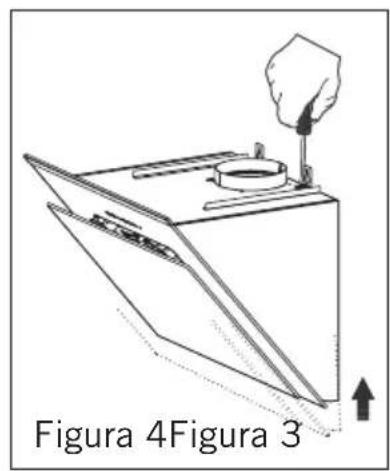
natural_image
Illustration of a hand using a tool to test a circular object on a base, labeled Figura 5 (no text or symbols on the diagram itself)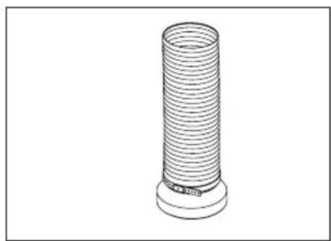
natural_image
Line drawing of a cylindrical mechanical component with a base and protruding end (no text or symbols)natural_image
Symbol of a trash bin crossed with diagonal lines, no text or numbers presentnatural_image
Technical line drawing of a mechanical assembly with a drill bit and tool, no text or symbols presentnatural_image
Technical line drawing of a mechanical assembly with a hand holding a tool, no visible text or symbols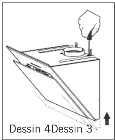
natural_image
Line drawing of a cylindrical mechanical component with a base and protruding end (no text or symbols)natural_image
Symbol of a trash bin crossed with diagonal lines, no text or numbers present


- MANUAL DE INSTRUÇÕES
- EXAUSTOR
- ORC-60-BG
- SERVIÇO DE APOIO AO CLIENTE
- Nivelar o exaustor de chaminé
- PO
- "PLEASE READ THE INSTRUCTIONS BEFORE YOU INSTALL OR USE THIS DEVICE."
- "Conforms with the AEEE Regulations."
- Contents
- SAFETY INSTRUCTIONS
- GB
- INTRODUCTION AND TECHNICAL DRAWING OF THE CHIMNEY HOOD
- INSTALLATION OF CHIMNEY HOOD
- Location Of The Chimney Hood
- Installation Of Mounting Bracket To The Chimney Hood
- Installation Of Wall Mounting Bracket
- Installation Of Inner Duct Mounting Bracket
- MOUNTING THE CHIMNEY HOOD ON THE WALL
- Leveling The Chimney Hood
- Mounting The Aluminum Pipe
- FUNCTIONS OF THE CHIMNEY HOOD
- Control Panel
- Symbols Functions
- Four Button Touch Control\*
- Screenless Touch Control \*
- Cycle LEDS:
- In Ducted Use
- Round Charcoal Filter
- Use Of Charcoal Filter
- Installation Of Charcoal Filter
- Use Of Aluminum Cartridge Filter
- REPLACING THE BULB
- Figure 12
- MAINTENANCE OF THE CHIMNEY HOOD
- Efficient Use Of Chimney Hood;
- IF CHIMNEY HOOD DOES NOT WORK;
- Service And Spare Parts
- ENVIRONMENTALLY-FRIENDLY DISPOSAL
- PACKAGE INFORMATION
- Estimado Cliente,
- Montaje De La Placa De Gancho De La Chimenea Interior
Brand : Orima
Model : ORC60BG
Category : Range hood