
ORC 1003 C - Range hood Orima - Free user manual and instructions
Find the device manual for free ORC 1003 C Orima in PDF.



| Product Type | Range Hood |
| Brand | Orima |
| Model | ORC 1003 C |
| Power Supply | 220-240 V ~ 50 Hz |
| Motor Power | Not specified (powerful centrifugal motor) |
| Available Speeds | 3 (low, medium, high) |
| Lighting | 2 lamps (separate switch) |
| Filter Type | Grease filter, metal mesh, washable |
| Minimum Installation Distance | 65-75 cm above cooking surface |
| Intended Use | Household only (not for barbecue or commercial use) |
| Main Functions | Suction, 3 speeds, lighting, timer (on some models), smoke detection (on some models), remote control (optional) |
| Care and Cleaning | Clean the grease filter every 2 months with hot water and non-corrosive detergent or in the dishwasher at 60°C. Clean the hood with a soft cloth. |
| Safety | Earthing mandatory. Do not use with other gas appliances without adequate ventilation. Accessible parts may become hot. |
| Warranty | 2 years on material or manufacturing defects (excluding filters, lamps and commercial use) |
| Installation Type | Chimney, island, traditional, slide-out (depending on model) |
Frequently Asked Questions - ORC 1003 C Orima
User questions about ORC 1003 C Orima
0 question about this device. Answer the ones you know or ask your own.
Ask a new question about this device
Download the instructions for your Range hood in PDF format for free! Find your manual ORC 1003 C - Orima and take your electronic device back in hand. On this page are published all the documents necessary for the use of your device. ORC 1003 C by Orima.
USER MANUAL ORC 1003 C Orima
MANUAL DE INSTRUÇÕES
INSTRUCTION MANUAL LIVRE D'INSTRUCTIONS LIBRO DE INSTRUCCIONES
www.orima.pt
facebook.com/orima.pt
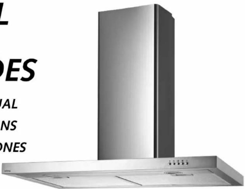

EXAUSTOR
Built-in Exhauster | Campana Inscrustación | Exhauster Encastre
ORC-1003-C
SERVIÇO DE APOIO AO CLIENTE
Apoio ao Cliente:
Tel.: (+351) 231 467 436 E: apoiocliente@orima.pt
Serviço Pós Venda:
Tel.: (+351) 231 467 427 E: assistencia@orima.pt
UK Thank you for purchasing this ORIMA product. Please read this manual carefully before using the appliance.
natural_image
Technical line drawing of a mechanical component with directional arrows, labeled Fig.6 (no text or symbols on the diagram itself)Fig.4 Fig.5
(3). Instalação
4 - Exaustor Tradicional
natural_image
Line drawing of a kitchen air conditioner with a lid and heat exchanger (no text or symbols)FIG6A

Botões
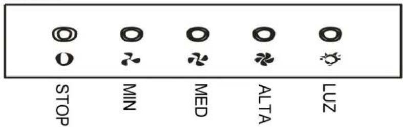
FIG6C
natural_image
Empty rectangular frame with gray border (no text or symbols)VISOR DIGITAL

MENOS/PARAR

MAIS/LIGAR
(1).....Notice
(2)....Feature
(3)....Installation
(4)....Air education setting
(5).....Notice of installation
(6)....Safety Warning
(7).....Use
(8)....Maintenance
(9)......Abnormity and Solution
(10)......Warranty card
(1) NOTICE
- Thank you for choosing our cooker hood. Please read the instruction manual carefully before use.
- The installation work must be undertaken by a qualified and competent fitter.
- The manufacturer disclaims all liability for any damage or injury caused as a result of not following instructions for installation contained in the following text.
The cooker hood is used on 220/240v, 50Hz.
(2)FEATURE
- The cooker hood uses high quality materials, and is made with a streamlined design.
- Equipped with a large power low noise electric motor and centrifugal leaf, it produces strong suction, low noise, non stick grease filter and easy to clean.
- With the isolated low voltage circuit board control, 12vDC input, the lights are therefore safer.
- Special wind tunnel construction and oil collector design, free dirt will be absorbed in a second.
(3). Installation
Product one:
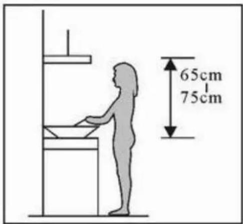
3.1 The cooker hood should be placed at a distance of 65-75cm(26-30inch) from the cooking surface to the best effect. See the Pic 1.
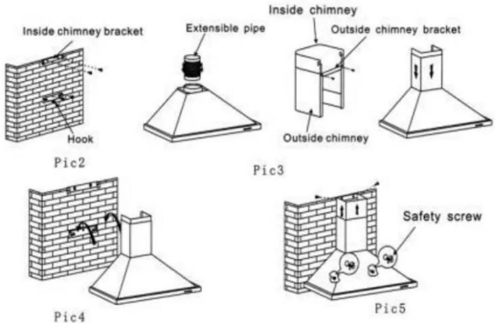
3.2 Install the hook on a suitable place once the installation height is fixed, and keep it in line. The fixed position of the inside chimney bracket is to place of chimney.
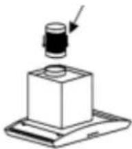
3.3 Fix the outside chimney bracket on the outs chimney, and be sure that the inside chimney car adjusted the height in in freely as well as fixing extensible pipe. Afterwards, install the extensible pipe and chimney on the cooker hood. See Pic 3
3.4 Put the cooker hood on the hook.See Pic 4.
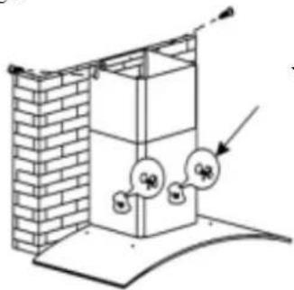
3.5 Adjust the height of the inside chimney to the position of the inside chimney bracket and fix on it by screw, after adjusting the position, fix the body with safety screw, See Pic 5.
Note: The two safety vents are positioned on the back casing, with diameter of 6mm.

Pic1
(3). Installation Product two(glass canopy):
3.1 The cooker hood should be placed at a distance of 65-75cm(26-30inch) from the cooking surface to the best effect. See the Pic. 1.
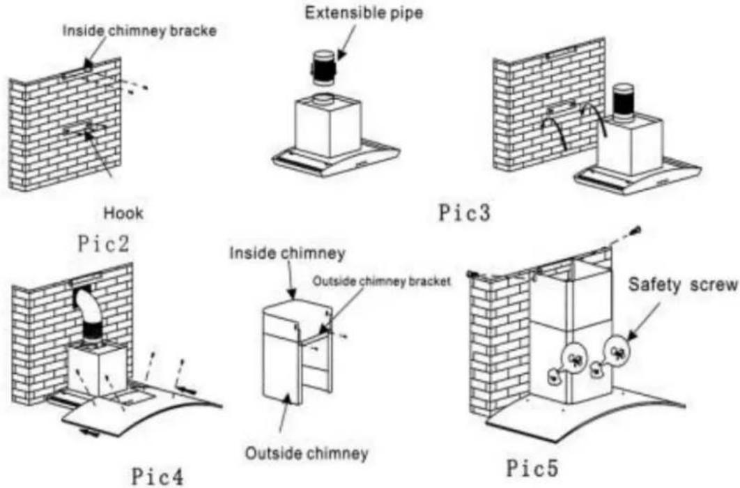
3.2 Install the hook on a suitable place once the installation height is fixed, and keep it in line. The fixed position of the inside chimney bracket is to place of chimney.
3.3 Fix the extensible pipe according to the lead direction and way, and then put the cooker hood the hook. See Pic 3.
3.4 Put the glass according to the lead direction way on the cooker hood, and then use the screw fix the glass, also lead the extensible pipe outside the room, meanwhile adjust the height of the insi chimney to the position of the inside chimney
Pic1
bracket and fix on it by screw, here should be sure the inside chimney can be flexed freely. See Pic 4.
3.5 Put the two chimneys together onto the cooker hood body, meanwhile adjust the height of the inside chimney into the suitable height, and fix the inside chimney to the inside chimney bracket by screw. Finally, fix the body with safety screw. See Pic 5.
Note: The two safety vents are positioned on the back casing, with diameter of 6mm.
(3). Installation
Product three( island):
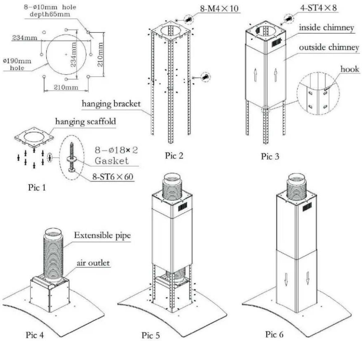
3.1 Make sure of installation position, fix the hanging scaffold at proper position, and check firmness and smoothness of installation. See the pic 1.
3.2 Adjst to proper height, joint the bracket, install on hanging scaffold. See the pic 2.
3.3 Fix inside chimney on hanging scaffold, enclose outside chimney on it at proper position, insert hook into bracket to fix outside chimney temporarily. See the pic 3.
3.4 Fix air outlet in the vent on hood's body, connect extensible pipe with air outlet. See the pic 4.
3.5 Extend the hose out off hanging scaffold, fix hood's body on bracket. See the pic5.
3.6 Detach the hook, move outside chimney downward till reaching hood's body. Pay attention not to strike the glass. See the pic 6.
(3). Installation
Product four(conventional type):
**install way one**
3.1 Place at a distance of 65-75cm from the cooking surface, drill 4 holes of 8mm and depth of 40mm .
3.2 Insert 4 swelling rubber plug into 4 holes.
3.3 Fix air outlet into the vent on top of the hood.
3.4 Open filters, keep the hood in line and tighten the screws.
3.5 Fix filters.
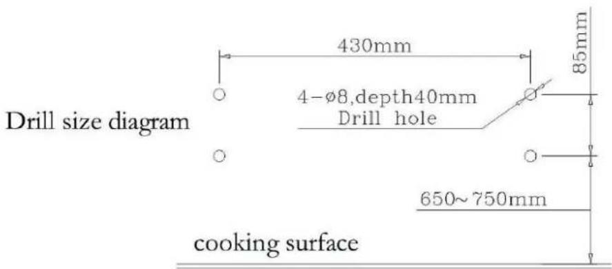
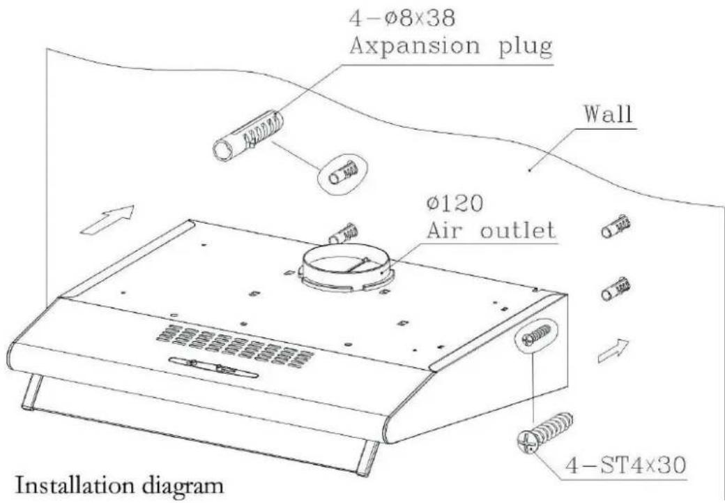
(3). Installation
Product four(conventional type):
**install way two**
3.1 Drill 4 holes ofΦ5mm andΦ130mm at the bottom of the hanging cupboard.
3.2 Fix air outlet into the vent on top of the hood.
3.3 Open filters, keep the hood in line, insert screws and swelling rubber plug, tighten the screws.
3.4 Fix filters.
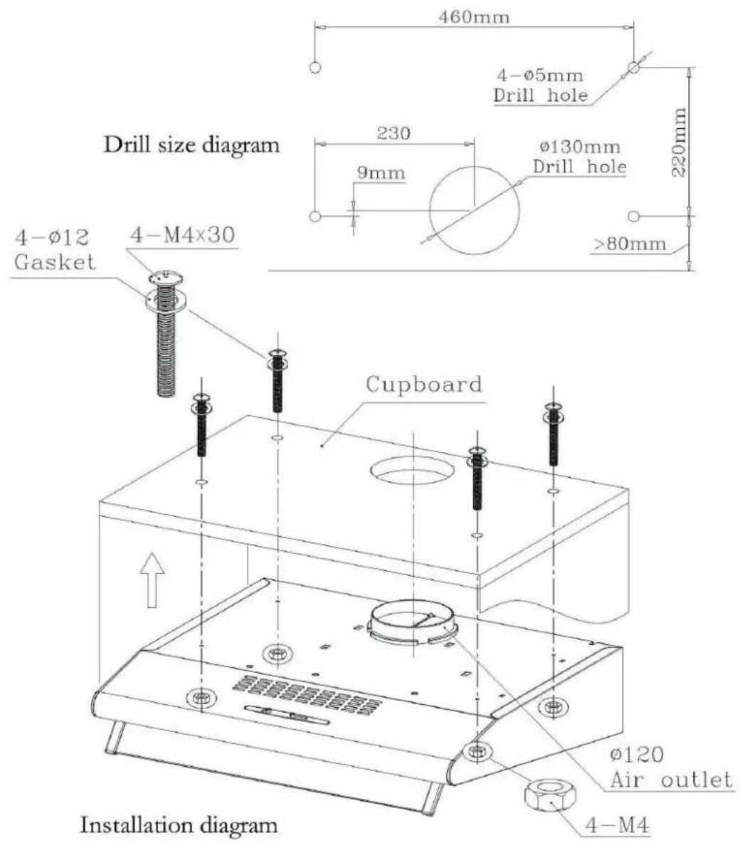
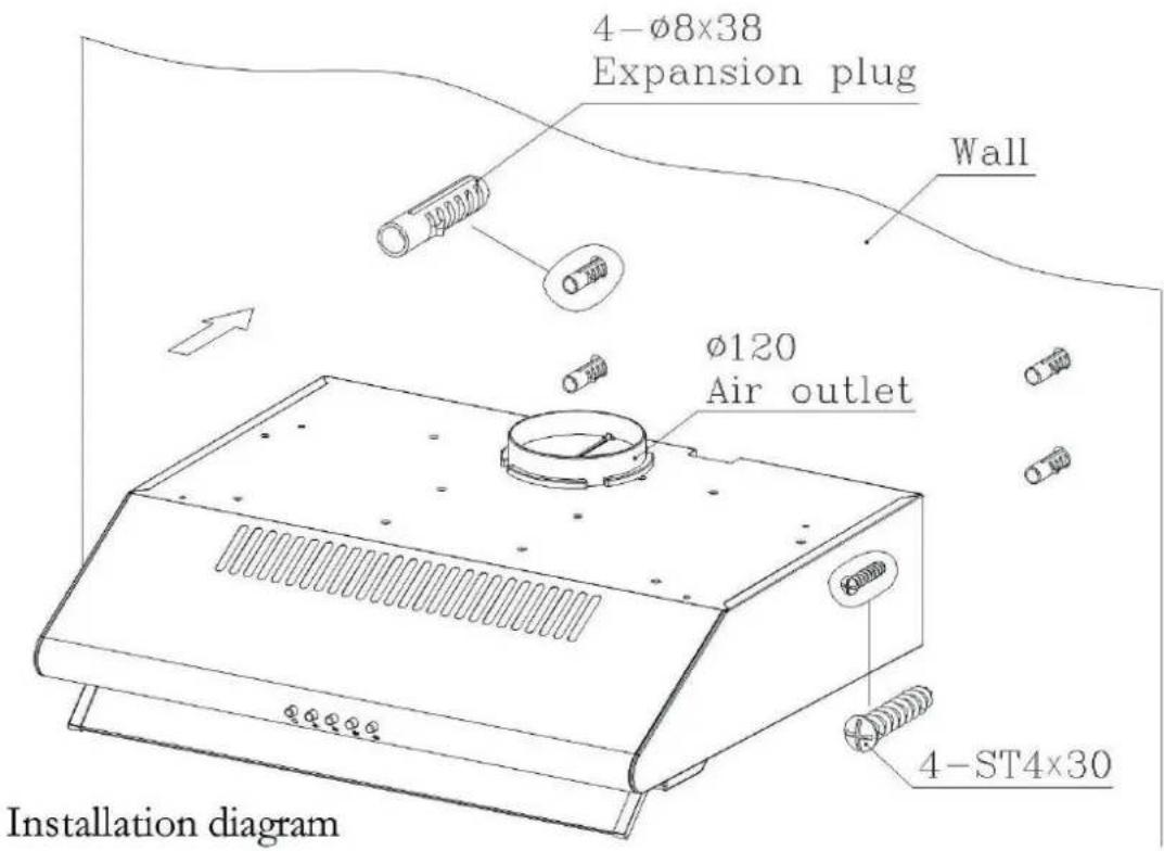
(3). Installation
Product five:
**install way one**
3.1 Place at a distance of 65-75cm from the cooking surface, drill 4 holes of Φ8mm and depth of 40mm.
3.2 Insert 4 swelling rubber plug into 4 holes.
3.3 Fix air outlet into the vent on top of the hood.
3.4 Open filters, keep the hood in line and tighten the screws.
3.5 Fix filters.
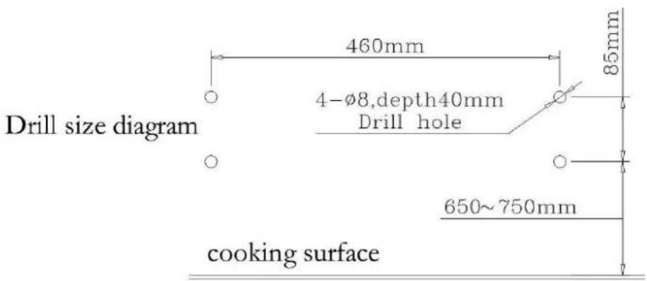
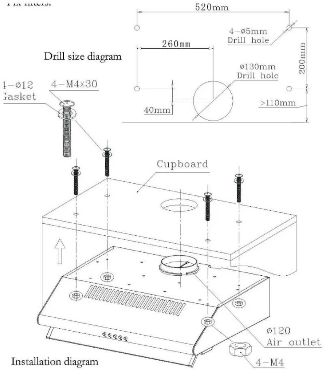
(3). Installation
Product five
\*\*install way two\*\*
3.1 Drill 4 holes of 5mm and 130mm at the bottom of the hanging cupboard.
3.2 Fix air outlet into the vent on top of the hood.
3.3 Open filters, keep the hood in line, insert screws and swelling rubber plug, tighten the screws.
3.4 Fix filters.
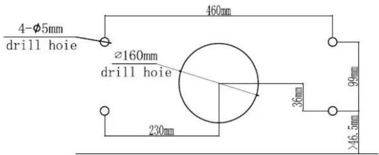
(3). Installation
Product six
3.1 Drill 4 holes 5mm and 130mm at the bottom of the hanging cupboard.
3.2 Fix air outlet into the vent on top of the hood.
3.3 Open filters, keep the hood in line, insert screws and swelling rubber plug, tighten the screws.
3.4 Fix filters.
Drill size diagram
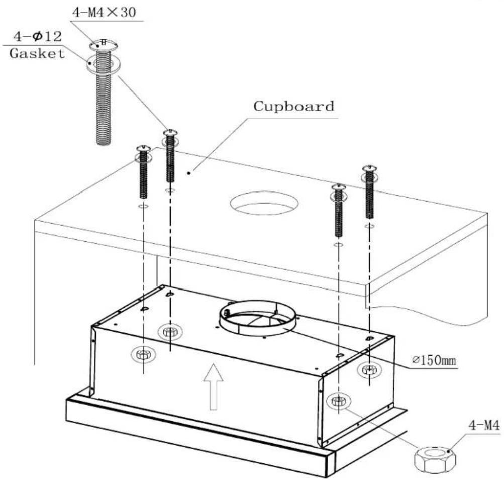
Installation diagram
(4). Air education setting
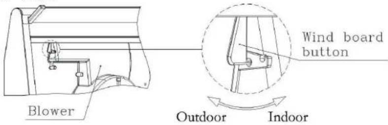
Product one:
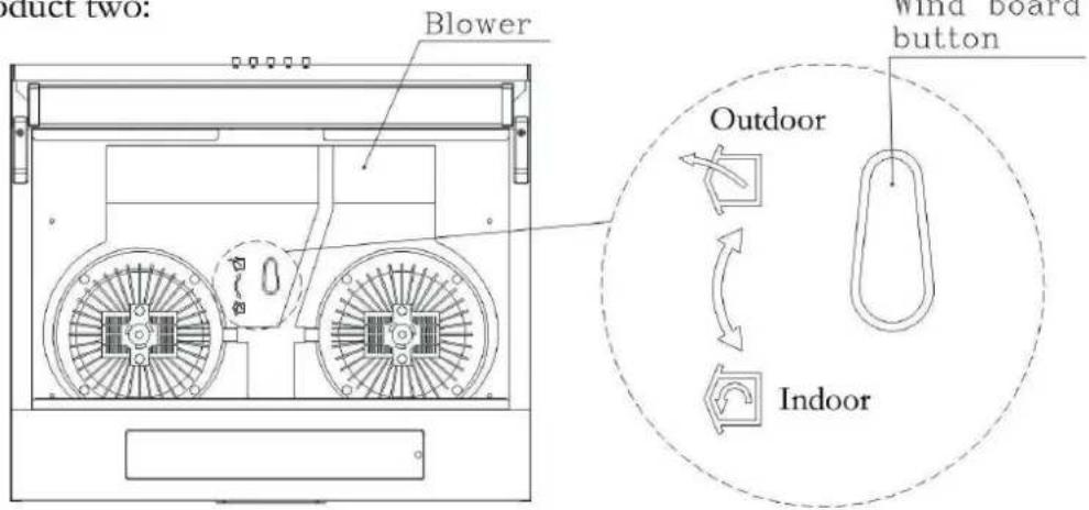
Product two:
natural_image
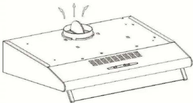
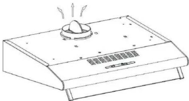
Line drawing of a kitchen fan with a lid and heat exchanger (no text or symbols)Setting one: Turn the adjuster to outdoor place, install the outlet, open the cooker hood, the smoke will be vented from the outside outlet.
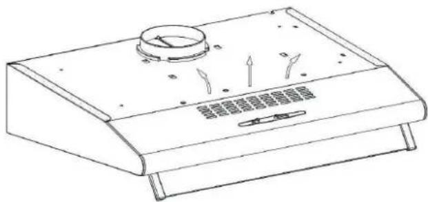
Setting two: Turn the adjuster to indoor to indoor place, install the outlet cover, open the cooker hood, the smoker will be vented from inside vent.
---- Warning: Failure to install the screws or fixing device in accordance with these instructions may result in electrical hazards.
(5) NOTICE OF INSTALLATION
-
Before installation, please ensure the area is clean to avoid suction of the remaining bits of broken wood and dust.
-
It cannot share the same air ventilation tube with other appliance such as gas tube, warmer tube, and hot wind tube.
-
The bending of ventilation tube should ≥slant 120^ , parallel or above the start point and should be connected to the external wall.
-
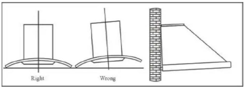
After installation, make sure that the extractor is level to avoid grease collection at one end.
Pic5
(6) SAFETY WARNING
- Never let the children operate the machine.
- The cooker hood is for home use only, not suitable for barbecue, roast shop and other commercial purpose.
- The cooker hood and its filter should be clean regularly in order to keep in good working condition.
- Clean the cooker hood according to the instruction manual and keep the unit from danger of burning.
- Forbid the direct baking from the gas cooker.
- Please keep the kitchen room a good convection.
- Before connecting this appliance check that the power supply cord is not damaged. A damage supply cord must be replaced by qualified service personnel only.
- There shall be adequate ventilation of the room when the range hood is used at the same time as appliances burning gas or other fuels
- The air must not be discharged into a flue that is used for exhausting fumes from appliances burning gas or other fuels
- Regulations concerning the discharge of air have to be fulfilled.
- This appliance if not intended for use by persons(including children) with reduced physical, sensory or mental capabilities, or lack of experience and knowledge, unless they have been given supervision or instruction concerning use of the appliance by a person slide for their safety.
- Children should be supervised to ensure that they do not play with the appliance.
- Do not flambé under the range hood.
- The range hood is not intended to be installed over a hob having more than four hob elements
- This appliance is not intended for use by persons (including children) with reduced physical, sensory or mental capabilities, or lack of experience and knowledge, unless they have been given supervision or instruction concerning use of the appliance by a person responsible for their safety.
- Children should be supervised to ensure that they do not play with the appliance.
- The air must not be discharged into a flue that is used for exhausting fumes from appliances burning gas or other fuels.
- When the range hood and appliances supplied with energy other than electricity are simultaneously in operation, the negative pressure in the room must not exceed 4 Pa (4 x 10⁻⁵ bar).
- CAUTION: Accessible parts may become hot when used with cooking appliances.
Electrical Shock Hazard
- Only plug this unit into a properly earthed outlet. If in doubt seek advice from a suitably qualified engineer.
● Failure to follow these instructions can result in death, fire, or electrical shock.
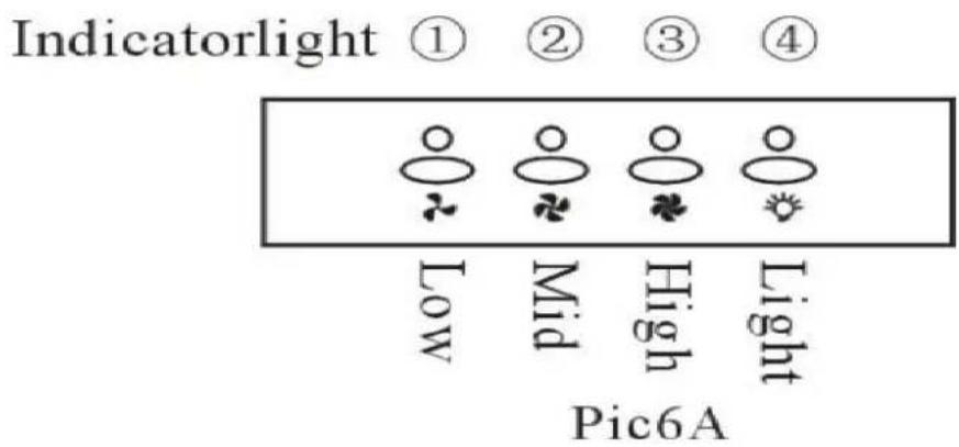
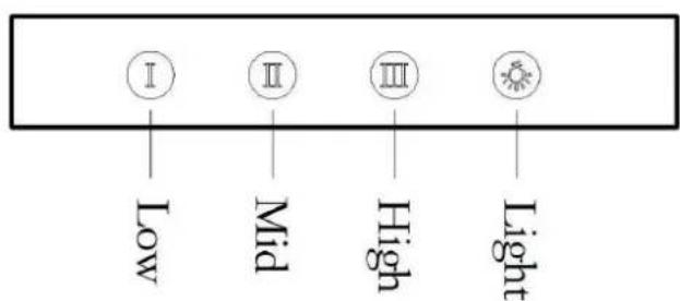
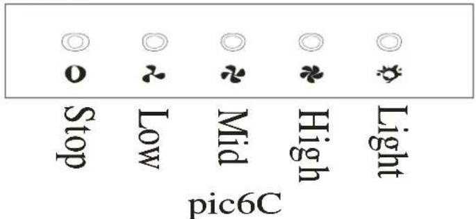
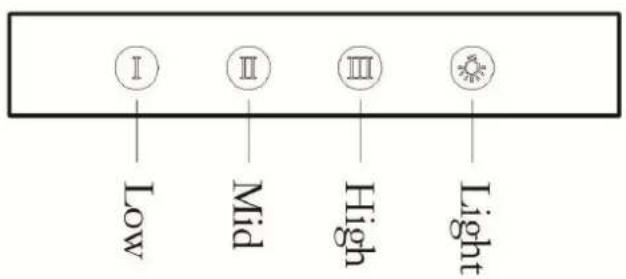
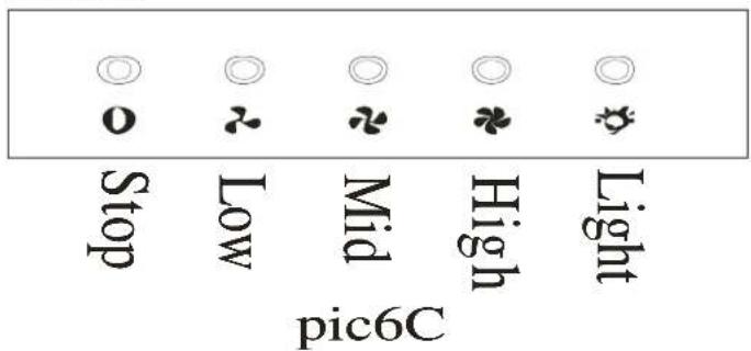
(7) USE (Speed adjustment .See pictures)
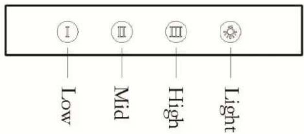
Electronic Button
- Turn on the power; the buzzer will buzz five times. The sound shows that the appliance is powered.
- Push the low button, the indicating light 1 on, the buzzer will buzz once, and the motor runs at low speed. Push it again and the motor will stop.
- Push the middle button, the indicating light 2 on, the buzzer will buzz once, and the motor runs at mid speed. Push it again and the motor will stop
- Push the high button, the indicating light 3 on, the buzzer will buzz once, and motor runs on high speed. Push it again and the motor will stop
- Push the light button; the indicating light 4 on, and the two lighting lamps will come on. Push it again and the lamps will turn off, with every push the buzzer will buzz one time.
Push button
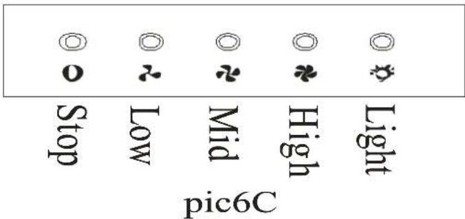
- Push stop button, and the motor will stop.
- Push the Low button, the buzzer will buzz once, and the motor runs at low speed.
- Push the high button, the buzzer will buzz once, and the motor runs at mid speed.
- Push the High button, the buzzer will buzz once, and the motor runs at high speed.
- Push the light button and the two lights will come on. Push it again and the light will turn off.
Push Slide Switch:
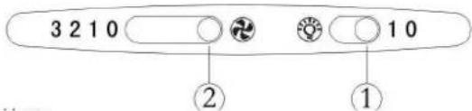
- "lighting" button
Used to connect or cut off the lighting lamp.
- " three-range fan speed" sliding button
Used to set the low-range, medium range and high range rotation speed and ventilation of the fan.
The instruction is only suitable for slim hood.
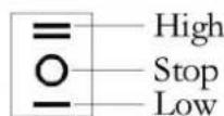
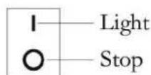
Rocker Switch:
- motor switch
- lamp switch
- motor switch
is with a high and a low speed, the middle is stop button
- lamp switch
control the lamp on or off.
Touch control switch No. one:
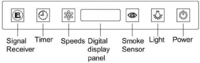
Touch control switch No. two:
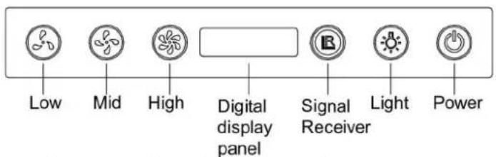
Touch control switch No. three:





Digital display panel
- ☐ The signal receiver by remote control.
- Timer, which can set from one minute to 60 minutes.
- Speeds, which can be adjustable by sequence from high speed, to mid and to low until the motor stops running.
- Smoke sensor which can detect the fumes and get the motor start to absorb the fumes by automatically when it's powered on.
- Light on/off.
- Power off.
- Touch one time, it will time one minute to turn off the power, Touch twice successively, it will turn the power off directly.
- ✅ Speed adding from low to mid, and to high by sequence.
- ⊖ Speed descending by sequence from high to mid, and to low until the power stops running.
(8) MAINTENANCE
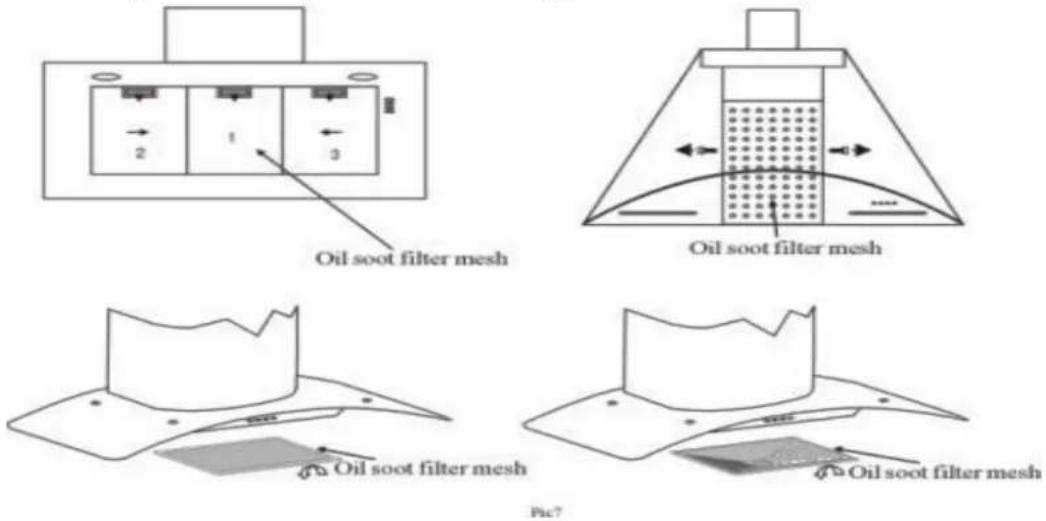
8.1 The cleaning of the carbon grease filter mesh
The filter mesh is made of high-density stainless steel. Please do not use the corrosive detergent on it. Keeping this filter clean will keep the appliance running correctly. Please strictly follow the guidelines below.
Method 1: Put the mesh into 40-50 c clean water, pour on detergent, and soak for 2-3 mins. Wear gloves and clean with a soft brush. Please do not apply too much pressure, as the mesh is delicate and will damage easy.
Method 2: If instructed to do so, it can be put into a dishwasher, set the temperature at around 60 degrees.
8.2 Notice of cleaning cooker hood
A. To protect the main body from corrosion over a long period of time, the cooker hood should be cleaned with hot water plus non corrosive detergent every two months.
B. Please do not use abrasive detergent for it will damage the body.
C. Keep the motor and other spare parts free from water, as this will cause damage to the appliance.
D. Before cleaning the appliance please remember to cut off power
E. The carbon filter shouldn't be exposed to heat.
F. Please don't tear open the fixed bar around the carbon filter
G. If the plug or cord is damaged, please replace it with special soft cord.
(9). Abnormity and Solution
| Fault | Cause Solution | ||
| Light on, but motor does not work | The leaf blocked Get rid of the blocking | ||
| The capacitor damaged Replace | capacitor | ||
| The motor jammed bearing damaged | Replace motor | ||
| The internal with of motor off a bad smell from the motor | Replace motor | ||
| Light does not work, motor does not work | Beside the above mentioned, check the following: | ||
| Light damaged Replace lights | |||
| Power cord looses Connect the wires as per the electric digram | |||
| Oil leakage | One way valve and the air ventilation entrance are not tightly sealed | Take down the one way valve and seal with glue | |
| Leakage from the connection of U-shaped section and cover | Take U-shaped section down and seal with soap or paint | ||
| Shake of the body The leaf damaged and causes shaking | Replace the leaf | ||
| Lock the motor tightly | |||
| Fixed the body tightly | |||
| Insufficient suction The distance between the body and the gas top too long | Readjust the distance | ||
| Choose a new place and resemble the machine | |||
| The machine inclines | The fixing screw not tight enough | Tighten the hanging screw and make it horizontal | |
| The hanging screw not tight enough | Tighten the hanging screw and make it horizontal | ||
(10.) Warranty Card
We will warrant this product free from defects in material and quality for one year from date of purchase. If any problems occur from correct usage, please contact the service department for under warranty service.
This warranty does not cover the following:
The filter mesh and bulb.
Commercial use.
Amendment of the date of manufacture on the rating plate.
After 24 months from date of purchase. Damaged caused to the body by usage of detergent sprayer. Pollution made to the led parts, glass parts and S/S parts. Incorrect installation, misuse, abuse or neglect.
Incorrectly fitted to insufficient or unsuitable power. Damage caused by foreign object.
Taken apart or serviced by unauthorized service engineers or replaced with other manufacture's components.
For commercial use the maintenance and free service should be discussed with our authorized agent.
Beyond the 24 months warranty period, the purchaser should pay for charge of components and call out.
In the event of a service call, please provide the warranty card and receipt of date of purchase.
Place of
purchase
Date of
purchase
Model
Shop
stamp.
Exhaustor
Pic6A
Botones
natural_image
Diagram of a person standing on a brick wall next to a box, with no visible text or symbolsFig.4
Conduit extensible
natural_image
Simple line drawing of a mechanical component with a cylindrical top and base, no text or symbols present.natural_image
Illustration of a brick wall with a mounted device and a separate brick block (no text or symbols)Fig.3
natural_image
Diagram of a brick wall structure with two circular components and an arrow pointing to one (no text or symbols)Fig.5
(6) CONSIGNES DE SÉCURITÉ
Pic6A
Boutons
natural_image
Simple line drawing of a mechanical component with no text or symbols


- MANUAL DE INSTRUÇÕES
- EXAUSTOR
- SERVIÇO DE APOIO AO CLIENTE
- (3). Instalação
- - Exaustor Tradicional
- Botões
- NOTICE
- (2)FEATURE
- (3). Installation
- Product one:
- (3). Installation Product two(glass canopy):
- Product three( island):
- Product five
- \*\*install way two\*\*
- Product six
- (4). Air education setting
- NOTICE OF INSTALLATION
- SAFETY WARNING
- Electrical Shock Hazard
- USE (Speed adjustment .See pictures)
- Electronic Button
- Push button
- Push Slide Switch:
- Rocker Switch:
- MAINTENANCE
- The cleaning of the carbon grease filter mesh
- Notice of cleaning cooker hood
- (9). Abnormity and Solution
- (10.) Warranty Card
- Exhaustor
- Botones
- CONSIGNES DE SÉCURITÉ
- Boutons
Brand : Orima
Model : ORC 1003 C
Category : Range hood