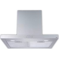
ORC60630T - Range hood Orima - Free user manual and instructions
Find the device manual for free ORC60630T Orima in PDF.


| Product type | Decorative chimney hood |
| Brand | Orima |
| Model | ORC60630T |
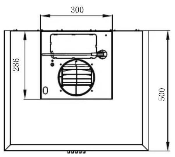
| Dimensions (H x W x D) | 475-810 mm (adjustable) x 600 mm x 500 mm |
| Estimated net weight | 12 kg |
| Color | Stainless steel |
| Power supply | 220-240 V ~ 50 Hz |
| Motor power | 200 W (estimated) |
| Noise level | 55 dB (estimated) |
| Airflow rate | 600 m³/h (estimated) |
| Installation type | Ducted or recirculating (with optional carbon filter) |
| Duct diameter | 120 mm or 150 mm (depending on supplied flange) |
| Number of speeds | 3 (low, medium, high) |
| Lighting | LED, max. 1.5 W |
| Grease filters | Metal, dishwasher safe (every 2 months) |
| Carbon filter | Optional, replaceable (every 4 months) |
| Minimum distance above cooktop | 650 mm |
| Package contents | Hood, upper and lower decorative chimney, flange, duct, grease filters, carbon filters (optional), brackets, screws, instruction manual |
| Main functions | Motor stop, speed control, lighting |
| Safety | Mandatory grounding, safety distance, motor stop |
Frequently Asked Questions - ORC60630T Orima
User questions about ORC60630T Orima
0 question about this device. Answer the ones you know or ask your own.
Ask a new question about this device
Download the instructions for your Range hood in PDF format for free! Find your manual ORC60630T - Orima and take your electronic device back in hand. On this page are published all the documents necessary for the use of your device. ORC60630T by Orima.
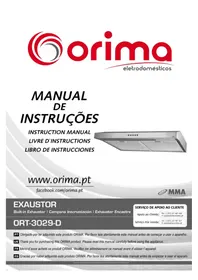
USER MANUAL ORC60630T Orima
natural_image
Abstract spiral graphic with concentric curved lines (no text or symbols)orima
eletrodomésticos
MANUAL DE INSTRUÇÕES
INSTRUCTION MANUAL LIVRE D'INSTRUCTIONS LIBRO DE INSTRUCCIONES
natural_image
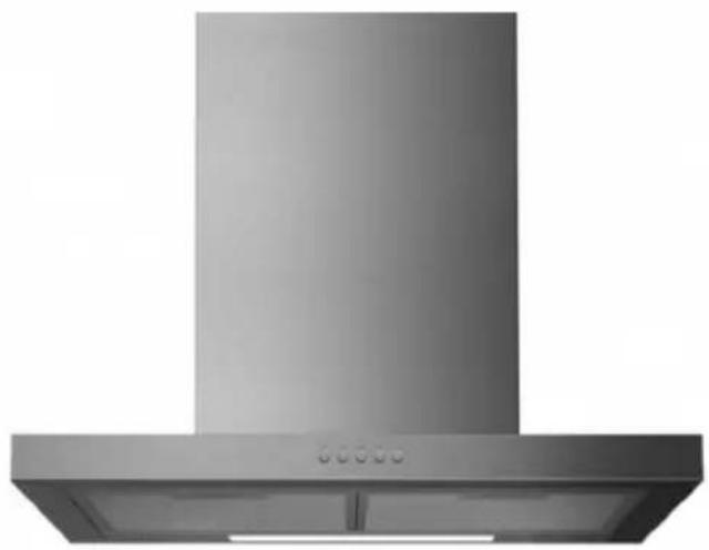
Exterior view of a stainless steel kitchen range hood (no text or symbols visible)www.orima.pt
facebook.com/orima.pt

MMA
Exaustor
Range hood / Campana extractora / Hotte de cuisinié
ORC 60630 T
SERVIÇO DE APOIO AO CLIENTE
Apoio ao Cliente:
Tel.: (+351) 231 467 436
natural_image
Illustration of a kitchen range hood with a steaming lamp and a control panel (no text or symbols)MODO DE UTILIZAÇÃO
natural_image
Simple line drawing of a house with fire and smoke, no text or symbols presentnatural_image
Pure technical line drawing of two mechanical components with no text or symbols| Opção | Chaminé | X | Y |
| 1 | 400X390 | 129 | 50-350 |
| 2 | 500X490 | 229 | 50-450 |
| 3 | 560X560 | 289 | 50-520 |
Fixador C
natural_image
Simple line drawing of a T-shaped object with a vertical dashed line and circular markers at the base (no text or symbols)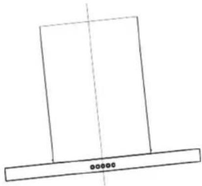
natural_image
Simple line drawing of a rectangular frame with a vertical centerline and a horizontal base (no text or symbols)Correto Incorreto
LIGAÇÕES
UTILIZAÇÃO
natural_image
Five circular icons with symbols: one with a leaf, three with crescent and star, two with a sun, and one with a crescent and arrow (no text or labels)natural_image
Hand pointing at a smartphone screen with a download arrow (no text or symbols visible)natural_image
Technical line drawing of a mechanical assembly with a hand holding a tool (no text or symbols)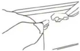
natural_image
Line drawing of two hands holding a rectangular object, no text or symbols present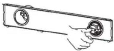
natural_image
Hand inserting a circular component into a rectangular device (no text or symbols visible)natural_image
Abstract spiral design with concentric curved lines (no text or symbols)orima
eletrodomésticos
MANUAL DE INSTRUÇÕES
INSTRUCTION MANUAL LIVRE D'INSTRUCTIONS LIBRO DE INSTRUCCIONES
natural_image
Exterior view of a stainless steel kitchen range hood (no text or symbols visible)www.orima.pt
facebook.com/orima.pt

MMA
MÁRIO MELANCA DE ALMEIDA
Exaustor
Range hood / Campana extractora / Hotte de cuisinière
ORC 60630 T
SERVIÇO DE APOIO AO CLIENTE
Apoio ao Cliente:
Tel.: (+351) 231 467 436 E: apaioclientes@orima.pt
Serviço Pós Venda:
Tel.: (+351) 231 467 427 E: assistencia@orima.pt
PT Obrigado por ter adquirido este produto ORIMA. Por favor leia atentamente este manual antes de começar a usar o aparelho.
UK Thank you for purchasing this ORIMA product. Please read this manual carefully before using the appliance.
FR Merci d'avoir acheté ce produit ORIMA. Veuillez lire attentivement ce manuel avant d'utiliser l'appareil.
ES Gracias por haber adquirido este produto ORIMA. Por favor lea atentamente este manual antes de empezar a usar el aparato.

The instructions for Use apply to several versions of this appliance. Accordingly, you
may find descriptions of individual features that do not apply to your specific appliance.
INSTALLATION
● The manufacturer will not be held liable for any damages resulting from incorrect or improper installation.
- The minimum distance between the supporting surface for the cooking vessels on the hob and the lowest part of the range hood. ( When the range hood is located above a gas appliance, this distance shall be at least 65 cm. If the instructions for installation for the gas hob specify a greater distance, this has to be taken into account. The distance of 65 cm can be reduced for:non-combustible parts of range hoods, and parts operating at safety extra low voltage,Provided these parts do not give access to live parts if deformed;)
- Check that the mains voltage corresponds to that indicated on the rating plate fixed to the hood.
- For Class I appliances, check that the domestic power supply guarantees adequate earthing.
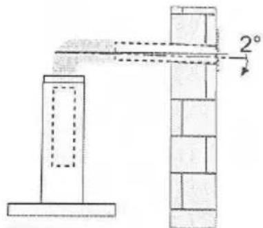
- Connect the extractor to the exhaust flue through a pipe of minimum diameter 120mm. The route of the flue must be as short as possible.
● The air must not be discharged into a flue that is used for exhausting fumes from appliances burning gas or other fuels.
- If the extractor is used in conjunction with non-electrical appliances (e.g. gas burning appliances), a sufficient degree of aeration must be guaranteed in the room in order to prevent the backflow of exhaust gas. The kitchen must have an opening communicating directly with the open air in order to guarantee the entry of clean air. When the cooker hood is used in conjunction with appliances supplied with energy other than electric, the negative pressure in the room must not exceed 0.04 mbar to prevent fumes being drawn back into the room by the cooker hood.
D If the supply cord is damaged, it must be replaced by the manufacturer, its service agent or similarly qualified persons in order to avoid a hazard.
● Regulations concerning the discharge of air have to be fulfilled.
natural_image
Simple line drawing of a kitchen appliance with a funnel and fan, emitting steam from a pot (no text or symbols)USE
D The cooker hood is only for home use, not suitable for barbecue, roast shop and other commercial purposes.
● Never use the hood for purposes other than for which it has been designed.
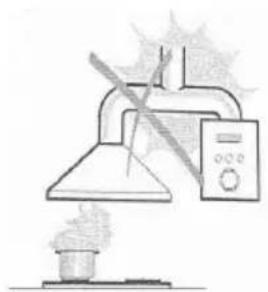
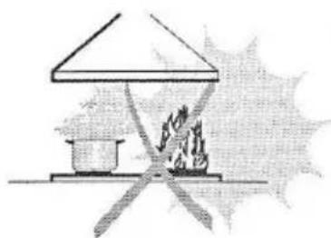
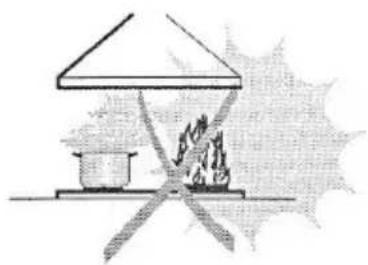
● Never leave high naked flames under the hood when it is in operation.
- Adjust the flame intensity to direct it onto the bottom of the pan only, making sure that it does not engulf the sides.
- Deep fat fryers must be continuously monitored during use: overheated oil can burst into flames.
● Do not flame under the range hood; risk of fire.
● This appliance can be used by children aged from 8 years and above and persons with reduced physical, sensory or mental capabilities or lack of experience and knowledge if they have been given supervision or instruction concerning use of the appliance in a safe way and understand the hazards involved.
● Children should be supervised to ensure that they do not play with the appliance.
● Cleaning and user maintenance shall not be made by children without supervision.
● "CAUTION: Accessible parts may become hot when used with cooking appliances".
MAINTENANCE
● The cooker hood and its filter should be cleaned regularly according to the instruction.
- Switch off or unplug the appliance from the mains supply before carrying out any maintenance work.
● Clean and/or replace the Filters after the specified period (Fire hazard).
● Clean the hood using a damp cloth and a neutral liquid detergent.
● The appliance uses 4 hob elements at most.

natural_image
Simple line drawing of a house with a chimney and fire, no text or symbols presentThe symbol is packaging indicates that this product may not be treated as household waste. Instead it shall be handed over to the applicable collection point for the recycling of electrical and electronic equipment. By ensuring this product is disposed of correctly, you will help prevent potential negative consequences for the environment and human health, which could otherwise be caused by inappropriate waste handling of this product. For more detailed information about recycling of this product, please contact your local city office, your household waste disposal service or the shop where you purchased the product.
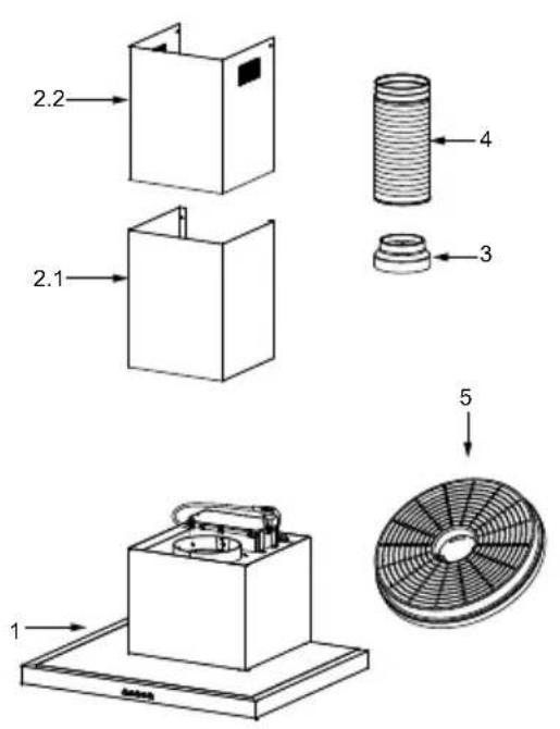
| Ref. Qty. Product Components | |
| 1 | 1 Hood Body, complete with: Controls, Light, Blower, Filter. |
| 2.1 1 | Lower Decorative Chimney |
| 2.2 1 | Upper Decorative Chimney |
| 3 | 1 Flange (optional) |
| 4 | 1 Exhaust Pipe |
| 5 | 2 The Activated Charcoal filter (optional) |
| Qty. | Documentation |
| 1 | Instruction Manual |
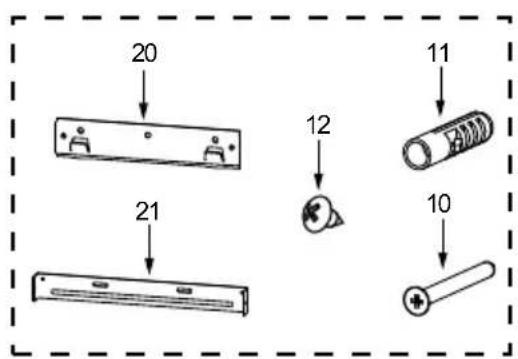
| Ref. | Qty. | Installation Components |
| 10 | 7 | Screws 5 x 50 |
| 11 7 | Wall Plugs10x42 | |
| 12 6 | Screws 4,2 x 9,5 | |
| 20 1 | Hood fixing bracket | |
| 21 2 | Chimney fixing bracket |
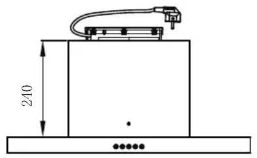
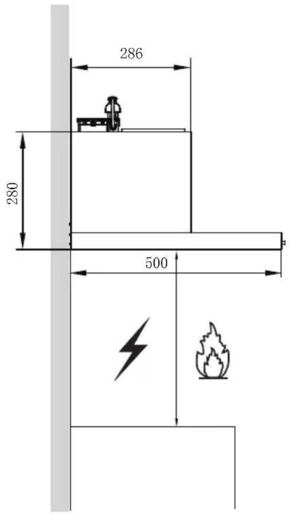

| Option | Chimney | A | B |
| 1 | 400+390 | 440 | 475-810 |
| 2 | 500+490 | 540 | 575-1010 |
| 3 | 560+560 | 600 | 635-1140 |
natural_image
Pure technical line drawing of two mechanical brackets with mounting holes and no text or symbols| Option | Chimney | X Y | |
| 1 400 | X390 | 129 | 50-350 |
| 2 500 | X490 | 229 | 50-450 |
| 3 560 | X560 | 289 | 50-520 |
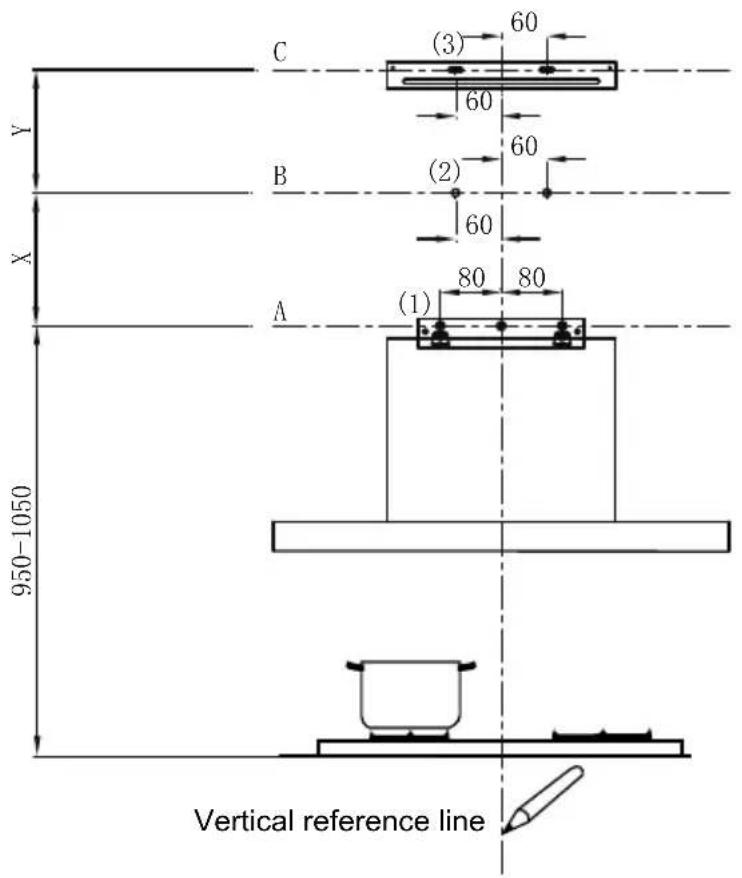
As a first step, proceed with the following drawings:
- A vertical line up to the ceiling or up to the upper limit, at the center of the area in which the hood is to be fitted.
● A horizontal line A at 950 – 1050 mm above the cooker top.
● A horizontal line B at a X mm above the horizontal line A.
● A horizontal line C at a Y mm above the horizontal line B.
Mark Points:
● Mark a point (1) on the horizontal line A, 80 mm to the vertical reference line.
- Repeat this operation on the other side and on the vertical reference line, checking that the three marks are leveled.
● Mark a point (2) on the horizontal line B, 60 mm to the vertical reference line.
- Repeat this operation on the other side, checking that the two marks are leveled.
- Mark a point (3) on the horizontal line C, 60 mm to the vertical reference line. Repeat this operation on the other side, checking that the two marks are leveled.
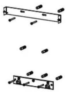
Fix the brackets :
- Drill holes at the marked points with a 10 mm drill bit.
- Insert the Wall Plugs 11 into the holes.
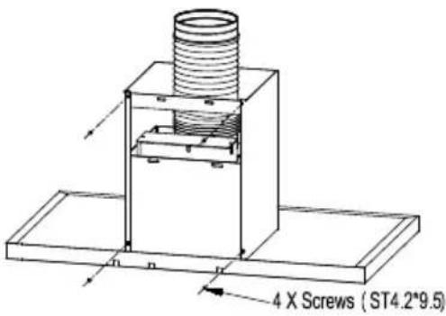
● Fix a Chimney fixing bracket 21 with 2 screws 10 (5 x 50) at the horizontal line C.
Lower decorative chimney
● Fix the exhaust pipe on the hood body, connect chimney and hood body with 2 screws 12. connect chimney fixing bracket and chimney with 2 screws 12.
Hook the hood body
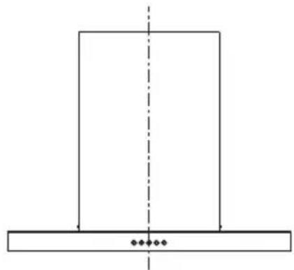
D Hook the hood body to the hood fixing bracket 20. Level the hood body itself.
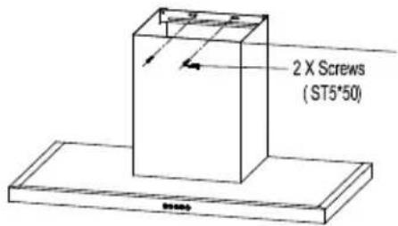
D Fix a Chimney fixing bracket 21 with 2 screws 10 (5 x 50) at the horizontal line B to prevent the hood body from accidentally sliding off the hood fixing bracket.

natural_image
Pure geometric diagram showing a rectangle with a vertical dashed line and a horizontal base, no text or symbols present.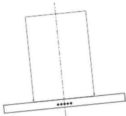
natural_image
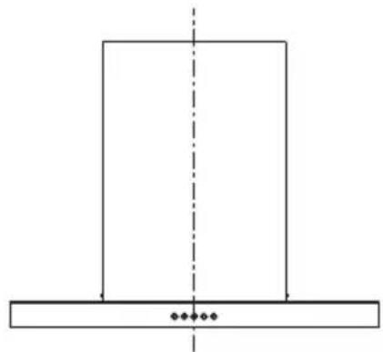
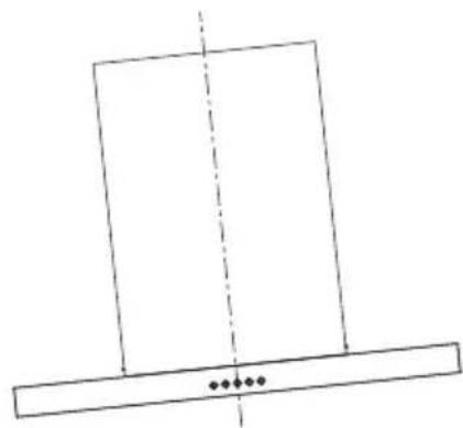
Simple line drawing of a rectangular frame with a vertical dashed line and three dots below (no text or symbols)Right Wrong
CONNECTIONS
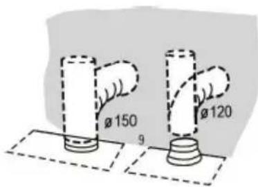
DUCTED VERSION AIR EXHAUST SYSTEM
When installing the ducted version, connect the hood to the chimney using either a flexible or rigid pipe 150 or 120 mm, the choice of which is left to the installer.
- If to install a 120 mm air exhaust connection, insert the reducer flange 3 on the hood body outlet.
● Fix the pi pe 4 in position using sufficient pipe clamps (not supplied). - Remove possible charcoal filters.
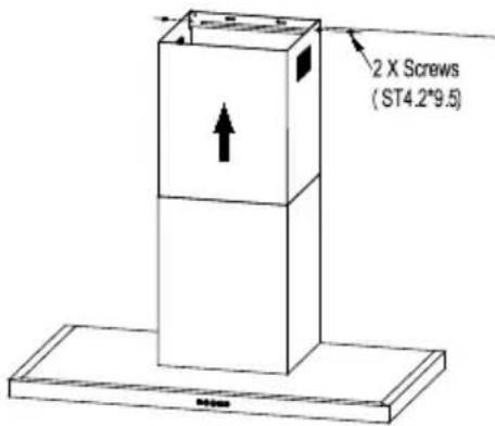
Upper Decorative Chimney
- Insert the upper decorative chimney 2.2 into the lower decorative chimney 2.1 and drag it up to the horizontal line C
● Connect upper decorative chimney 2.2 and chimney fixing bracket 21 with 2 screws 12.
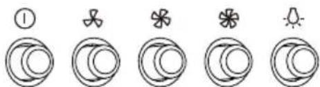
USE
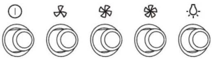
Speed adjustment.
natural_image
Five circular icons in sequence: one with a leaf and number 1, three with crescent shapes, two with stars, and one with sun (no text or symbols)| 1 | OFF MOTOR SWITCH: Press on this switch to stop the motor operation. |
| SPEED SWITCH: Press on this switch, the motor runs at LOW speed. | |
| SPEED SWITCH: Press on this switch, the motor runs at MEDIUM speed. | |
| SPEED SWITCH: Press on this switch, the motor runs at HIGH speed. | |
| ON/OFF LIGHTING SWITCH: Press on this switch to turn on the lights, and press again to turn them off. |
GREASE FILTERS
CLEANING METAL SELF-SUPPORTING GREASE FILTERS
- The filters must be cleaned every 2 months of operation, or more frequently for particularly heavy usage, and can be washed in a dishwasher.
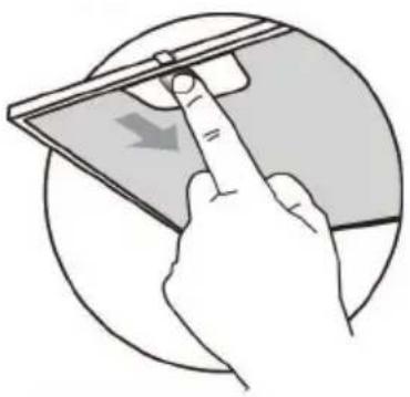
- Remove the filters one by one pushing them towards the back side of the hood unit and simultaneously pulling downwards.
- Any kind of bending of the filters has to be avoided when washing them. Before fitting them again into the hood make sure that they are completely dry. (The color of the filter surface may change throughout the time but this has no influence to the filter efficiency).
- When fitting the filters into the hood pay attention that they are mounted in correct position the handle facing outwards.
natural_image
Illustration of a hand using a smartphone to interact with a device, showing a finger pointing at the screen (no text or symbols present)ACTIVATED CHARCOAL FILTER (RECIRCULATION VERSION)
These filters are not washable and cannot be regenerated, and must be replaced approximately every 4 months of operation, or more frequently with heavy usage.
REPLACING THE ACTIVATED CHARCOAL FILTER
- Remove the metal grease filters
- Remove the saturated activated charcoal filter.
● Fit the new filters. - Replace the metal grease filters.
LIGHTING
LIGHT REPLACEMENT
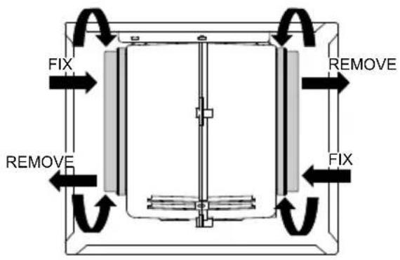
Dismantle LED light module
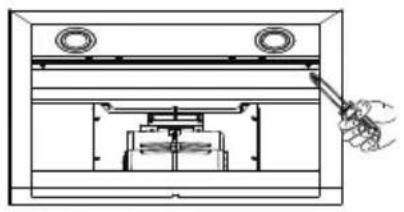
- Remove the grease filter and carefully remove the 2 screws from the front plate (a cross headed screwdriver will be needed to remove the screws).
- Disconnect the terminal of LED light.
- Press LED light on the back of the front plate, take the LED light out.
- Replace the lamp(commercially available LED lamp (max.1.5w).
natural_image
Technical line drawing of a mechanical assembly with no visible text or symbols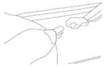
natural_image
Line drawing of a hand holding a small object, possibly a tool or device, with no visible text or symbols.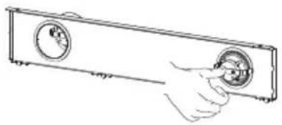
natural_image
Line drawing of a hand inserting a circular component into a rectangular device (no text or symbols)| Max Power | Voltage | Picture Lamp Cap ILCOS D code | |||
| Round/ Diameter : 70mm | 1.5W DC | 12 V | 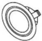 | —— | DSR-1.5-S-70 |
Reinstall LED light module
- Press LED light on the front of front plate, install the LED light on the front plate.
- Connect the terminal of LED light and light leads.
- Carefully fasten the 2 screws on the front plate, reinstall the grease filter.
| Fault | Cause | Solution |
| Light on, but motor does not work | The blades are blocked. | Check the blades. |
| The capacitor is damaged. | Replace capacitor. | |
| The motor is damaged. | Replace motor. | |
| The internal wiring of motor is cut off/disconnected. An unpleasant smell may be produced. | Replace motor. | |
| Both light and motor do not work | Apart from the above mentioned, check the following: | |
| Light damaged. | Replace lights. | |
| Power cord loose. | Connect the wires as the electric diagram. | |
| Oil leakage | Outlet and the air ventilation entrance are not tightly sealed. | Take down the outlet and seal with glue. |
| Vibration | The blade, if damaged, can cause vibrating. | Replace the blade. |
| The motor is not tightly fastened. Fasten the motor tightly. | ||
| The cooker hood is not tightly fixed. Fixed the cooker hood tightly. | ||
| Insufficient suction | The distance between the cooker hood and the cooker top is too large. | Readjust the distance. |
| Too much ventilation from open doors or windows. | Choose a new place to install the appliance or close some doors / windows. | |
| The machine inclines | The fixing screws are not tight enough. | Tighten the fixing screw and make it horizontal. |
| The hanging screws are not tight enough | Tighten the hanging screw and make it horizontal. | |
DISPOSAL OF OLD ELECTRICAL APPLIANCES


The European directive 2012/19/EU on Waste Electrical and Electronic Equipment (WEEE), requires that old household electrical appliances must not be disposed of in the normal unsorted municipal waste stream. Old appliances must be collected separately in order to optimize the recovery and recycling of the materials they contain, and reduce the impact on human health and the environment.
The crossed out “wheeled bin” symbol on the product reminds you of your obligation, that when you dispose of the appliance, it must be separately collected.
Consumers should contact their local authority or retailer for information concerning the correct disposal of their old appliance.
natural_image
Simple line drawing of a heating lamp with a control panel and smokestack (no text or symbols)natural_image
Simple line drawing of a house with a chimney and fire extinguisher, no text or symbols presentnatural_image
Symbol of a waste bin with no text or labels, crossed by two crossed lines and a solid black rectangle below (no text or symbols present)natural_image
Pure technical line drawing of a mechanical bracket assembly without any text, numbers, or symbols| Opción | Chimenea | X | Y |
| 1 400 | X390 | 129 | 50-350 |
| 2 500 | X490 | 229 | 50-450 |
| 3 560 | X560 | 289 | 50-520 |
natural_image
Technical line drawing of a mechanical assembly with a coiled spring mounted on a base plate (no text or symbols)4 tornillos (STA 4.2*9.5)
natural_image
Pure geometric diagram showing a vertical rectangle with a horizontal base and two small dots below (no text or symbols)Posición correcta
natural_image
Simple line drawing of a rectangular frame with a vertical dashed line and three small dots below (no text or symbols)Posición errónea
SISTEMA DE ESCAPE DE AIRE POR CONDUCTOS
natural_image
Simple line drawing of a stacked box with an upward arrow and directional arrows, mounted on a base (no text or symbols)Ajuste de velocidad
natural_image
Illustration of a hand using a tool to press down a flat panel, with a circular background (no text or symbols)ES-15
natural_image
Three-step diagram showing hand installation of a front panel, blade assembly, and close-up of a circular component (no text or symbols)natural_image
Simple line drawing of a laboratory setup with a conical flask, thermometer, and evaporating flame (no text or symbols)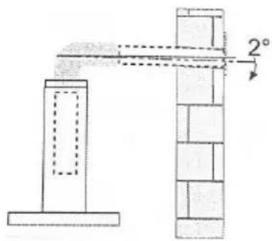
natural_image
Simple line drawing of a house with a stove and fire, no text or symbols presentnatural_image
Pure technical line drawing of a mechanical bracket assembly without any text, numbers, or symbols| Option | Chimney | X Y | |
| 1 400 | X390 | 129 | 50-350 |
| 2 500 | X490 | 229 | 50-450 |
| 3 560 | X560 | 289 | 50-520 |
Accrochez la hotte
natural_image
Simple line drawing of a T-shaped structure with a vertical dashed line and two small dots at the base (no text or symbols)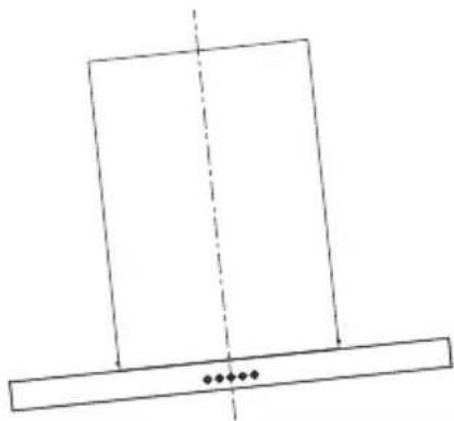
natural_image
Simple line drawing of a rectangular frame with a vertical dashed line and three small dots below (no text or symbols)Bon Mauvais
Branchements
Tuyau d'évacuation
natural_image
Illustration of a hand inserting a tablet into a device, showing a curved arrow (no text or symbols)natural_image
Technical line drawing of a mechanical assembly with a hand holding a tool (no text or symbols)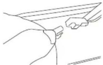
natural_image
Line drawing of a hand holding a rectangular object (no text or symbols)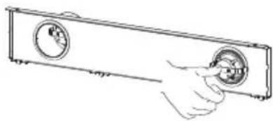
natural_image
Hand inserting a circular component into a rectangular device (no text or symbols visible)| Puissance Max | Tension | Image | Culot | Code ILCOS D | |
| Cercle /Diamètre:70mm | 1.5 W | DC 12V | 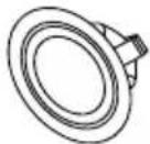 | -- | DSR-1.5-S-70 |


- orima
- MANUAL DE INSTRUÇÕES
- MODO DE UTILIZAÇÃO
- Fixador C
- Correto Incorreto
- LIGAÇÕES
- UTILIZAÇÃO
- Exaustor
- SERVIÇO DE APOIO AO CLIENTE
- INSTALLATION
- USE
- MAINTENANCE
- As a first step, proceed with the following drawings:
- Mark Points:
- Fix the brackets :
- Lower decorative chimney
- Hook the hood body
- Right Wrong
- CONNECTIONS
- Upper Decorative Chimney
- GREASE FILTERS
- ACTIVATED CHARCOAL FILTER (RECIRCULATION VERSION)
- REPLACING THE ACTIVATED CHARCOAL FILTER
- LIGHTING
- Dismantle LED light module
- Reinstall LED light module
- DISPOSAL OF OLD ELECTRICAL APPLIANCES
- SISTEMA DE ESCAPE DE AIRE POR CONDUCTOS
- Ajuste de velocidad
- Accrochez la hotte
- Bon Mauvais
- Branchements
- Tuyau d'évacuation
Brand : Orima
Model : ORC60630T
Category : Range hood