— Motorcycle — Mode d'emploi PDF")
SE4.5iF (2010) - Motorcycle Sherco - Free user manual and instructions
Find the device manual for free SE4.5iF (2010) Sherco in PDF.

| Brand | Sherco |
| Model | SE4.5iF (2010) |
| Category | Off-road motorcycle (Enduro / Supermotard) |
| Overall length | 2110 mm (Enduro) / 2060 mm (Supermotard) |
| Overall width | 830 mm |
| Overall height | 1220 mm (Enduro) / 1190 mm (Supermotard) |
| Wheelbase | 1485 mm |
| Engine | Single-cylinder 4-stroke, liquid cooling, 449.4 cc |
| Valve train | 4 valves, double overhead camshafts |
| Compression ratio | 11.2:1 |
| Fuel system | Magnetti Marelli electronic injection, unleaded gasoline 95/98 |
| Transmission | 6-speed gearbox, chain, multi-disc oil-bath clutch (hydraulic control) |
| Front suspension | Paioli USD fork Ø 46 mm, travel 300 mm |
| Rear suspension | Sachs shock absorber with remote reservoir, travel 300 mm |
| Brakes | Front disc Ø 270 mm, rear disc Ø 240 mm |
| Front tires | Enduro: 90/90-21 ; Supermotard: 120/70-17 |
| Rear tires | Enduro: 140/80-18 ; Supermotard: 150/60-17 |
| Fuel tank capacity | 7.5 liters |
| Engine oil | 1.1 liter, SAE 10W40 |
| Battery | 12V 7Ah |
| Lighting | Headlight 12V 35/35W, position light 12V 5W, rear/stop light 12V 21/5W, turn signals 12V 10W |
| Starting | Electric starter |
| Instrumentation | Multifunction digital display (speed, odometer, trips, chronometer, tachometer, etc.) |
| Weight | Not specified in the manual (approx. 120 kg) |
Frequently Asked Questions - SE4.5iF (2010) Sherco
User questions about SE4.5iF (2010) Sherco
0 question about this device. Answer the ones you know or ask your own.
Ask a new question about this device
Download the instructions for your Motorcycle in PDF format for free! Find your manual SE4.5iF (2010) - Sherco and take your electronic device back in hand. On this page are published all the documents necessary for the use of your device. SE4.5iF (2010) by Sherco.
USER MANUAL SE4.5iF (2010) Sherco
-
INTRODUCTION....P 2
-
GENERALITES
Alésage x course : 95mm x 63,4mm / 95mm x 72mm
natural_image
Close-up of a mechanical knob or dial with a numbered label (1) at the bottom, no readable text or symbols on the knob itself.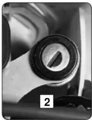
natural_image
Close-up of a mechanical knob or dial with a metallic ring and a black handle, labeled '2' in the corner (no other text or symbols visible)Contacteur à clé
natural_image
Close-up of a mechanical switch component with no visible text or symbols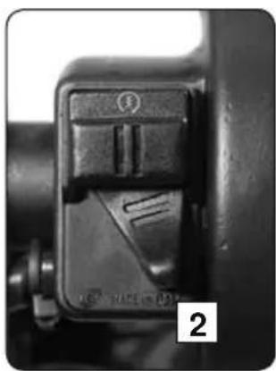
natural_image
Close-up of a mechanical switch component with no visible text or symbolsPosition 1. Courbe "soft"
Position 2. Courbe "hard"
ORGANES DE COMMANDES
natural_image
Mechanical assembly diagram showing a chain drive system with a labeled component (no readable text or symbols)Béquille latérale
natural_image
Close-up of a motorcycle's side panel and wheel, showing seat, grip, and dashboard (no visible text or symbols)Carburant
natural_image
Close-up of a hand adjusting a black mechanical component with a circular dial (no visible text or symbols)natural_image
Two gray cylindrical batteries with ribbed tops, connected by a dashed line above (no text or symbols)natural_image
Close-up of a mechanical engine component with visible brand logo and internal structure (no readable text or symbols)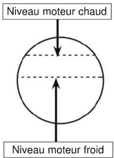
natural_image
Close-up of a camera's grip with a black circular button labeled 'MIN' and directional arrows (no readable text beyond the indicator)natural_image
Close-up of hands using a tool to adjust or install a small electronic component (no visible text or symbols)
natural_image
Close-up of a mechanical component with a 'MIN' button, no visible text or symbols beyond the labelnatural_image
Close-up of a hand adjusting a mechanical component with a black clip (no visible text or symbols)natural_image
Close-up of a motorcycle's front brake caliper with a 'MIN' button (no visible text or symbols beyond the label)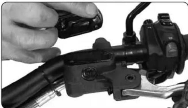
natural_image
Close-up of a hand adjusting a black brake lever handle (no visible text or symbols)natural_image
Close-up of a hand adjusting a tire pressure gauge with a car wheel and gear (no visible text or symbols)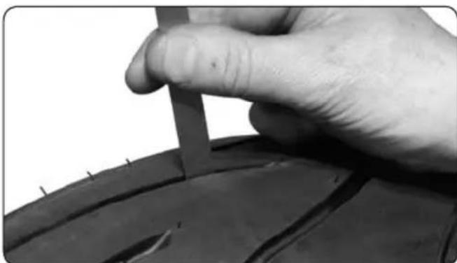
natural_image
Close-up of a hand holding a small object over a tire, no visible text or symbolsPression
natural_image
Close-up of a hand adjusting a tire wheel with a motor stator wheel (no text or symbols visible)natural_image
Close-up of mechanical components with no visible text or symbols
ATTENTION
natural_image
Close-up of a mechanical clamp or bracket component (no visible text or symbols)natural_image
Close-up of a mechanical device with lever and adjustment knob (no visible text or symbols)Position repos
natural_image
Close-up of a motorcycle's front wheel and suspension system (no visible text or symbols)Moto sur trépied.
natural_image
Close-up of a mechanical component with a white upward arrow indicating a specific feature (no text or symbols visible)natural_image
Close-up of a mechanical component with a bolted joint and internal structure (no visible text or symbols)natural_image
Close-up of a mechanical component with three circular features and a labeled section '1' (no readable text or symbols)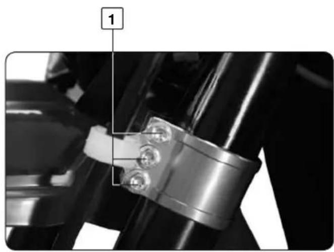
natural_image
Close-up of a mechanical component with bolts and a labeled section (no readable text or symbols)

ATTENTION
natural_image
Close-up of a hand adjusting a mechanical component with a black knob, no visible text or symbols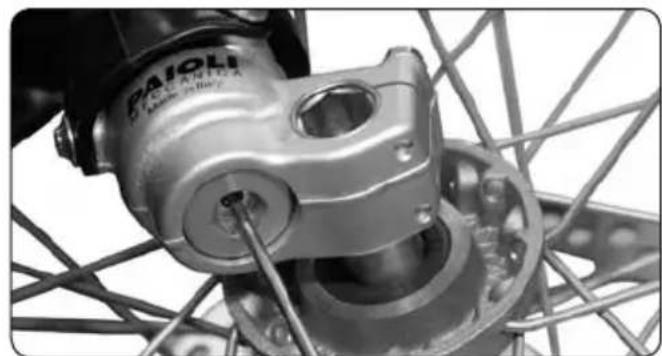
natural_image
Close-up of a bicycle wheel assembly with visible gears and hub (no text or symbols)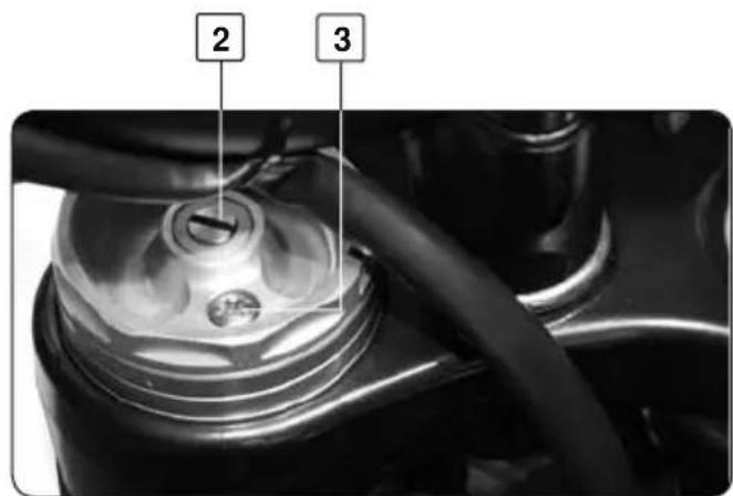
Compression de la fourche
natural_image
Mechanical assembly diagram showing a chain with bolts and a numbered component (no text or symbols present)natural_image
Line drawing of a motorcycle with gear and wheel components, no text or symbols presentnatural_image
Close-up of an automotive electrical connector with visible wiring and components (no text or symbols)natural_image
Close-up of a hand holding a small ring on a textured fabric surface, with no visible text or symbols.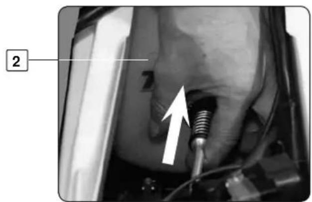
natural_image
Close-up of a mechanical component with a metallic screw and a white arrow pointing to a feature (no visible text or symbols)natural_image
Close-up of hands performing a medical or laboratory procedure on a patient's abdomen, with no visible text or symbols.natural_image
Close-up of a mechanical component with bolts and a central bolted part (no visible text or symbols)1
natural_image
Close-up of mechanical components with a hand pressing a piece, no visible text or symbols2
natural_image
Close-up of a motorcycle's internal engine components (no visible text or symbols)
natural_image
Close-up of a hand holding a tool interacting with an engine component (no visible text or symbols)Couple de serrage
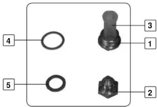
| Bouchon 1 | 22Nm |
| Bouchon 2 | 22Nm |
| Bouchon 6 | 15Nm |

natural_image
Close-up of mechanical components with visible pipes and a numbered label (3), no readable text or symbols present.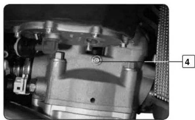
natural_image
Close-up mechanical assembly showing internal components and a numbered label (4), no readable text or symbols present.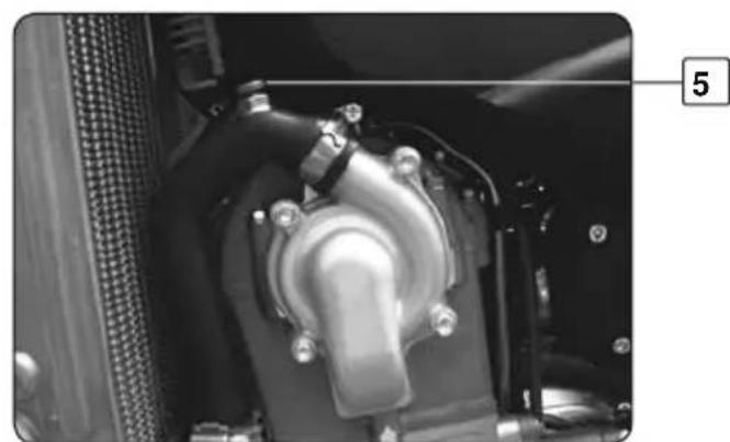
natural_image
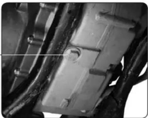
Close-up of a mechanical component with metallic parts and bolts, no visible text or symbolsVidange

ATTENTION
natural_image
Black YUASA motorcycle battery with visible model number Y178-BS and branding (no text beyond model markings)REPLACEMENT D'UNE AMPOULE DE PHARE
natural_image
Close-up of a hand adjusting a mechanical component with visible wiring and mounting brackets (no text or symbols)natural_image
Close-up of a black hat with attached wires and a numbered label (1) pointing to it, against a blurred background (no readable text or symbols)
ATTENTION
natural_image
Close-up of a mechanical assembly with labeled component '3' (no readable text or symbols beyond label)natural_image
Close-up of bicycle wheel and gear assembly with hands adjusting components (no visible text or symbols)
ATTENTION
natural_image
Close-up of hands working on a bicycle wheel with visible spokes and gear (no text or symbols)
NOTE
Couple de serrage

natural_image
Close-up of hands assembling or adjusting a mechanical component, no visible text or symbols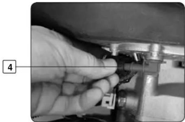
natural_image
Close-up of a hand adjusting a mechanical component with a numbered label (4) pointing to the tool area.
natural_image
Close-up of hands adjusting a mechanical component with a tool, no visible text or symbolsDépose du réservoir
natural_image
Close-up of a car's hood with a white arrow pointing to a component, no visible text or symbols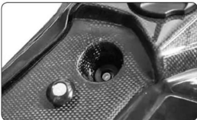
natural_image
Close-up of a mechanical component with a central hole and textured surface (no visible text or symbols)natural_image
Close-up of a metal pipe joint with a tool, no visible text or symbols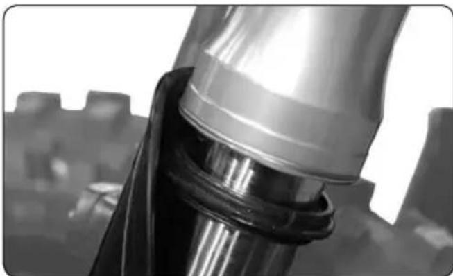
natural_image
Close-up of a metallic mechanical component with reflective surfaces, possibly a valve or connector (no visible text or symbols)natural_image
Close-up of a metallic cylindrical container with a white rectangular patch, no visible text or symbols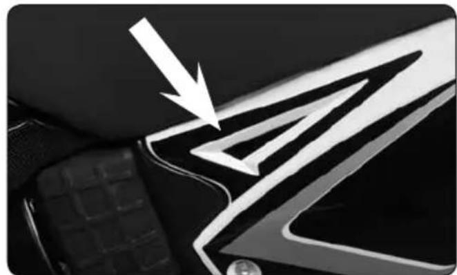
natural_image
Close-up of a car's front panel with a white arrow pointing to a stylized logo (no text or symbols visible)Thank you for the confidence you have shown in SHERCO by buying one of our products
Congratulations! You are now the owner of a 4,5i / 5,1i SHERCO Motorcycle. You will enjoy many miles or riding pleasure if you follow the instructions in this manual and obey the local vehicle codes.
This manual explains the operation, inspection, basic maintenance and upkeep of your SHERCO. Should you have any questions on the content of this manual or on your bike, please contact your SHERCO dealer.
We recommend that you read and understand everything in this manual before you ride your motorcycle.
In order to keep your SHERCO in perfect condition it is necessary that you follow the maintenance procedures described in this manual.
(The vehicle you have bought may differ slightly from the vehicle shown in this manual).
SHERCO reserves the right to make any modifications without prior notification
CONTENTS
-
INTRODUCTION....P 50
-
GENERALITIES
-
Specifications....P 52
- Véhicule description....P 54
- Location of serial numbers....P 55
- Recording the identification numbers....P 55
-
CONTROLS
-
Hands commands : clutch lever, front brake , switches....P 56
- Feet commands : gear shift lever, side stand, rear brake....P 58
-
Controls: dashboard, speedometer....P 59
-
VERIFICATIONS, LEVEL AND FILLING CHECKS
-
Fluids: fuel, cooling, engine oil, clutch and brake hydraulic fluid....P 64
- Tires ......P 68
- Spoke tension....P 69
- Front and rear brake pads....P 69
- SET UP
- Riding Position
- Handlebar, clutch lever, throttle, brake pedal....P 70
- Chain tension....P 71
- Steering bearings....P 73
- Suspensions
- Fork: compression, rebound, purge....P 74
-
Absorber: pre-load spring, compression, rebound....P 75
-
SAFETY RECOMMENDATIONS....P 77
-
RIDING
-
Start engine....P 78
- Change gear....P 78
-
Parking....P 78
-
MAINTENANCE
-
Fuses....P 79
-
Air filter.....P 80
-
Oil change / Checking oil level / replacing filter....P 82
- Emptying, filling and bleeding the cooling....P 84
- Battery....P 85
- Replacing a headlight or driving light bulb (+ removing the headlight plate).....P 86
- Removing and replacing the front wheel....P 87
- Removing and replacing the rear wheel....P 88
- Removing and replacing the fuel tank....P 89
- Cleaning the fork dust seal....P 90
-
Cleaning and storage....P 91
-
TABLES
- Maintenance....P 92
- Annual maintenance....P 93
- Recommended maintenance works by autorized sherco workshop....P 94
- Forks specifications....P 94
- Tightening torque....P 95
- Capacites (fuel tank, oil...)....P 95
- Tire pression ......P 95
SPECIFICATIONS
DIMENSIONS
Overall length : TT : 2110 mm SM : 2060 mm
Overall width : 830 mm
Height : TT : 1220 mm SM: 1190 mm
Wheelbase : 1485 mm
ENGINE
Design : Liquid cooled single cylinder 4 stro
Cooling : water
Displacement : 449,4 cm3 / 510cm3
Bore x Stroke : 95mm x 63,4mm / 95mm x 72mm
Valve timing : 4 valves, driven by tooth type chain
Ignition system : electric start
Batterie : 12V 7Ah
Electronic Injection : Magnetti Marelli
Engine oil : 1,1 litre SAE 10 W 40
TRANSMISSION
Type : 6 speed
Clutch : multi-disk in oil bath. Hydraulic command
Transmission system : chain
Primary reduction ratio : 2,72 (25/68)
Secondary reduction ratio : TT : 14/48
SPECIFICATIONS
CHASSIS
Frame : Central tube Chrome-moly-steel frame
Angle of the steering column. : 27,6°
Fork : Paioli USD ∅ 46mm
Front wheel travel : 300 mm
Rear Suspension : Sachs with separated tank, aluminium
swing arm
Rear wheel Travel : 300 mm
Front brake : disk ∅ 270mm
Rear brake : disk ∅ 240mm
Pressure TT : front and rear: 1 bar
Fuel tank capacity : 7,5 litres, Unleaded 95 and 98
ELECTRICAL EQUIPMENT
Headlight : 12 V 35/35 W
Drive light : 12 V 5 W
Rear light / stop : 12 V 21/5 W
Indicators : 12 V 10 W
TT : Enduro model
SM : Supermotard model
Specifications subject to change.
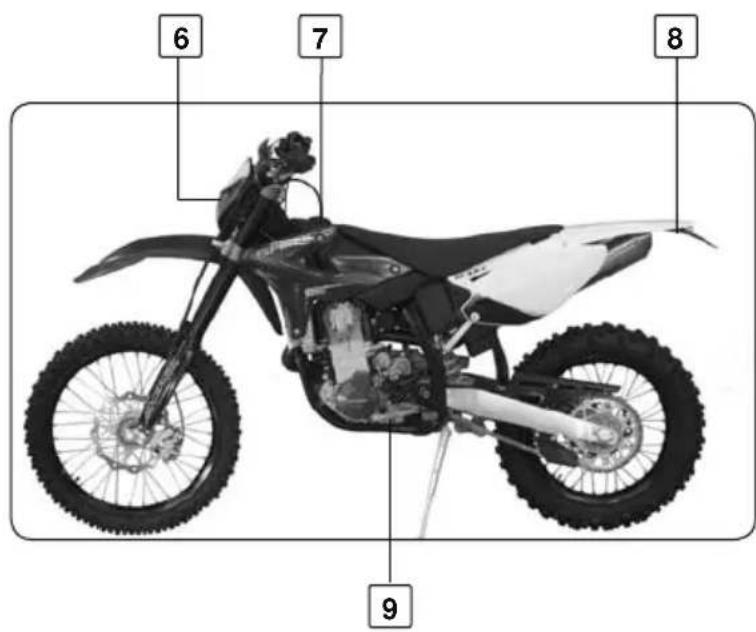
VEHICLE DESCRIPTION
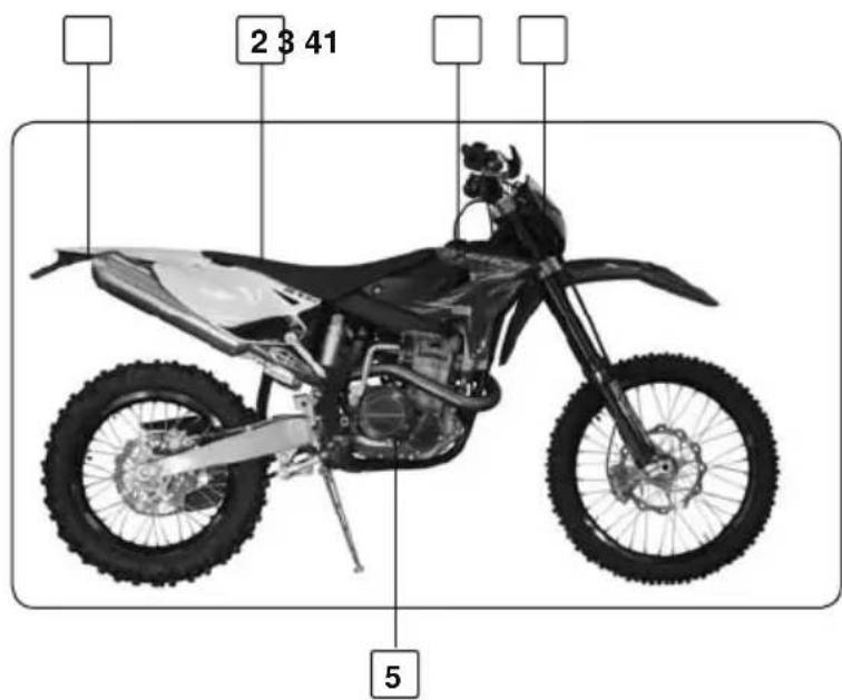
- Rear turn signal
- Seat
- Fuel tank
- Front turn signal
- Rear brake pedal
- Headlight
- Fuel tank cap
- Tail light / brake light / license plate light
-
Gear shift lever
-
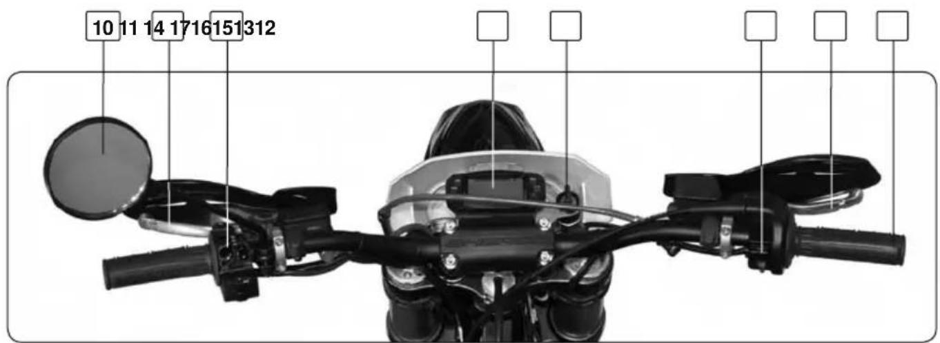
Left rear view mirror
- Clutch lever
- Left handlebar control switch
- Speedometer panel
- Main electrical switch
- Right handlebar control switch
- Front brake lever
- Accelerator grip
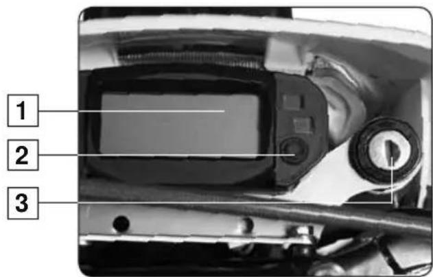
LOCATION OF SERIAL NUMBERS
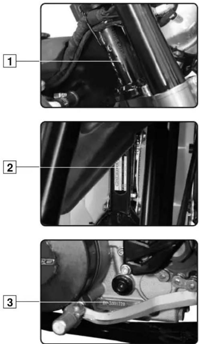
Frame number
- The vehicle serial number 1 is stamped on the right hand side of the steering column.
Identification plate
- The identification plate 2 is attached under the frame This plate indicates the emissions control number of the vehicle and the noise level in Dba at a given RPM. The identification plate also includes the machine serial number.
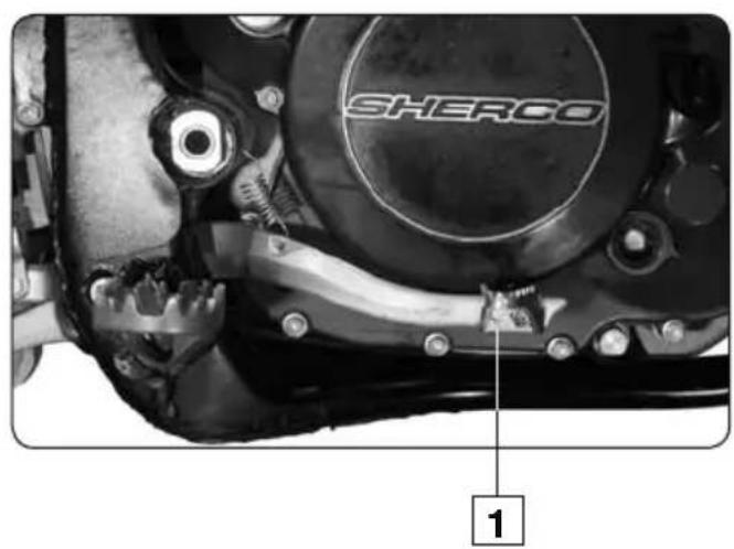
Engine type and number
- The engine 3 number is stamped on the left side or the engine.
RECORDING THE IDENTIFICATION NUMBERS
Record the numbers of the ignition key and vehicle serial numbers in the appropriate places.
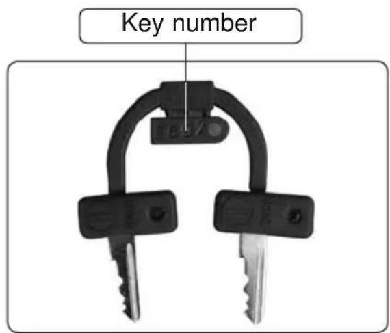
Vehicle serial number
Engine type and number
Ignition key number
CONTROLS

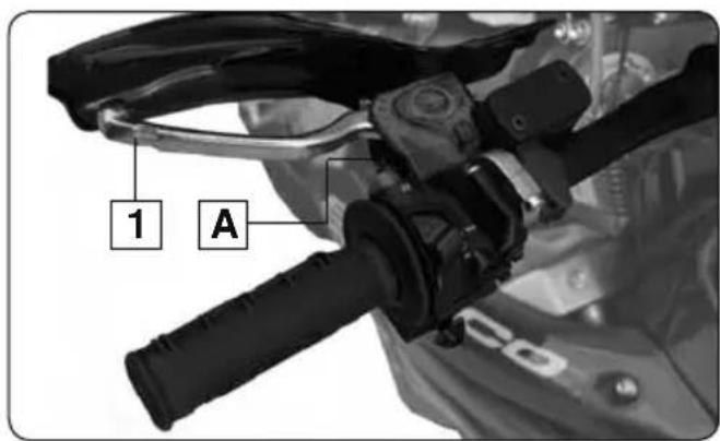
Clutch lever
The clutch lever 1 is on the left side of the handlebars and has an adjustment screw A
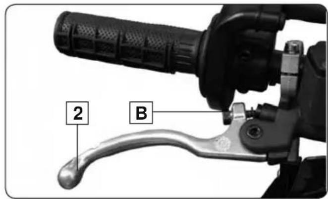
Front brake lever
The front brake lever 2 is on the right side of the handlebars and has an adjustment screw B
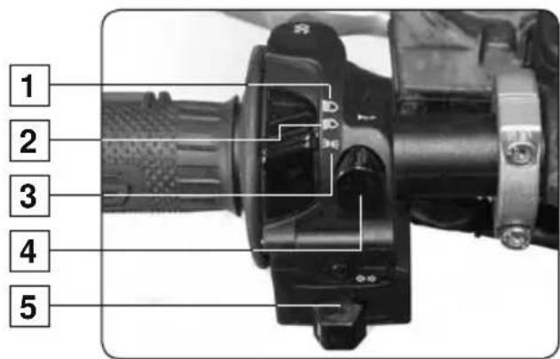
Left handlebar control switch
- Headlight (high beam)
- Headlight (low beam)
- Side lights
- Horn button
- Indicators
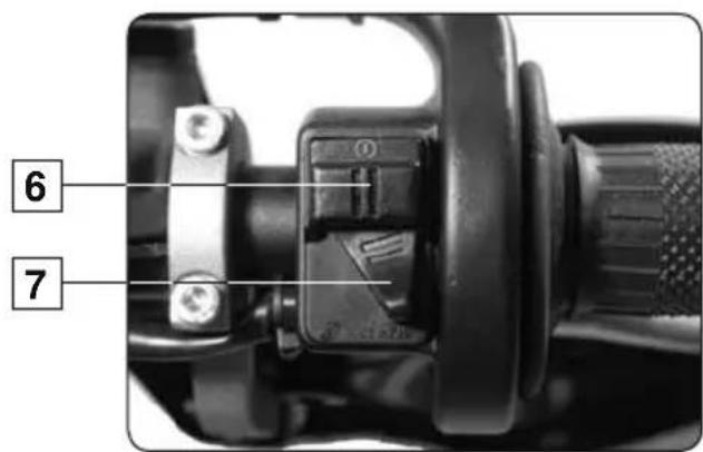
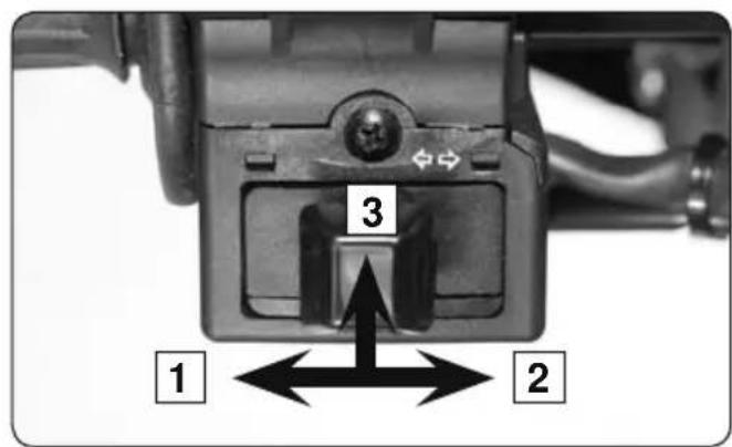
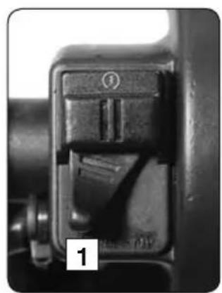
Right handlebar control switch
- Electric start button
- Twin ignition mapping switch
CONTROLS
Dashboard
- Dashboard
- Dashboard functions button
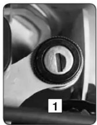
- Main electrical switch
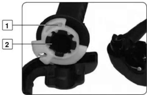
natural_image
Close-up of a mechanical knob or dial with a circular handle and central knob, no visible text or symbols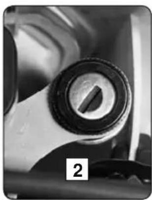
natural_image
Close-up of a mechanical component with a circular knob and a numbered label '2' (no readable text or symbols beyond the number)Main electrical switch
The switch has two positions
Position 1. The engine is off and cannot be started
Position 2. The engine can be started
Turn signal switch
- Left hand turn switch
- Right hand turn switch
- Push in to cancel
natural_image
Close-up of a mechanical component with a handle and mounting bracket (no visible text or symbols)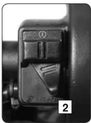
natural_image
Close-up of a mechanical switch component with no visible text or symbolsTwin ignition mapping switch
Position 1. Curve "soft"
Position 2. Curve "hard"
CONTROLS
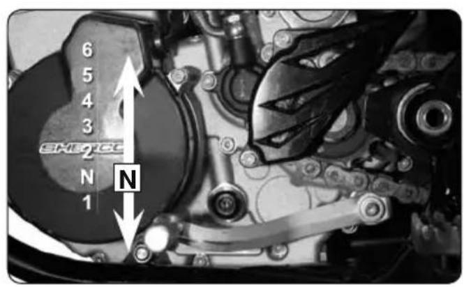
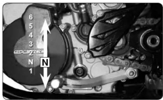
Gear shift lever
Diagram showing the six gear positions
Rear brake
- Rear brake pedal
natural_image
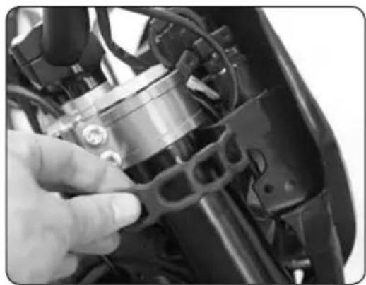
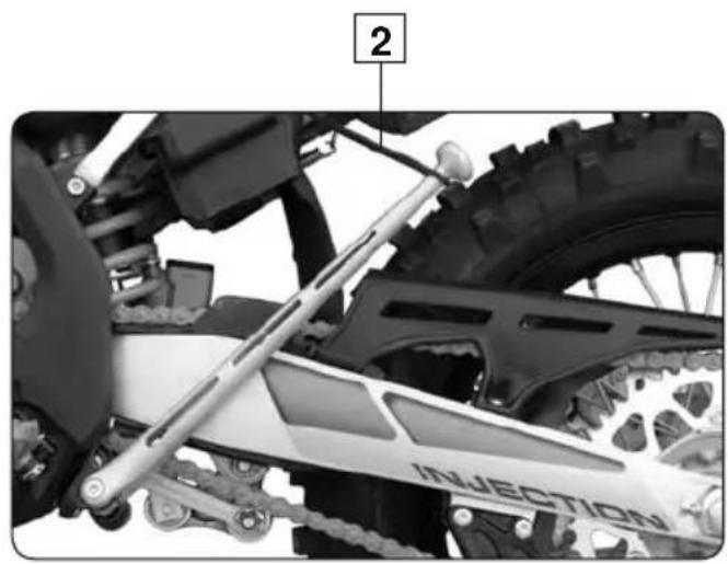
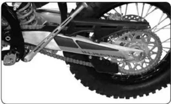
Mechanical assembly diagram showing a chain drive system with labeled component 'INJECTION' (no readable text beyond label)Side Stand
Remove the safety rubber 2, press on the stand with your foot, and keep in this position until stand supports full weight of bike.
!
WARNING
The side stand has a safety system that automatically folds it back as soon as the bike is moved into the upright position.
!
WARNING
The side stand is designed to support the motor bike alone.
DASHBOARD
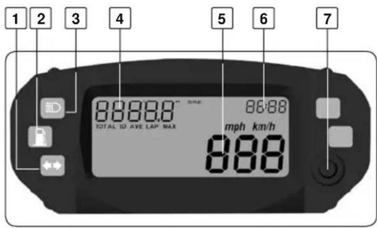
Display and lights
- Turn lights (green)
- Fuel reserve indicator (orange)
- Hight beam (blue)
- Affichage multifonctions
- Speedometer
- Time
- Speedo command
Dashboard functions
Speedometer Current speed function. (Km/h)
TOTAL Total distance function. (Km)
TD Automatic trip function. (Km)
AVE Mean speed (Km/h)
LAP Time meter
MAX Maxi speed (Km/h)
CTDWN Countdown (Km)
HPERC Operating Time (h)
RPM RPM sensor (Tr/min)

flowchart
graph LR
    A["TOTAL"] --> B["TD"]
    B --> C["AVE"]
    C --> D["LAP"]
    D --> E["MAX"]
    E --> F["CTDWN"]
    F --> G["HPERC"]
    G --> H["RPM"]
    H --> I["STDBY"]
    style A fill:#f9f,stroke:#333
    style I fill:#f9f,stroke:#333
    note right of A Button pulsations
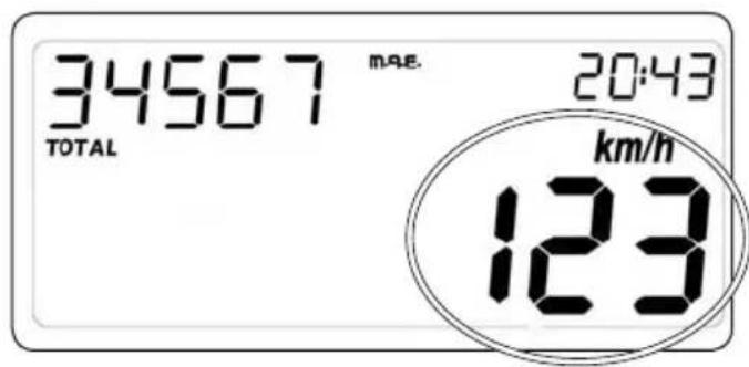
Fig1 Current speed function
Current speed function
This function describes the function/display of current speed. If the measurement unit selected is k.p.h. (default value), the relative digit is displayed; by pressing the button and gaining access to the Set-Up menu, it is possible to select m.p.h.; in this case, the speed indication will not be accompanied by any text showing the unit of measurement selected..
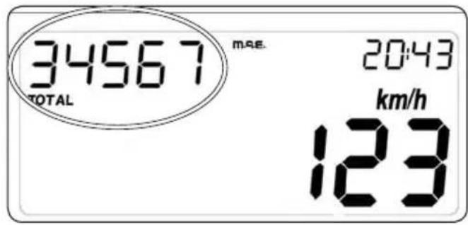
Fig2 TOTAL function
Total distance function
This function describes the function/ display of the total distance traveled. The information depending on the unit of measurement selected, the figure is shown in kilometres (default value) or miles. In normal conditions of use of the instrument, it is not possible to zero this information. The maximum figure that can be displayed is 99,999 km. (or miles); once this is exceeded, the counter is reset to zero. The figure shown increases by integer values of 1 km. /mile.
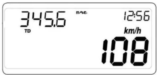
Fig3 TD function
TRIP function automatic TD
This function describes the function/display of the unit's automatic trip function; the figure shown represents the distance run by the bike expressed in kilometres or miles (depending on the unit of measurement selected), with a resolution of 0.1 (kilometres or miles); this counter is automatic: it is activated by the first impulse from the speed sensor. The figure is not saved permanently. It is possible to zero the counter associated with this parameter by pressing the button (below the TD function) for about 3 seconds until the value 000.0 appears. The zeroing of the TD can be effected both while stationary and whilst moving, and also zeroes the LAP function. If the figure exceeds 999.9, the system will automatically zero the TD and LAP, and will then restart the trip.
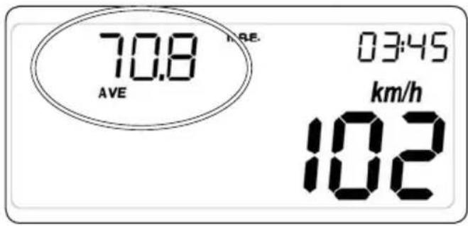
Fig4 AVE function
AVE Function Mean speed
This function determines your mean speed.
A pressure of 3 sec on the button initializes the mean speed to 0.
LAP function Automatic chronometer
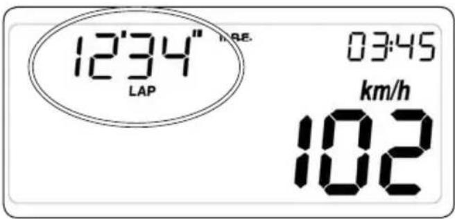
Fig5 LAP function
This function describes the function/display of the chronometer associated with theTD. The figure displays the time lapse of the bike (in mm:ss format if hours = 0, and in hh:mm format if hours > 0), associated with the TD parameter
It is therefore an automatic counter: It is automatically activated with the first impulse from the speed sensor (when LAP is operative, the digit separating hours and minutes, and minutes and seconds, flashes, and is displayed fixed when LAP is not operative), and stops 3 seconds after reception of the last impulse sent by the speed sensor. The data is not saved permanently to memory. It is possible to zero the counter associated with this parameter by pressing the button (below the LAP function) for about 3 seconds until the value 00'00" appears. The zeroing of the LAP can be effected both while stationary and whilst moving, and also zeroes the TD function. If the figure exceeds 23-59 (that is 23 h 59 min and 59 sec), the system will automatically zero the LAP and TD, and will then restart the trip function.
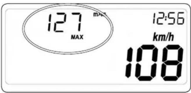
Fig6 MAX function
MAX function Maxi speed
This function shows the maximum speed of the vehicle. A pressure of 3 sec on the button initializes the mean speed to 0.
TRIP function Automatic trip Countdown
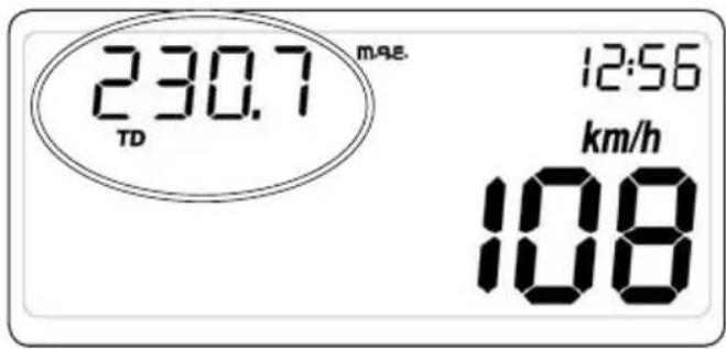
Fig7 Trip function
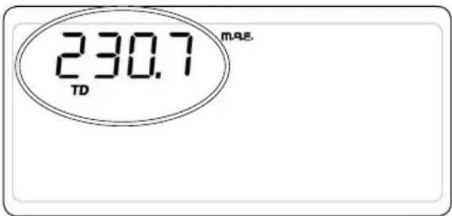
Fig8 Parameter countdown function.
This function describes the function/display of the unit's countdown trip function. The counter is always active and counts down with a resolution of 0.1 (kilometres or miles depending on the unit of measurement selected).
It is possible to modify the value associated with this parameter by pressing the button (below the TD function and whilst stationary) for about 3 seconds until only the segments relative to the countdown function and the letters TD (still flashing) are active, while all the other segments are switched off, as shown in Fig.8
It is possible to modify the different figures in the counter, starting with the largest figure and moving successively to the lesser one; depending on the data selected (shown flashing with f=1Hz, Duty=50%), a brief pressure on the button will decrease the figure by one, while a longer pressure will enable the selection of a different parameter.
Once the adjustment has been finished, normal operation mode is activated by pressing the button for about 3 seconds while the lesser figure is selected. If the figure counts down to 000.0, the system will Re-initialize the value at 999.9.
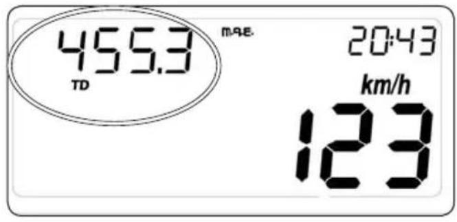
Fig9 HPERC function
HPERC function Operating Time (hours)
This function makes it possible to visualize the operating hours of the vehicle. It is not possible in normal time to modify this value or to give to zero this information. The representable largest value is 9.999 hours, exceeded such a value, the meter east gave to zero.
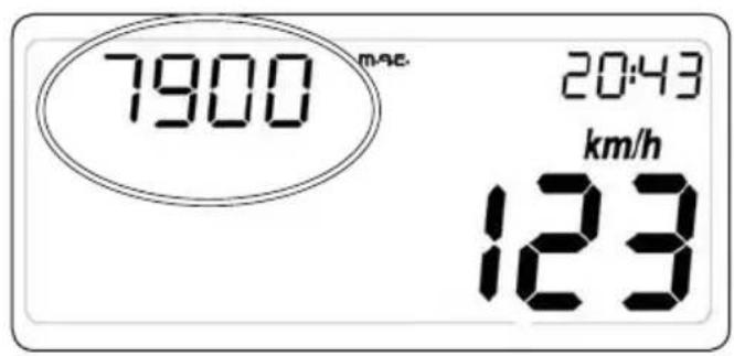
Fig10 RPM Function
RPM function RPM engine
This function makes it possible to visualize in real time, the engine speed in tr/min.
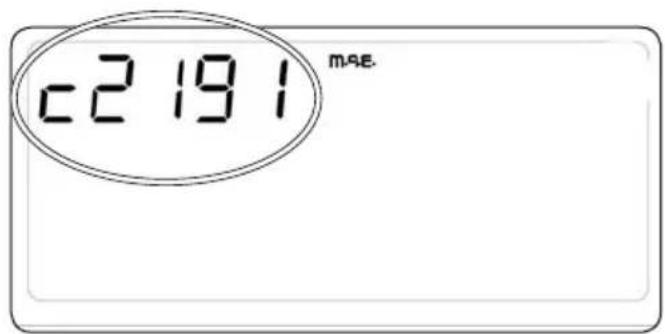
Fig11 set up adjustment of wheel circumference
| ENDURO | |
| Set up: | 2191 |
| SUPERMOTARD | |
| Set up: | 1855 |
Set up Adjustment of wheel circumference
The modification to the wheel circumference, units of measurement and number of wheel impulses can only be effected while stationary, maintaining the button pressed under the TOD function until the only information displayed is the wheel circumference and all the other segments are off (see Fig.11).
It is possible to modify the various figures constituting the value for the wheel circumference, starting with the largest figure and moving successively to the lesser one; depending on the digit selected, a brief pressure on the button will increase the figure by one, whilst a longer pressure will enable the selection of a different figure.
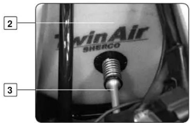
FUEL
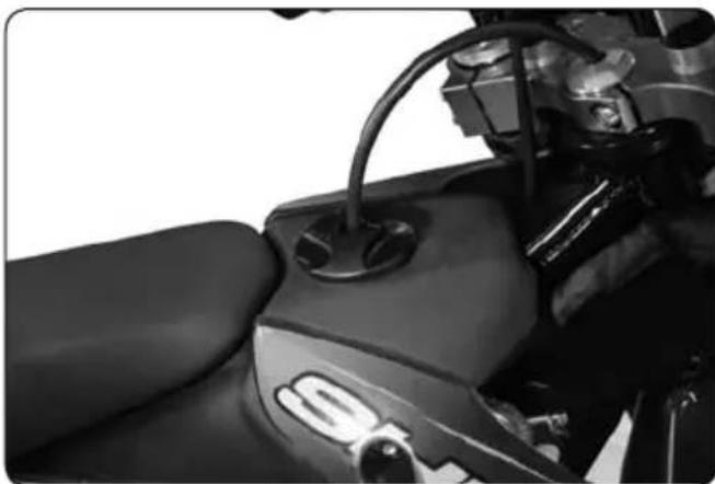
natural_image
Close-up of a motorcycle's side panel showing the wheel handle and seat (no visible text or symbols)Fuel
Only use unleaded fuel with an octane index of a least 95 or 98
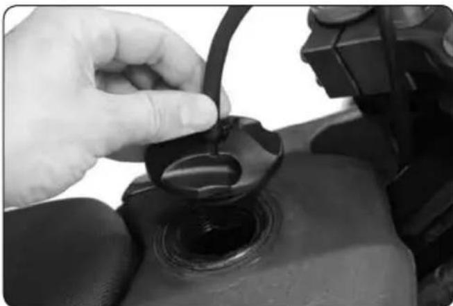
natural_image
Close-up of a hand adjusting a black mechanical component with a circular base (no visible text or symbols)Fuel tank cap
Opening: Turn the cap counterclockwise
Closing: Turn the cap clockwise

NOTE
Do not fill to the brim as fuel increases in volume as it gets hotter.
COOLING
natural_image
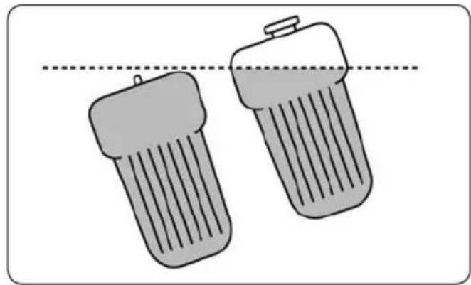
Two gray cylindrical batteries with ribbed tops, connected by a dashed line above (no text or symbols)Bike on side stand
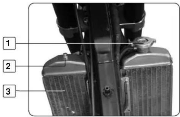
Bike is on a horizontal surface
- Radiator cap
- Radiator bleed screw
- Radiator
- Cylinder head bleed screw

WARNING
- Do not check when the engine is hot as the hot liquid can cause severe injuries.
- Cooling liquid is poisonous:
- In the event of contact with the skin or the eyes, or ingestion, or injuries caused by hot liquid:
CONSULT A DOCTOR
- Use protective gloves.
- Do not replace cooling liquid by water: It could damage your bike engine.
- Always use pre-mixed coolant
With the engine cold check the cooling fluid level and top up if necessary.
- Bike is on side stand (on left)
- unscrew bleed screws 2 and 4
- Adjust the level until liquid get out without air by the screw 4
- Replace screw 4 tight at 6Nm
- Adjust the level until liquid get out without air by the screw 2
- Replace screw 2 tight at 6Nm
- Take again the operation above for control level
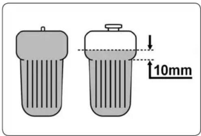
- Check that the cooling liquid level is approximately 10mm above the radiator tubes.
- Replace the cap 1 and make sure it is seated correctly
!
WARNING
It is extremely important to follow these instructions carefully. Incorrect coolant levels can cause serious damage to the engine.
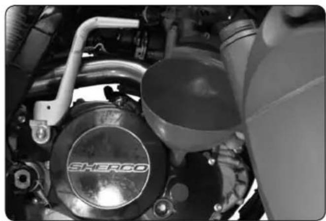
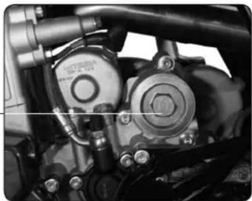
ENGINE OIL
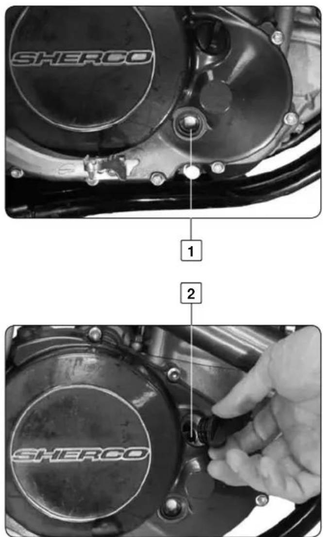
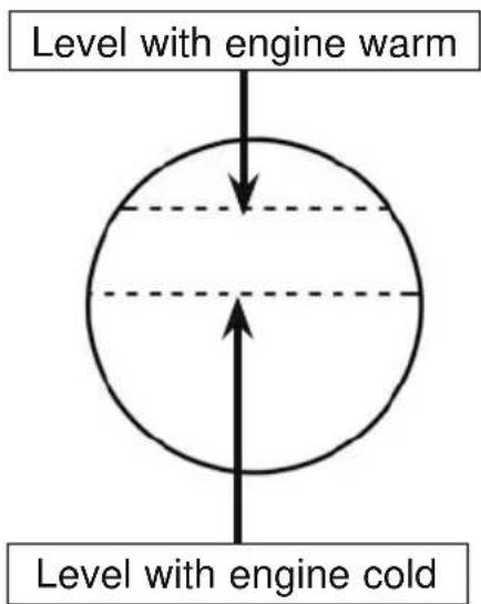
Checking oil level
- Make sure that your bike is on its two wheels, vertical and on a horizontal surface.
- Through the clutch sump window, check the level of engine oil as shown in diagram 1
Adjust the level if necessary
- Unscrew the filler cap 2 on the clutch engine oil sump,
- Top up using engine Minerva recommended by Sherco
natural_image
Close-up of a mechanical engine component with visible brand logo and internal structure (no readable text or symbols)!
WARNING
- Wrong level of oil can damage your engine
- Do not use your bike if the level is below the minimum
CHECKING THE BRAKES LEVELS
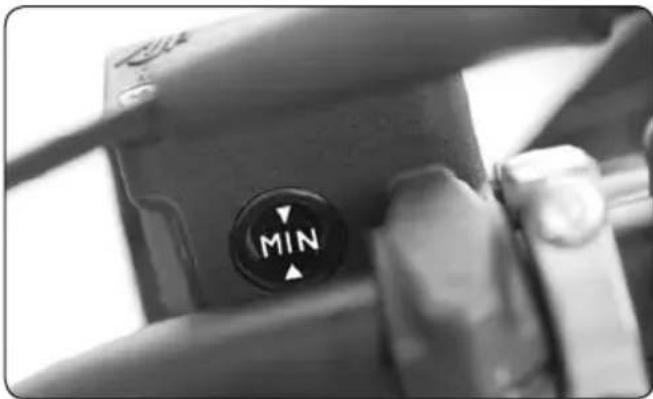
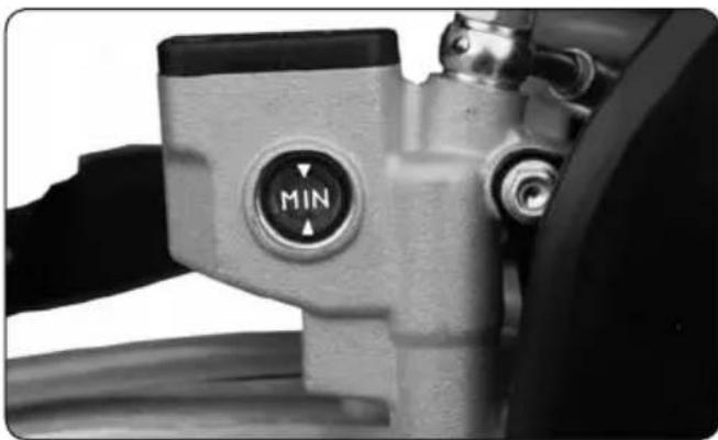
natural_image
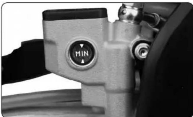
Close-up of a camera mode dial with 'MIN' button, no visible text or symbols beyond the labelChecking the front and rear brake fluid level
- With the brake reservoir in a horizontal position, the brake fluid should be able to be seen in the observation window
- The fluid should be between the two arrows as shown in the diagram below. It should be nearest to the upper arrow.
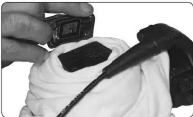
natural_image
Close-up of hands holding a small electronic device with a black connector, partially covered in white cloth (no visible text or symbols)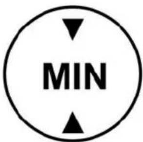
natural_image
Close-up of a mechanical component with a 'MIN' button, no visible text or symbols beyond the labelTopping up the front and rear brake fluid

WARNING
- Hydraulic fluid is highly corrosive, it can be harmful to the skin.
- Please read the recommendations on the container carefully.

natural_image
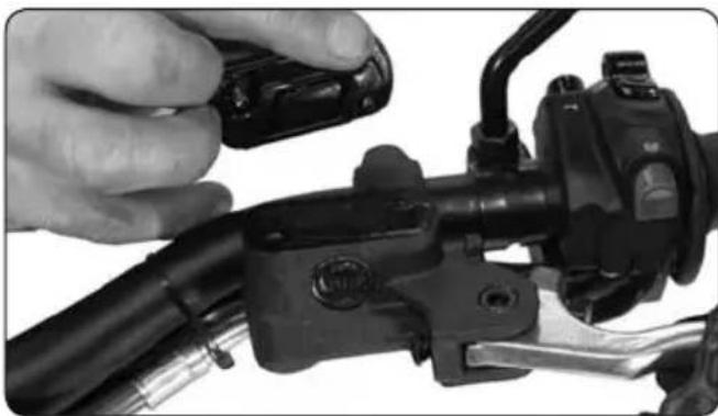
Close-up of hands adjusting a mechanical component with a black plastic clip (no visible text or symbols)- Loosen the two screws
- Remove the cap and its diaphragm.
- Fill the reservoir with DOT4 brake fluid
- Replace the diaphragm, the cap and the two screws
CHECKING CLUTCH HYDRAULIC FLUID LEVEL
natural_image
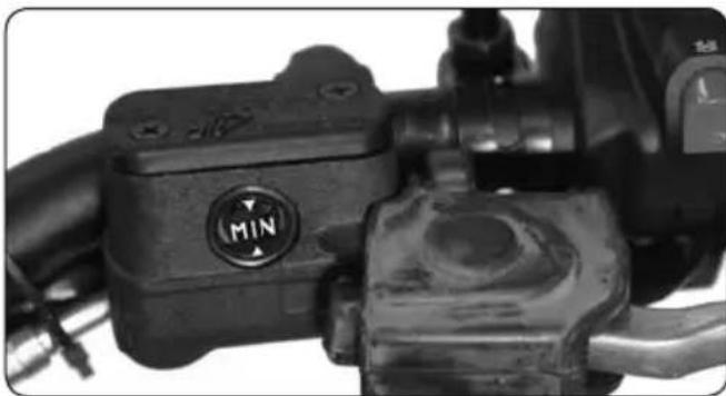
Close-up of a mechanical component with a 'MIN' button and lever mechanism (no readable text or symbols beyond the label)Checking the level
- Place the master cylinder horizontally - Check the level through window. The level should be between the two arrows Adjust the level if necessary
natural_image
Close-up of a hand adjusting a black brake caliper on a vehicle's front wheel (no visible text or symbols)Topping the clutch hydraulic fluid level
- Loosen the two screws - Remove the cap 2 and its diaphragm - Fill the reservoir with DOT4 fluid - Replace the diaphragm, the cap and the two screws

WARNING
- Hydraulic fluid is highly corrosive - It can de harmful to the skin. - Please read the recommendations on the container.
TIRES
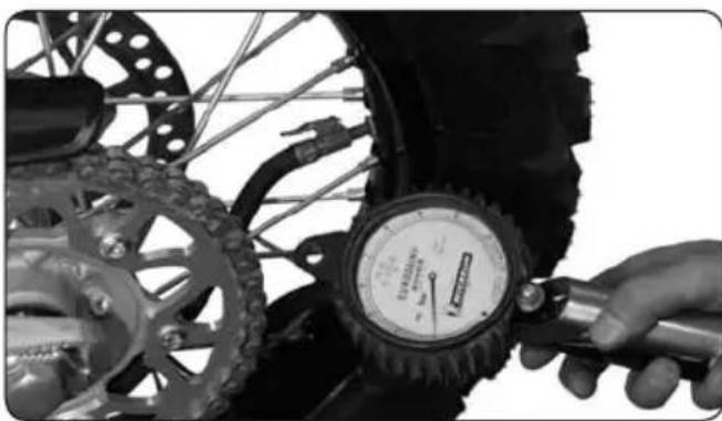
natural_image
Close-up of a hand adjusting a tire pressure gauge with a bicycle wheel (no visible text or symbols)Tire pressure
- Check the tire pressure on a regular basis with an accurate tire pressure gauge.
- The tire pressure must comply with the chart shown page 95
Tire wear and damage
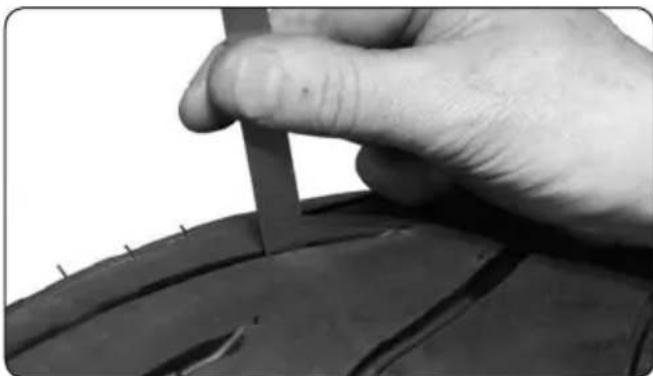
natural_image
Close-up of a hand holding a small object over a dark, curved surface (no visible text or symbols)- Check the tire pressure on a regular basis with an accurate tire pressure gauge.
- If the tread depth is less than 2 mm it is mandatory that the tire be replaced.
- Check the tires to make sure that they do not have any cuts or bulges.
- If there is a lot of damage to the tires it is mandatory that you replace them.
SPOKE TENSION
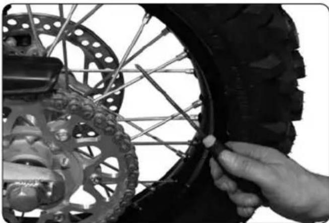
natural_image
Close-up of a hand adjusting a tire wheel rim with a motor stator wheel (no text or symbols visible)Do not forget to check the tension of the spokes

WARNING
Correct tension ensures stability and safe riding.
- Check before and after each time you use your bike, especially when it is new or if any of the spokes have been changed.
- Using a screwdriver, gently tap each spoke. The sound should ring clear
- If the sound is flat, you will need to get your spokes tensioned at a Sherco-dealership
CHECKING THE FRONT AND REAR BRAKE PADS
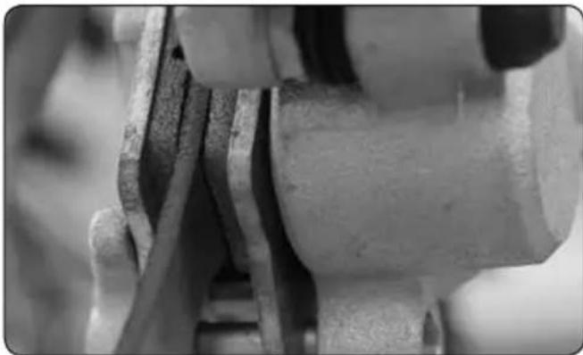
natural_image
Close-up of mechanical components with no visible text or symbols
WARNING
Checking the front and rear brake pads
Wear on brake pads should be checked regularly for the sake of your safety
Under no circumstances should it be less than one millimetre thick.
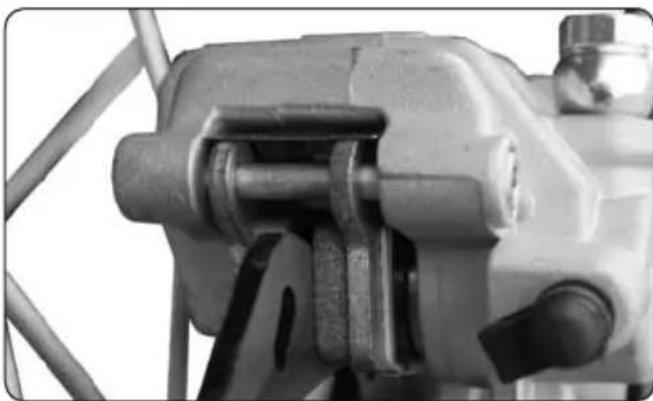
natural_image
Close-up of a mechanical clamp or bracket component (no visible text or symbols)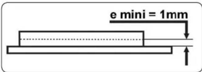
Min. thickness = 1 mm
If you should need to replace it please approach your Sherco dealer
RIDING POSITION
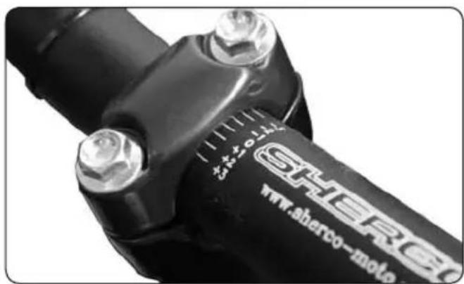
Handlebar position adjustment
- The bike comes with the handlebars in the forward position. To change to the rear position:
- Remove the handlebar
- Loosen the bottom bolts
- Turn the asymétricclamps around 180°.
- The handlebar can also be directed respect to handlebar clamps.
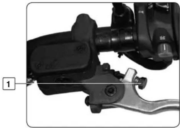
natural_image
Close-up of a mechanical device with a lever and adjustment knob, labeled with number 1 (no text or symbols on the device itself)Clutch lever adjustment
- The screw 1, allows you to adjust the position of the lever.
- If you turn it clockwise the lever moves away from the grip.
- If you turn it counter clockwise the lever moves closer to the grip.
!
WARNING
At rest the screw should have in pressure on the piston. Leave free play (movement) minimum of 1 mm
Throttle control
- The throttle control has two settings: slow action or quick action
To change the setting
- Reverse the cable position 1 on the throttle twist grip 2
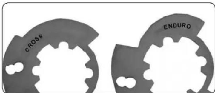
Quick action: "CROSS" side of the axis of the bike
Slow Action: "ENDURO" side of the axis of the bike
BRAKE PEDAL POSITION
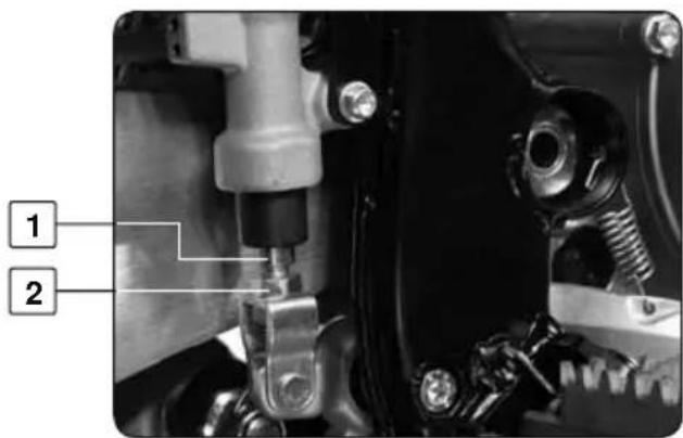
Adjusting the brake pedal position
- The free travel of the brake pedal must be 3 mm as minimum.
- Loosen the locknut 2
- Turn the stem 1 until you achieve the desired result.
- Re-tighten the locknut 2
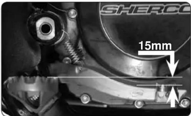
Free position
- The upper extremity of the brake pedal should be located at approximately 15 mm below the upper part of the footrest.
DRIVE CHAIN TENSION
natural_image
Close-up of a motorcycle's front wheel and suspension system (no visible text or symbols)Bike on a suitable stand
Lift the chain as shown
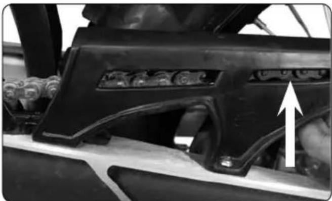
natural_image
Close-up of a mechanical component with visible gears and mounting brackets, no text or symbols presentThe position of the chain must be close to that represented on the picture.

WARNING
Poorly adjusted chain tension can lead to mechanical damage
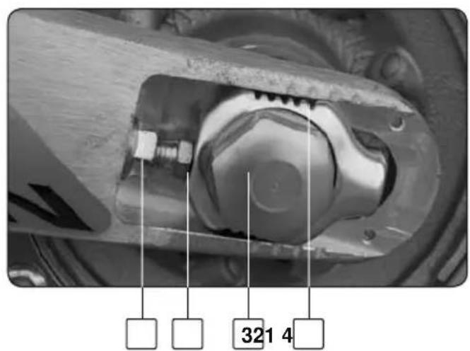
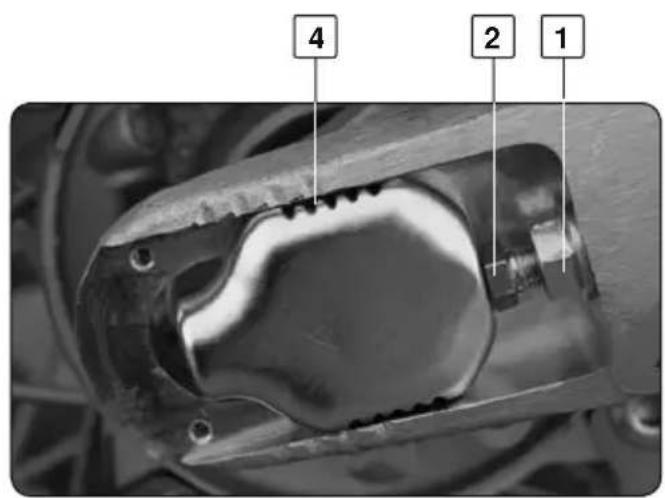
DRIVE CHAIN ADJUSTMENT
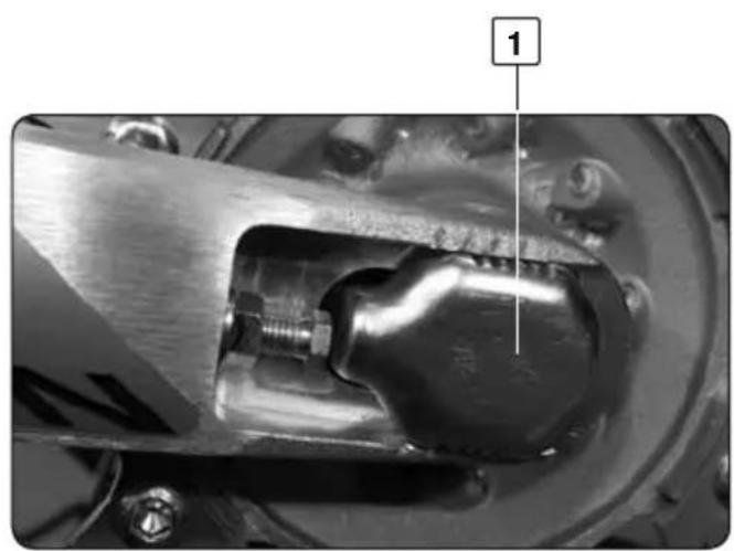
natural_image
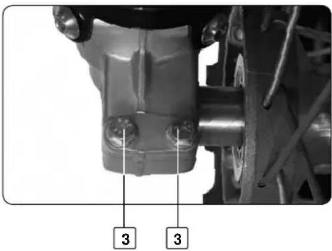
Close-up of a mechanical component with a bolted joint and metallic housing (no visible text or symbols)Chain tension adjustment
To adjust the chain tension
- Loosen bolts 3 and 1
- Loosen the screws 2 until the chain is correctly tensioned.
- Check the symmetry on either side of the arm using the marks 4.
- Tighten the bolts 1
- Tighten the bolt 3

NOTE
The sliding part is designed to adapt to the longest chains by turning it through 180°.
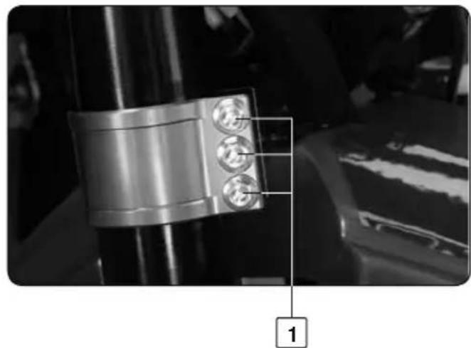
CHECKING THE FORK: TIGHTENING AND ADJUSTING THE STEERING BEARINGS
natural_image
Close-up of a metallic mechanical component with three circular features, labeled '1' in the corner (no readable text or symbols on the component itself)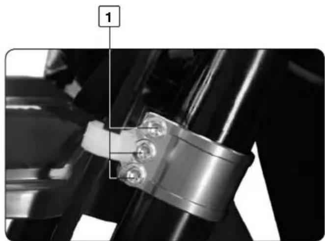
natural_image
Close-up of a mechanical assembly with three bolts and a labeled component (no text or symbols visible)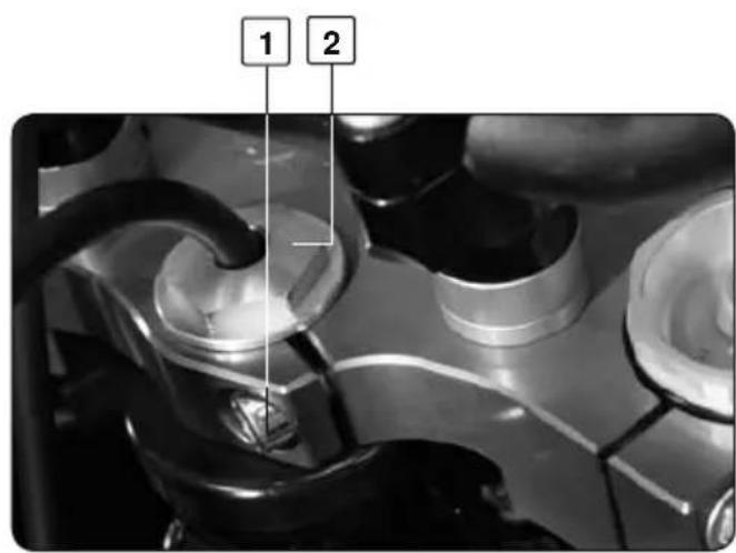

WARNING
You will need to check the steering frequently for your safety
- To do this, loosen all of the bolts marked 1.
- Tighten the steering stem nut 2 until there is no more play in the bearings. The steering should still turn freely and not bind.
- Do not tighten so much that the steering will not turn freely.
- Re-tighten all of the 1 bolts (torque 24Nm)
- Finish by tightening nut 2

NOTE
The bearings must be lubricated at least once a year with grease
FORK
natural_image
Close-up of a hand adjusting a mechanical component with a small inset detail labeled '1' (no readable text or symbols)
natural_image
Close-up of a bicycle wheel assembly with visible gears and hub (no text or symbols)

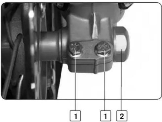
Fork compression adjustment
The screws 1 determine the behaviour of the fork when compressed. Turning them clockwise increases the compression and vice-versa.
Standard adjustment:
Turn clockwise to the stop, then back off 14 clicks
Fork rebound adjustment
The screws 2 determine the behaviour of the forks in the rebound mode.
Turning them clockwise increases the rebound and vice-versa.
Standard adjustment:
Turn clockwise to the stop, then back off 12 clicks
Fork air purge
After a period of operation, air pressure builds up in the fork.
Every 5 to 10 hours of use (depending on intensity), you will need to bleed the air.
With the forks cold, fully extend the fork, remove and then replace and tighten each screw 3 on both fork caps.
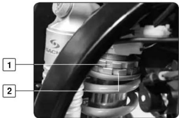
SHOCK ABSORBER
Shock absorber compression
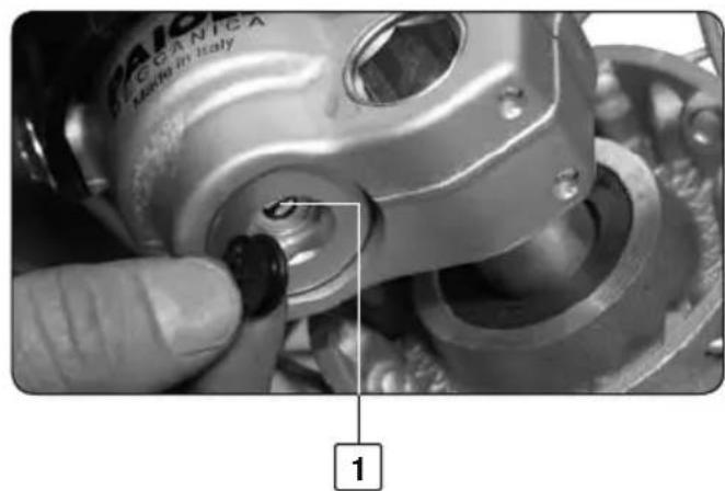
Toothed wheel 1 controls fast compression (major impacts)
Screw 2 controls slow compression (sensitivity).
turning them clockwise (+) increases the compression and vice-versa.
Standard adjustment
Toothed wheel: Turn clockwise to the stop, then back off 12 clicks
Screw : Idem
natural_image
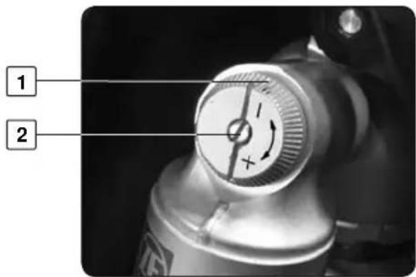
Mechanical assembly diagram showing a chain with bolts and a numbered component (no text or symbols present)Shock absorber rebound
- The rebound is adjusted by turning the black ring 3 at the base of the shock absorber There are 10 adjustment possibilities
- If you require a softer rebound, turn the black ring in the direction of the arrow marked (-).
- If you require a firmer rebound, turn the black ring in the direction of the arrow marked (+).
Standard adjustment: Turn clockwise to the stop, then back off 7 clicks
natural_image
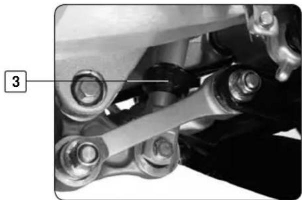
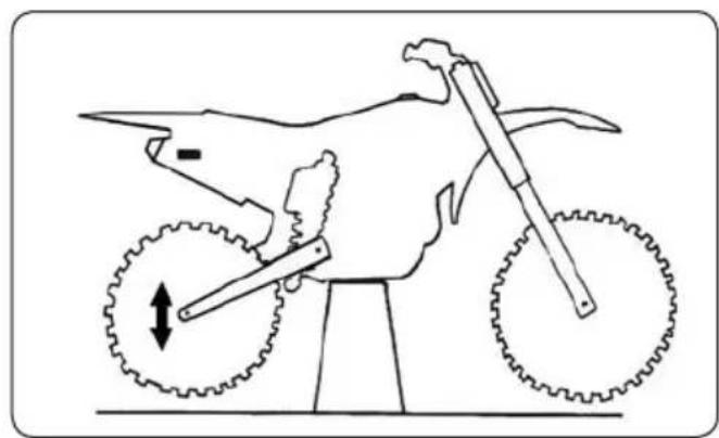
Line drawing of a motorcycle with gear and wheel components, no text or symbols presentChecking play in link rods
With the bike supported by a suitable stand, press the top and bottom of the back wheel.
If any play is found, please contact your Sherco dealer.

Pre-load adjustment of the rear shock absorber spring
To adjust the rear shock absorber spring pre-load
- Loosen bolt 1
- Turn bolt 2
- Re-tighten 1
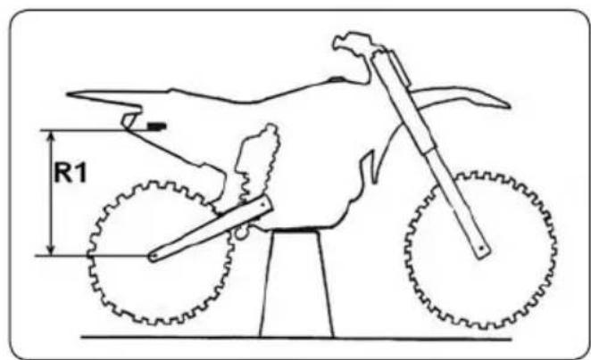
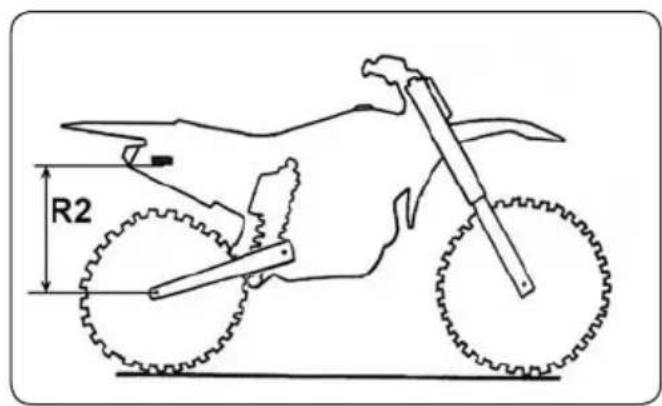
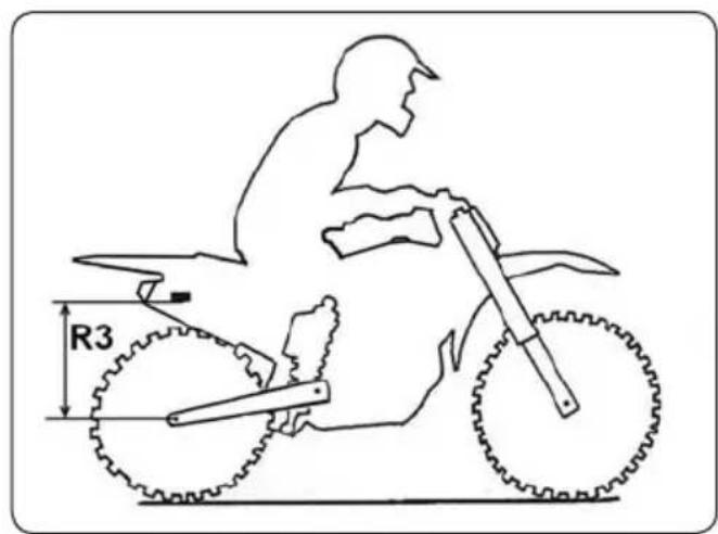
Adjust with precision pre-load of the rear shock absorber spring
- Bike supported by a suitable stand
- Measure the R1 dimension enters a fixed point of the frame and the axis of the wheels
- The bike on 2 wheels
- Measure the R2 dimension enters the same fixed point of the frame and the axis of the wheels
- Set spring preloading in order to have: R1 - R2 = 30mm
-
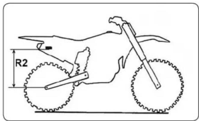
The pilot on bike
-
Measure the R2 dimension enters the same fixed point of the frame and the axis of the wheels
- Set spring preloading in order to have: R1 - R3 = 95mm

IMPORTANT
- It is preferable to respect the dimension of 30mm.
- If the dimension of 95mm is not respected, it is possible to change the stiffness of the spring to reach correct measure.
SAFETY RECOMMENDATIONS
- Never ride after drinking alcohol.
- Wear an approved helmet when riding.
- Keeping your machine in good working order and maintaining it correctly increases its reliability and safety during use.
- Petrol is inflammable, fill the fuel tank when the engine is not running.
- Exhaust fumes are toxic, never run the engine in an enclosed area.
- Always park the vehicle on a hard flat surface, do not park on a slope or soft surface. Always check that the bike is balanced.
- Before taking to the road each day, please check the following :
- Tires Wear and pressure
- Engine oil Level (page 82)
- Fuel Level + Absence of leaks
- Secondary drive chain Tightness (page 71)
- Steering Not blocked
- Brakes Operation, play, no brake fluid leaks and that the brake pads are serviceable (pages 69 and 71)
- Throttle control Play (page 70)
- Clutch Play (page 70)
- Electrical equipment Operation of horn and lights (page 86)
- Fixings (nuts, bolts, etc.) Check that all vehicle components are well secured (page 95)
If, during these checks, you find a fault, consult the Maintenance and Adjustments Chapter in this manual or contact your Sherco dealer
RIDING
Cold start
- Turn the ignition key to start position (on the right).
- Using the gear shift lever place the transmission in neutral
- Start the motor by pressing on the start button, without accelerating.
- Let the engine warm up for a few minutes.
Warm start
Follow the previous instructions but omit step 4.
- Accelerate the engine slightly after it starts
Changing gears
- The gear shift lever positions are shown page 58
-
To find neutral, push down on the pedal until it is in first gear (you will feel a resistance to further movement). Lift up slightly on the pedal.
-
Close the throttle and pull in the clutch lever.
- Step on the gear shift lever.
- Smoothly open the throttle and slowly release the clutch lever.
- Once you have reached the proper speed, shift into the next higher gear.
Parking
- Stop the engine and remove key.
Give yourself time to learn the controls and their functionsbefore using the vehicle.
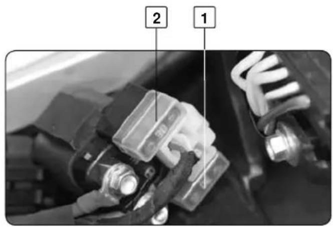
FUSES
natural_image
Close-up of an automotive electrical connector with visible wiring and components (no text or symbols)- Général fuse (30A)
- Spare fuse
- Speedometer fuse (5A)
WARNING
- Always use fuses with the right amperage
- If a fuse repeatedly blows, please consult yourSherco dealer.
Speedometer fuse
To access this fuse:
- Remove the front headlight plate. (page 86)
CLEANING THE AIR FILTER
The air filter is vital to the correct operation of your bike, so it is important to take good care of it.
A clogged air filter reduces the performance of your bike, increases fuel consumption and at the worst, dirt can enter into your engine and cause premature wear and tear.
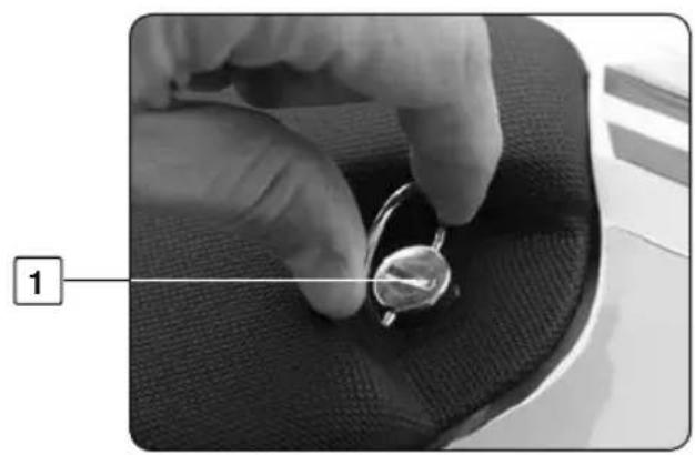
natural_image
Close-up of a hand holding a small ring on a textured fabric surface, with no visible text or symbols.Cleaning the air filter
To access the air filter :
- Loosen screw 1 on the seat by a quarter turn counter clockwise.
- Pull the seat back towards the back of the bike.
natural_image
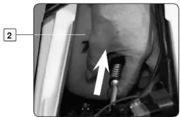
Close-up of a medical or industrial device with a metallic screw and a white arrow pointing to a component (no visible text or symbols)Press part 3 towards the filter 2 to remove part 3 from his support.
natural_image
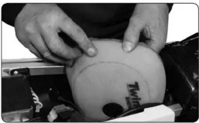
Close-up of hands performing a medical procedure on a patient's abdomen, with no visible text or symbols.- Remove the filter with its housing.
- Separate the filter from its housing.
- Clean the filter foam with a suitable detergent. (NEUTRAL)
Do not use solvent or petrol!
- Dry the filter element.
- Spray the air filter with air filter product oil until it achieves a uniform color.
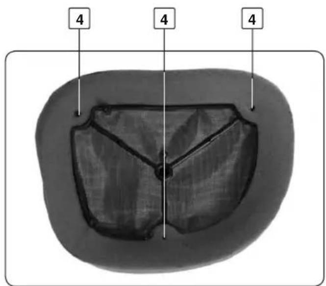
- Replace the filter element in its housing with care Make sure that the three lugs 4 are properly located
- Apply a thin film of grease to the air filter seal.
- If necessary clean the inside of the air chamber with a cloth.
- Replace the filter and its housing, taking care to centre it correctly.
- Replace the blocking part 3 (See previous page) by inserting it first into the filter assembly and then into his support.
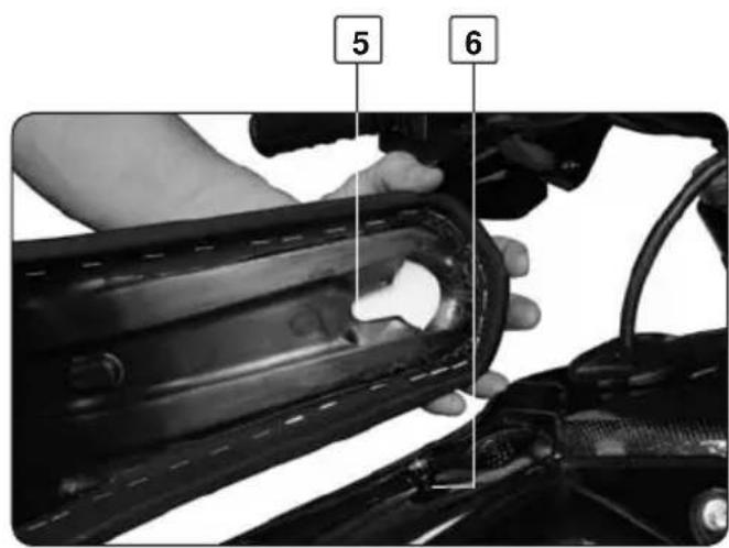
- Replace the seat forwards, making sure that the recess 5 is located in the tab 6 of the tank and the tongue is under the tank.
- Lock the screw by turning it one quarter turn clockwise.
OIL CHANGE
natural_image
Close-up of a mechanical component with visible bolts and grooves (no text or symbols)1
natural_image
Close-up of mechanical components and a damaged part, showing no visible text or symbols2
The oil should be changed when the engine is warm.

WARNING
Use protective gloves.
- Position the bike vertically on a horizontal surface.
- Place a container under the bike to catch the old oil.
- Unscrew the drain plug 1
- Unscrew the drain plug 2
- Remove the pre-filter 3
- Let the oil flow out
- Unscrew plug 6
- Remove oil filter 7 (see next page).
- Let the oil flow out
- Clean the plugs 1 and 2 with solvent
- Clean and inspect the pre-filter 3 and change it if necessary

WARNING
The plugs must 1 and 2 have new seals 4 and 5 when they are replaced.
OIL CHANGE
natural_image
Close-up of a mechanical component with visible gears and bolts (no text or symbols)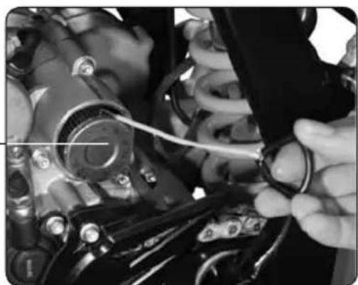
natural_image
Close-up of a hand adjusting automotive engine components with tools (no visible text or symbols)Remove oil filter
- Unscrew plug 6
- Remove the filter 7 with an hook
- Let the oil flow out
Filling engine oil
- Fit a new oil filter, in the correct direction, as shown on photo.
- Replace the cap 6 and screw to 15Nm
- Replace the plug 2 and screw to 22Nm
-
Replace the pre-filter 3 and the plug 1 as shown on photo
-
Tighten the plug 1 to 22 Nm
- Unscrew the engine oil filler cap number 2 page 66
- Pour in approx. 1,1 litre of oil recommended by the manufacturer.
- Check the level of oil through window as explained on page 66.
- Top up the level if necessary
Torque
Plug 1 22Nm
Plug 2 22Nm
Plug 6 15Nm

NOTE
The filter 7 must be replaced after every oil change.

WARNING
To protect the environment, old oil and filters should be deposited at a collection center.
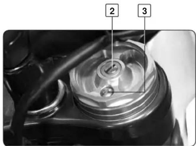
COOLING
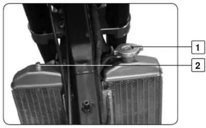
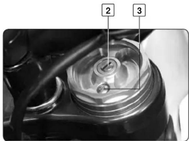
natural_image
Close-up of mechanical components with visible pipes and fittings (no text or symbols)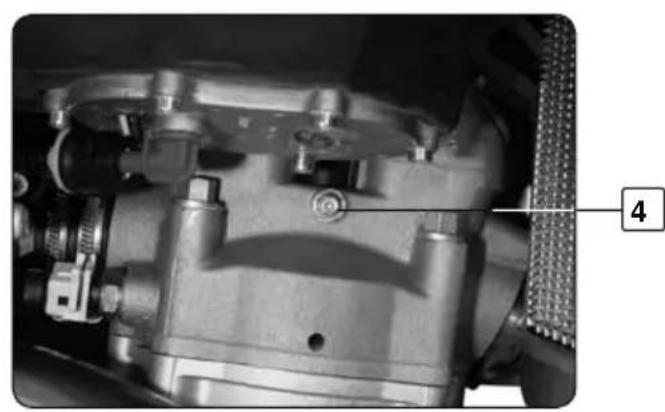
natural_image
Close-up mechanical component with no visible text or symbols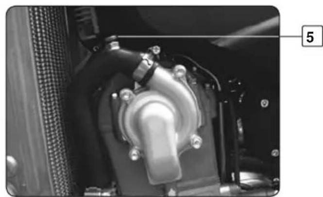
natural_image
Close-up of a mechanical component with no visible text or symbolsVidange

WARNING
Make sure that your bike is vertical and on a horizontal surface.
- Place a container under the bike
- Remove the cap 1 and the screw 3
- Let the liquid flow out
- Replace the screw 3 with a new washer
- Tighten to 8 Nm
Filling
- Loosen the bleed screw 2 on the left radiator and bleed screw 4 on the cylinder head
- Fill new new coolant through the radiator filler 1
- As soon as liquid runs through the screw 4 without bubbles then the screw 2
- Replace the screw 4 with a new washer and tighten to 6Nm
- Continue filling
- Once the level is reached (approx. 1,1 litre).
-Loosen the bleed screw 5, as soon as liquid runs, replace the screw 5. - Put the bike standing on the side stand and recover the operations described in page 65.

NOTE
To protect the environment, deposit your purged liquid at a collection center
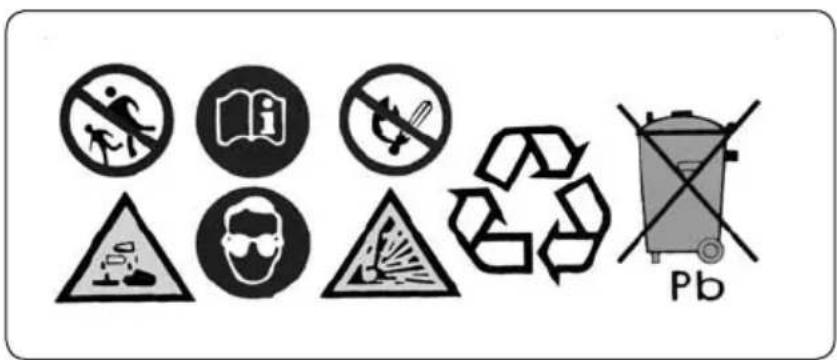
BATTERY
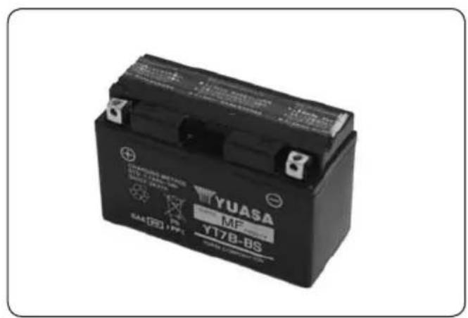
To access the battery
- Remove the seat and the air filter. See page 80
- The battery is housed at the bottom of the filter box
- Always start by disconnecting the earth terminal (-).
- Check the battery voltage when idle using a voltmeter.
- The voltage should be higher than 12,7V.
- If it is less, recharge the battery at 0,5 Ah for a maximum of 10 hours.
- Replace the battery by reversing the procedure.

WARNING
Do not cross over the terminals. This can damage the electrical circuit

NOTE
Always use the battery that is recommended by the manufacturer.
It is specifically equipped by Sherco with special protection.
REPLACING A LIGHT BULB
natural_image
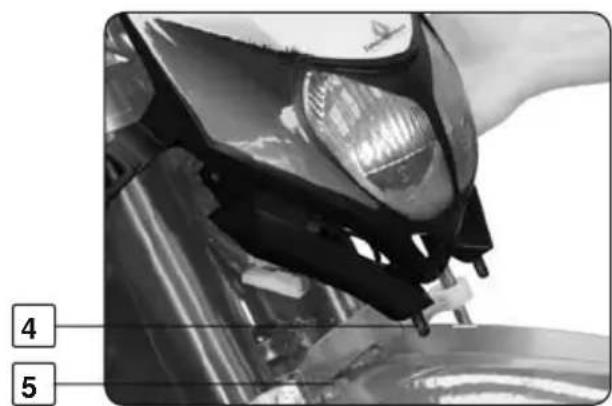
Close-up of a hand adjusting a mechanical component with visible gears and parts (no text or symbols)Removing the headlight plate
The headlight plate can be removed very quickly.
- Unclip the left and right rubbers either side of the forks
- Release the headlight plate upwards..
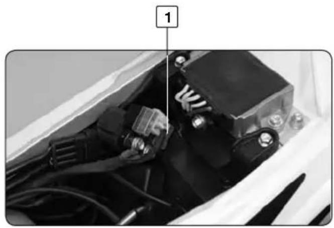
natural_image
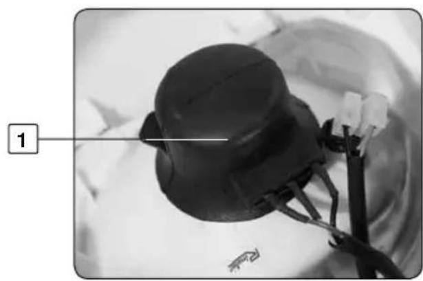
Close-up of a black hat with attached wires and a numbered label (1) pointing to it, no visible text or symbols on the object itself.Replacing a headlight or driving light bulb
- Remove the rubber protection 1
- Turn the pin 2,
- Withdraw the headlight unit.
- Press lightly on the bayonet bulb
- Turn counter clockwise to remove.
- Reverse the procedure to re-assemble.
- The driving light 3 is easily replaced by removing the bulb holder from the reflector

WARNING
Always use bulbs with the right wattage.
Reassembling the headlight plate
- Reverse the removal procedure.
- Make sure that the lugs 4 on the headlight plate are securely in the holes 5 in the front mud guard.
REMOVING AND REPLACING THE FRONT WHEEL
To remove the front wheel
- Unscrew the two screws 1 and nut 2
- Loosen the two screws 3
- Remove the axle from the right side
- Remove the wheel
To replace the front wheel
- Reverse the procedure. greasing the axle, with grease.

WARNING
Check that the screws 1 and 3 and the nut 2 are fully tightened
- Degrease the disc with solvent
- Prime the brake

NOTE
Torque
Refer to table page 95
REMOVING AND REPLACING THE REAR WHEEL
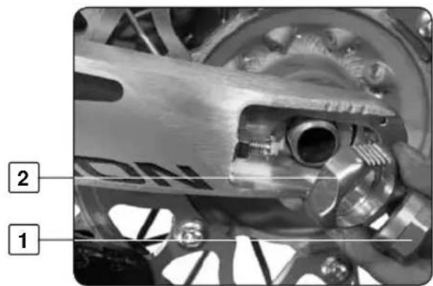
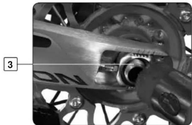
To remove the rear wheel
- Unscrew nut 1 and remove the sliding part 2
- Tap the axle 3 with a nylon mallet
- Remove it,
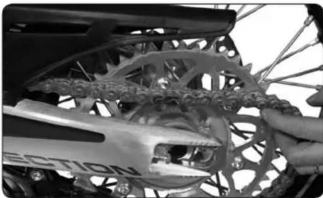
- Move the wheel as far forward as possible
- Remove the chain and the wheel.
natural_image
Close-up of a bicycle wheel assembly with visible gears and hub (no text or symbols)To replace the rear wheel
- Reverse the procedure, greasing the axle, with grease.
- Degrease the disc with solvent Brake cleaner
- Prime the brake
natural_image
Close-up of a bicycle's front wheel and suspension gear assembly, showing mechanical components and wiring (no text or symbols visible)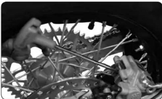
natural_image
Close-up of hands assembling a bicycle wheel with visible spokes and levers (no text or symbols)
WARNING
Check and make sure that you have properly tightened the rear axle by using it forward.

NOTE
Torque
Refer to table page 95
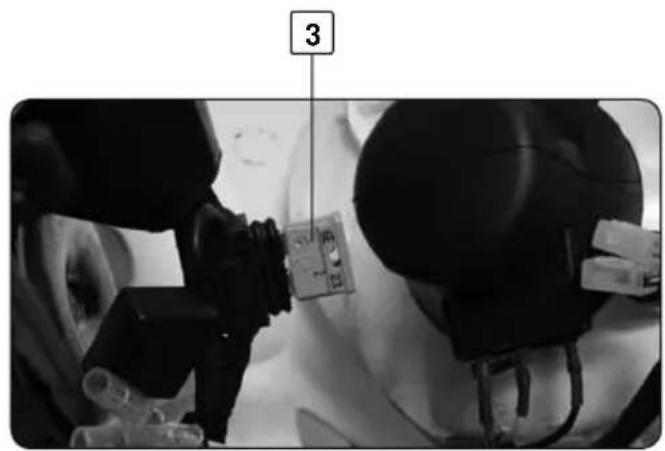
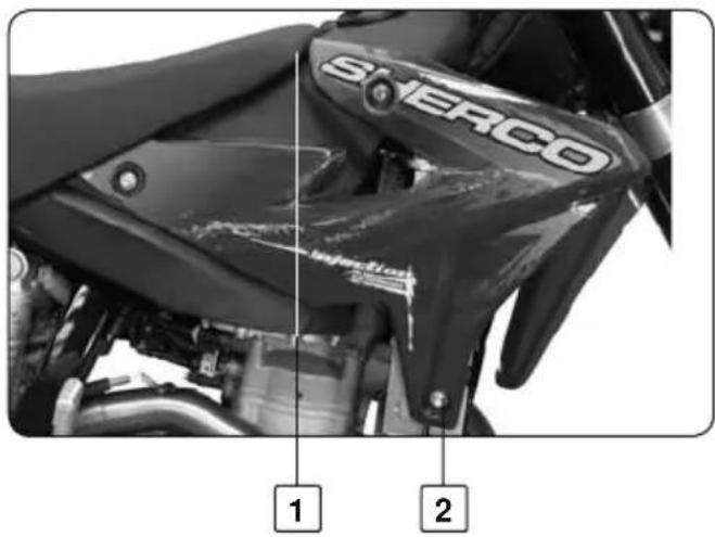
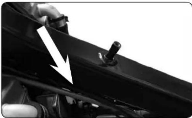
REMOVING AND REPLACING THE FUEL TANK
natural_image
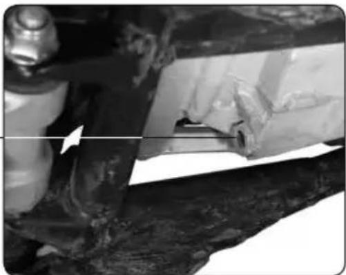
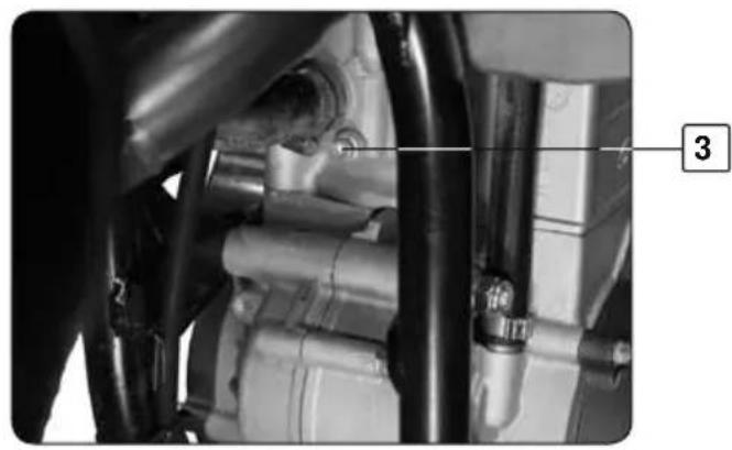
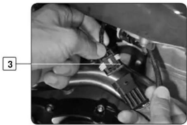
Close-up of hands installing or adjusting a mechanical component with a numbered label (3), no visible text or symbols on the main subject.
natural_image
Close-up of a hand adjusting a mechanical component with a numbered label (4) pointing to the tool area.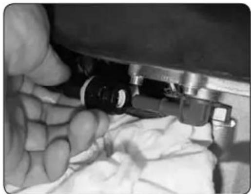
natural_image
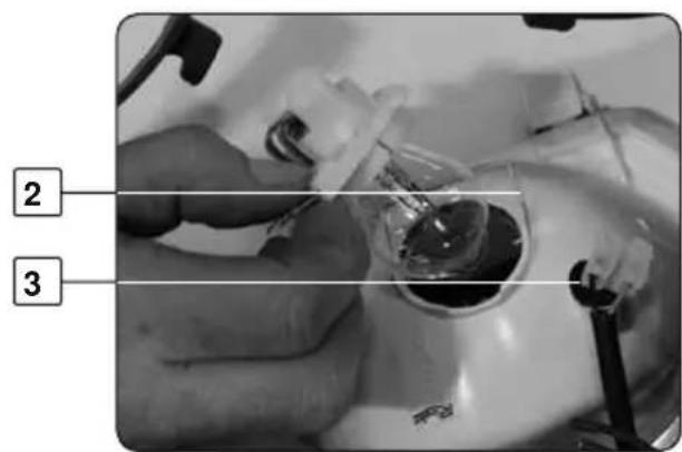
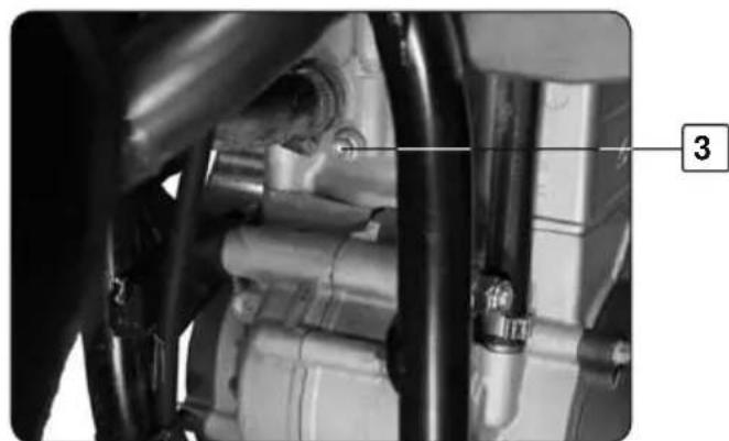
Close-up of a hand holding a mechanical component with wires and a small sensor (no visible text or symbols)To remove the fuel tank
- Unscrew the tank's central screw 1 - Unscrew the right and left lower inlet screws 2

WARNING
Wear appropriate eye protection, gloves and use a cloth
- Disconnect the fuel pump's wiring harness pin 3 - Loosen the two hose clamps securing the fuel supply hose 4. - Disconnect the fuel supply hose.

NOTE
This operation should be performed when the engine is cold
- Drain any remaining fuel into the cloth - Lift the tank upwards.

WARNING
In the event of fuel being splashed into the eyes or swallowed
CONSULT YOUR DOCTOR
natural_image
Close-up of a car hood with a white arrow pointing to a component, no visible text or symbols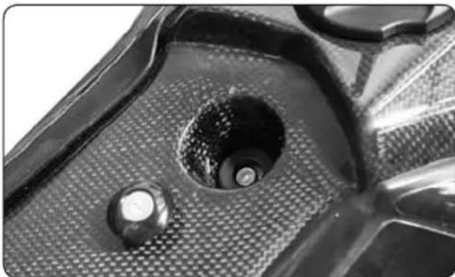
natural_image
Close-up of a mechanical component with a central hole and textured surface (no visible text or symbols)Fuel tank replacement
- Reverse the removal procedure
- Make sure that the throttle and clutch cables are correctly located, as shown in photo
- Reconnect the fuel supply line.
- Make sure you hear the connector "click" into place
- Reconnect the fuel pump's wiring harness.
- Replace the 3 screws and refit the seat
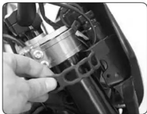
CLEANING THE FORK DUST SEAL
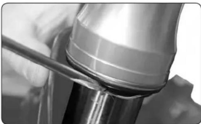
natural_image
Close-up of a mechanical component with a tool inserted, showing no visible text or symbols.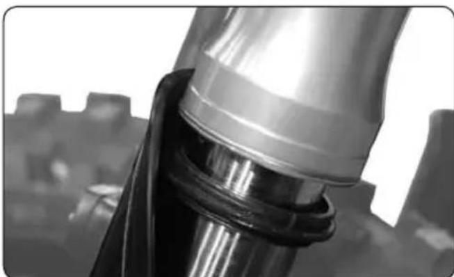
natural_image
Close-up of a metallic mechanical component with reflective surfaces, possibly a valve or connector (no visible text or symbols)Using a flat bladed screwdriver
- Carefully remove the spring
- Carefully remove the dust seal
- Clean thoroughly taking care to not damage the rubber
- Replace the dust seal
- Replace the spring
CLEANING AND STORAGE
natural_image
Close-up of a metallic cylindrical container with a white rectangular block inserted, no visible text or symbols.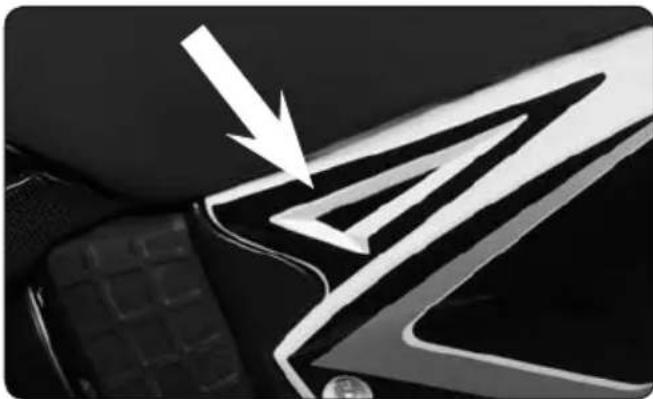
natural_image
Close-up of a car's front bumper with a white arrow pointing to the logo (no text or symbols visible)SHERCO recommends that you clean your new SHERCO 4,5i / 5,1i on a regular basis in
order to maintain its appearance and prolong its life.
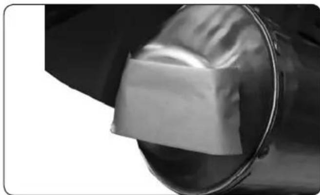
- Cover the exhaust outlet and the air filter intake with an appropriate cover. (a piece of plastic with a rubber band will work)
- To clean the engine, apply a good quality degreaser, scrub with a brush and
then rinse the engine with a water hose. - Wash the motorcycle first with a garden hose.
- Wash the rest of the vehicle with hot soapy water.
- Rinse with water.
- Dry with a chamois or a clean lint free cloth.
-
Dry the chain and lubricate it with chain lubricant.
-
Once you are finished cleaning the bike remove the covers from the intake and the exhaust. Start the engine and let it idle a few minutes.
Avoid the use of high pressure washers, the water can enter the bearings, the steering housing, etc. and cause severe damage.
Use a detergent specifically designed to wash automobiles or motorcycles, this will eliminate the possibility of damage to the tires.
Before storing the vehicle for a prolonged period (more than two months), it is recommended that you follow these instructions:
- Wash the motorcycle as described above.
- Drain the fuel tank.
-
Remove the spark plug and place some drops of engine oil in the cylinder. Turn the engine doing several impulsions with electric starter, this will cover the internal sur faces of the cylinder with oil. Replace the spark plug.
-
Lubricate all of the pivot points and cables.
-
Lift the motorcycle in order that the wheels leave the ground.
-
Cover the exhaust exit with a piece of plastic to keep moisture from entering the engine.
-
Place a thin coating of engine oil on all non painted metallic surfaces.
-
Cover the motorcycle with an appropriate cover.
| MAINTENANCE | After 5 hours | Every 20 hours |
| ENGINE | ||
| Change oil, change filter and clean prefilter ( change if necessary) | ● | ● |
| Clean drain plug magnet | ● | ● |
| Replace spark plug (After 50 hours) | ||
| Check and adjust valve clearance | ● | ● |
| Check engine mounting bolts for tightness | ● | ● |
| INJECTION | ||
| Clean venturi | ● | |
| ADD - ON PARTS | ||
| Check cooling system for leaks, check quantity of anti freeze | ● | ● |
| Check exhaust system for leaks and fitment | ● | ● |
| Check cables for damage, smooth operation and bends adjust and lubricate | ● | ● |
| Check fluid level of the clutch master cylinder | ● | ● |
| Clean air filter and filter box | ● | ● |
| Check electric wires for damage and bends | ● | |
| Check function of electric systems (low, high beam, break light, indicator lamps, speedometer illumination, emergency OFF switch or button) | ● | ● |
| BRAKE | ||
| check brake fluid, lining thickness, brake lining | ● | ● |
| Check brake lines for damage and leaks | ● | |
| Check / adjust smooth operation and free travel of handbrake / foot brake lever | ● | ● |
| Check tightness of brake system screws and leaks | ● | ● |
| CHASSIS | ||
| Check shock absorber and fork for leaks and function | ● | ● |
| Clean dust bellows | ● | |
| Bell fork legs | ● | |
| Check tightness of general bolt and screw | ● | |
| Check / adjust steering head bearings | ● | ● |
| WHEELS, SPOKE | ||
| Check joint tension and rim join | ● | |
| Check tyres and air pressure | ● | ● |
| Check chain, rear sprockets and chain guides for wear, fit and tension | ● | ● |
| Lubricate chain | ● | ● |
| Check clearance of wheel bearings | ● | ● |
| MAINTENANCE | ||
| IMPORTANT THE FOLLOWING CHECKS SOULD BE CARRIED OUT ONCE A YEAR ! | At least once a year | |
| Fork | ● | |
| Absorber | ● | |
| Clean and grease steering head bearings and gasket elements | ● | |
| Replace glass fibre yarn filing of the exhaust main silencer | ● | |
| Treat electric contacts and swiches with contact spray | ● | |
| Change hydraulic clutch fluid | ● | |
| Change brake fluid | ● | |
| Important checks and maintenance to be carried out by the rider | Before each start | After every cleaning |
| Check oil level | ● | |
| Check brake fluid level | ● | |
| Check brake pads for wear | ● | |
| Check lights for function | ● | |
| Check horn for function | ● | |
| Lubricate and adjust cables / gaz | ● | |
| Bleed fork legs regulary | ● | |
| Remove and clean dust bellows regulary | ● | |
| Clean and lubricate chain, cheque tension and adjust if necessary | ● | |
| Clean air filter and filter box | ● | |
| Check tyres for pressure and wear | ● | |
| Check cooling fluid level | ● | |
| Check fuel lines for leaks | ● | |
| Check all control elements for smooth operation | ● | |
| Check brake performance | ● | ● |
| Treat bare metal parts (with the exception of brake and exhaust system) | ● | |
| Treat and steering locks and light swiches with contact spray | ● | |
| Check tightness of screws, nuts and hose clamps regulary | ● | |
| WARNING | ||
| SERVICE SOULD BE DONE EVERY 20 HOURS IF MOTORCYCLE IS USED FOR COMPETITIONTHE SERVICE SHOULD BE CARRIED OUT AFTER EVERY RACE!SERVICE INTERVALLS SHOULD NEVER BE EXCEEDED BY MORE THAN 2 HOURS.MAINTENANCE WORK DONE BY SHERCO AUTHORIZED WORKSSHOPS IS NOT A SUBSTITUTE OF CARE AND CHECKS DONE BY THE RIDER! | ||
RECOMMENDED INSPECTIONS AND MAINTENANCE WORKS BY AUTORIZED SHERCO WORKSHOP
| Competition usage | Every 10h | Every 20h | Every 40h | Every 80h |
| Hobby usage | Every 20h | Every 40h | Every 80h | |
| Check the clutch disks for wear | ● | ● | ● | |
| Check the length of the clutch springs | ● | ● | ● | |
| Check the clutch drive for indentations | ● | ● | ||
| Check the outer clutch hub for indentations | ● | ● | ||
| Check the cylinder and piston for wear | ● | ● | ||
| Check the groove on the piston pin retainer for wear (visual check) | ● | ● | ||
| Check the camshaft for wear (visual check) | ● | ● | ||
| Check the spring cap for wear | ● | ● | ||
| Check the valve guides for wear | ● | ● | ||
| Replace the valves | ● | |||
| Replace the valve springs | ● | |||
| Check the function of the chain tensioner | ● | ● | ||
| Check the eccentricity of the crankshaft journal | ● | ● | ||
| Check the conrod bearings | ● | ● | ||
| Check piston pin bearing | ● | ● | ||
| Replace the crankshaft main bearings | ● | ● | ||
| Check the entire transmission including the roller and bearings for wear | ● | ● | ||
| Check the length of the bypass valve spring | ● | ● | ||
| Replace the glass-fiber yarn filling in silencer | ● | ● | ● | ● |
| Check the length chains distribution | ● | ● | ||
| Check plain camshaft bearings | ● | ● |
| FORK PAIOLI | ||
| VISCOSITY SAE-5 | ||
| ENDURO 580cm | ^3 110mm volume air | |
| SUPERMOTARD 615cm | ^3 80mm volume air | |
| STANDARD TIGHTENING TORQUES | ||
| M5 6 Nm | ||
| M6 12 Nm | ||
| M8 24 Nm | ||
| M10 40 Nm | ||
| TIGHTENING TORQUES | Loctite | |
| Magnetic drain plug 22 Nm | ||
| Drain plug with prefilter 22 Nm | ||
| Oil filter cover 15 Nm | ||
| Spark plug (with copper grease) 15 Nm | ||
| Bolt for bleeding cooling system 6 Nm | ||
| Drain bolt for cooling system 6 Nm | ||
| Rear wheel axle nut 80 Nm | ||
| Aluminium sub frame bolts 24 Nm | ● | |
| Front wheel axle nut 40 Nm | ||
| Front fork/axle bolts / axle M6 12 Nm | ||
| Brake pad bolt 8 Nm | ● | |
| Triple clamp bolts 17 Nm | ||
| Allen head screw R.P.M sensor M6 | 10 Nm | ● |

NOTE
Apply thread locker on all screws inside the engine
| TIRE PRESSURE | ||
| OFF-ROAD | FRONT | REAR |
| 1,0 bar | 1,0 bar | |
| ROAD | 1,5 bar | 2,0 bar |
| CAPACITIES | |
| FUEL TANK | 7,5 litres |
| MOTOR OIL | 1,1 litre |
SHERCO
Motorcycles
ESPAÑOL
P.97
INTRODUCCIÓN
SHERCO
natural_image
Empty rectangular frame with rounded corners (no text or symbols)ORGANOS DE MANDO
Palanca de embrague
natural_image
Close-up of a mechanical knob or dial with a numbered label (1) at the bottom, no readable text or symbols on the knob itself.
natural_image
Close-up of a mechanical knob or dial with a circular head and metallic shaft, labeled '2' in the corner (no other text or symbols visible)natural_image
Close-up of a mechanical switch or connector component (no visible text or symbols)
natural_image
Close-up of a mechanical switch component with no visible text or symbolsnatural_image
Mechanical assembly diagram showing a vehicle's suspension system with labeled component (no readable text or symbols)Caballete lateral
natural_image
Close-up of a motorcycle's side profile showing the wheel and seat (no visible text or symbols)Carburante
natural_image
Close-up of a hand adjusting a black plastic component with a circular opening (no visible text or symbols)natural_image
Two gray battery holders with ribbed tops, connected by a dashed line above (no text or symbols)Moto sobre caballete

Moto horizontal
natural_image
Close-up of a mechanical engine component with visible brand logo (SHERGO) and internal tubing (no readable text beyond branding)!
ATENCIÓN
natural_image
Close-up of a camera's grip with a black circular dial labeled 'MIN' and directional arrows (no readable text beyond the dial)
natural_image
Close-up of hands holding a small electronic device with a black connector, partially covered in white cloth (no visible text or symbols)natural_image
Close-up of a mechanical component with a 'MIN' button, no visible text or symbols beyond the label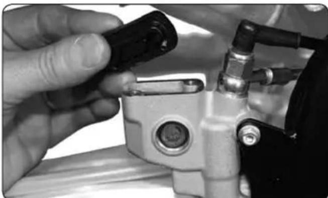
natural_image
Close-up of hands adjusting a mechanical component with a black clip and pipe fitting (no visible text or symbols)natural_image
Close-up of a black mechanical component with a circular 'MIN' button, mounted on a cable (no visible text or symbols beyond the label)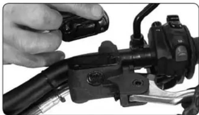
natural_image
Close-up of a hand adjusting a black brake caliper on a vehicle wheel (no visible text or symbols)natural_image
Close-up of a hand adjusting a tire pressure gauge on a motorcycle wheel (no visible text or symbols)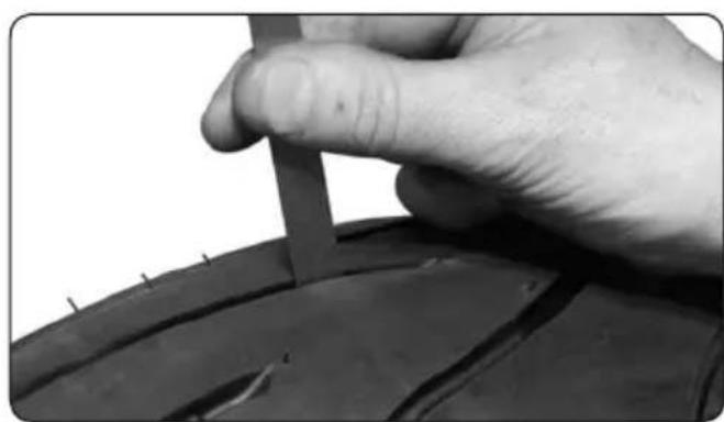
natural_image
Close-up of a hand holding a tool over a tire, no visible text or symbolsPresión
natural_image
Close-up of a hand adjusting a tire wheel next to a motor stator wheel (no text or symbols visible)natural_image
Close-up of mechanical components with no visible text or symbols
ATENCIÓN
natural_image
Close-up of a mechanical clamp or bracket component with no visible text or symbolsnatural_image
Close-up of a mechanical device with lever and adjustment knob (no visible text or symbols)Posición descanso
natural_image
Close-up of a bicycle's front wheel and suspension gear assembly (no visible text or symbols)Moto sobre un trípode
natural_image
Close-up of a black automotive chassis frame with visible mechanical components and a white upward arrow indicating motion (no text or symbols)natural_image
Close-up of a mechanical component with a metallic housing and bolted joint, labeled with number 1 (no text or symbols on the object itself)Ajustar la tensión
natural_image
Close-up of a metallic mechanical component with three circular features, labeled '1' in the corner (no readable text or symbols on the component itself)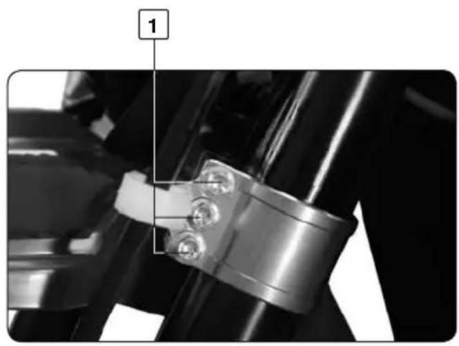
natural_image
Close-up of a mechanical assembly with a metallic bracket and bolted joint (no visible text or symbols)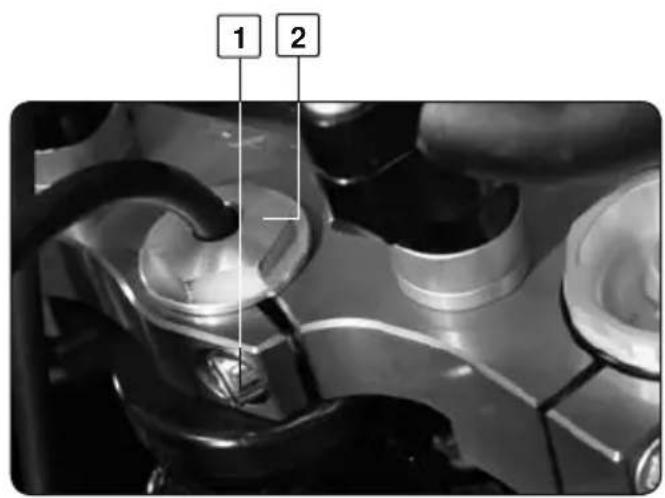

ATENCIÓN
natural_image
Close-up of a hand adjusting a mechanical component with a black knob, labeled '1' (no readable text or symbols beyond label)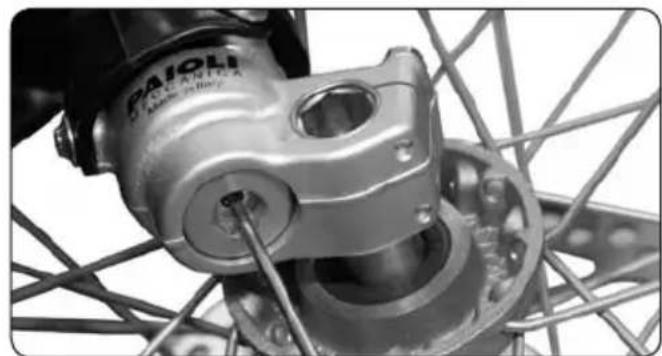
natural_image
Close-up of a bicycle wheel assembly with visible gears and hub (no text or symbols)
natural_image
Mechanical assembly diagram showing a chain with bolts and a numbered component (no text or symbols present)natural_image
Line drawing of a motor with gear wheels and a lever mechanism (no text or symbols)
natural_image
Close-up of an automotive electrical connector with visible wiring and components (no text or symbols)natural_image
Close-up of a hand holding a small ring on a textured fabric surface, with no visible text or symbols.
natural_image
Close-up of a mechanical component with a metallic screw and a white arrow pointing to a feature (no visible text or symbols)natural_image
Close-up of hands performing a ball rolling on a white surface, with no visible text or symbols.natural_image
Close-up of a mechanical component with a labeled feature '1' (no readable text or symbols beyond label)natural_image
Close-up of mechanical components with a numbered label (2) pointing to a specific part, no readable text or symbols present.natural_image
Close-up of a motorcycle's internal engine components (no visible text or symbols)6
natural_image
Close-up of hands adjusting a mechanical component with a tool (no visible text or symbols)7
natural_image
Close-up of mechanical components with visible pipes and a numbered label (3), no readable text or symbols present.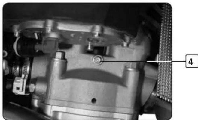
natural_image
Close-up mechanical assembly showing internal components and a numbered label (4), no readable text or symbols present.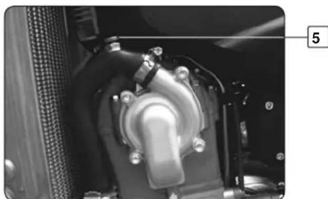
natural_image
Close-up of a mechanical component with no visible text or symbolsVaciado

ATENCIÓN
natural_image
Close-up of a hand adjusting a mechanical component with visible wiring and a circular component (no text or symbols)natural_image
Close-up of a black hat with attached wires and a numbered label (1) pointing to it, no visible text or symbols on the hat itself.ATENCIÓN
natural_image
Close-up of a mechanical assembly with visible gears and components, no text or symbols presentPara montar
natural_image
Close-up of a bicycle's front wheel and suspension gear assembly, showing mechanical components (no text or symbols visible)
natural_image
Close-up of hands assembling a bicycle wheel with visible spokes and gears (no text or symbols)
ATENCIÓN
natural_image
Close-up of hands assembling a mechanical component with a tool (no visible text or symbols)
ATENCIÓN
natural_image
Close-up of a hand adjusting a mechanical component with a numbered label (4) pointing to the tool area.
NOTA
natural_image
Close-up of a hand holding a mechanical component with wires, no visible text or symbols
ATENCIÓN
natural_image
Close-up of a car hood with a hand holding a tool, showing a white arrow pointing downward (no text or symbols visible)
natural_image
Close-up of a mechanical component with textured surface and central hole (no visible text or symbols)natural_image
Close-up of a hand using a tool to adjust or repair a metallic mechanical component (no visible text or symbols)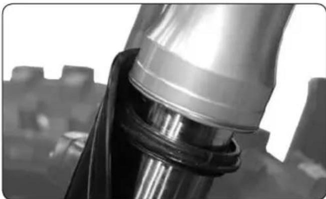
natural_image
Close-up of a metallic mechanical component with reflective surfaces, possibly a valve or fitting (no visible text or symbols)natural_image
Close-up of a metallic cylindrical container with a white rectangular patch, no visible text or symbols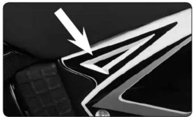
natural_image
Close-up of a car's front grille with a white arrow pointing to the grille (no text or symbols visible)More power-Less consumption.
SHERCO
PlaywithGravity
www.sherco.com