— Motorcycle — Mode d'emploi PDF")
450 SEF (2021) - Motorcycle Sherco - Free user manual and instructions
Find the device manual for free 450 SEF (2021) Sherco in PDF.

| Product type | Off-road motorcycle (enduro) |
| Brand and model | Sherco 450 SEF (2021) |
| Dimensions (L x W x H) | 2260 mm x 820 mm x (seat height 950 mm) |
| Wheelbase | 1490 mm |
| Ground clearance | 355 mm |
| Engine | Single-cylinder 4-stroke, 449.4 cm³, liquid-cooled |
| Power and torque | Not specified (manufacturer data available) |
| Fuel system | Unleaded premium (Octane 95), tank 9.7 L (including 1 L reserve) |
| Battery | Lithium 12 V 2 Ah (Factory) or Lead 12 V 4 Ah (Racing) |
| Transmission | Manual 6-speed, hydraulic multi-disc oil-bath clutch |
| Front fork | Kayaba USD ∅48 mm closed cartridge (Factory) or WP XPLOR ∅48 mm (Racing) |
| Rear shock | Kayaba with separate reservoir (Factory) or WP with separate reservoir (Racing) |
| Brakes | Front disc ∅260 mm, rear ∅220 mm |
| Tires | Front 90/90-21” or 90/100-21”, rear 140/80-18” |
| Tire pressure (off-road) | 0.9 bar front and rear |
| Lighting | Headlight S2 12 V 35/35 W, LED rear light and turn signals |
| Periodic maintenance | Engine oil and filter change every 20 hours; clean air filter after each use |
| Safety | Hydraulic brakes, kill switch, side stand with automatic retraction |
| Weight | Not specified |
| General information | Manual available for download at notice-facile.com |
Frequently Asked Questions - 450 SEF (2021) Sherco
User questions about 450 SEF (2021) Sherco
0 question about this device. Answer the ones you know or ask your own.
Ask a new question about this device
Download the instructions for your Motorcycle in PDF format for free! Find your manual 450 SEF (2021) - Sherco and take your electronic device back in hand. On this page are published all the documents necessary for the use of your device. 450 SEF (2021) by Sherco.
USER MANUAL 450 SEF (2021) Sherco
natural_image
Side profile of a white and gray off-road motorcycle with visible tracks, tires, and gear (no text or symbols)AN EMOTION IS BORN
INDEX
SHERCO
■ FRANÇAIS P.4
■ ENGLISH P.66
ESPAÑOL P. 130
DEUTSCH P. 194
INTRODUCTION
SHERCO
RÉGLAGES - FOURCHE WP SUSPENSION
Côté droit
■ Côté gauche
natural_image
Close-up of an internal mechanical assembly with gears and springs (no visible text or symbols)natural_image
Close-up of a mechanical component with two circular features, one showing internal structure and the other showing a slot (no text or symbols visible)natural_image
Close-up of a mechanical assembly with numbered components (1 and 2) and no visible text or symbolsnatural_image
Close-up of a mechanical switch or bracket component with no visible text or symbols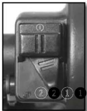
natural_image
Close-up of a mechanical component with numbered callouts (1, 2, 1) indicating specific parts, no readable text or symbols present.Position ①. Courbe "soft"
Position ②. Courbe "hard"
COMMANDE AUX PIEDS : SÉLECTEUR DE VITESSE, BÉQUILLE, FREIN ARRIÈRE
natural_image
Close-up of a mechanical component with a circular dial and numbered annotations (1 and 2) pointing to features, no readable text or symbols beyond labels.natural_image
Mechanical assembly diagram showing a worker adjusting a vehicle chassis with a ladder and labeled parts (no readable text or symbols)Fig 2 Fonction MAX
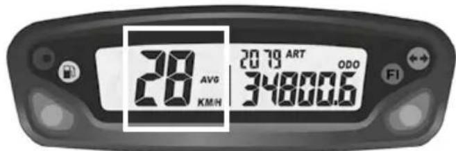
Fig 3 Fonction AVG

Fig 4 Fonction DST
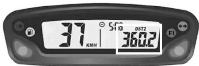
Fig 5 Fonction DST2
natural_image
Close-up of a motorcycle's front wheel and suspension components (no visible text or symbols)natural_image
Close-up of a robotic arm gripping a small object, possibly a device or tool, with no visible text or symbols.natural_image
Close-up of a mechanical component with labeled parts (1 and 2), no readable text or symbols present.
natural_image
Close-up of a hand adjusting a mechanical component, possibly a tire or bearing, with no visible text or symbols.
natural_image
Two identical cylindrical objects with vertical stripes, one emitting a droplet (no text or symbols)Moto horizontal

ATTENTION
natural_image
Close-up of a mechanical assembly with visible springs and components (no text or symbols)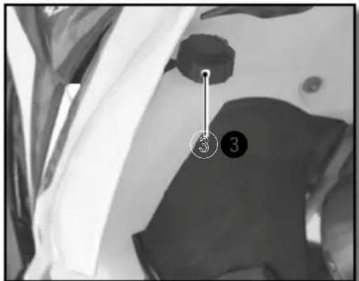
ATTENTION
natural_image
Mechanical assembly diagram showing internal components with numbered annotations (2 and 2), no readable text or symbols beyond labels.natural_image
Close-up of a bicycle brake lever mechanism with a curved arrow indicating rotational motion (no text or symbols visible)natural_image
Close-up of a motorcycle's brake lever and grip mechanism (no text or symbols visible)natural_image
Close-up of a mechanical component with a hand adjusting parts, no visible text or symbolsnatural_image
Simple hand-drawn circle with a downward arrow and two horizontal dashed lines inside, no text or symbols present.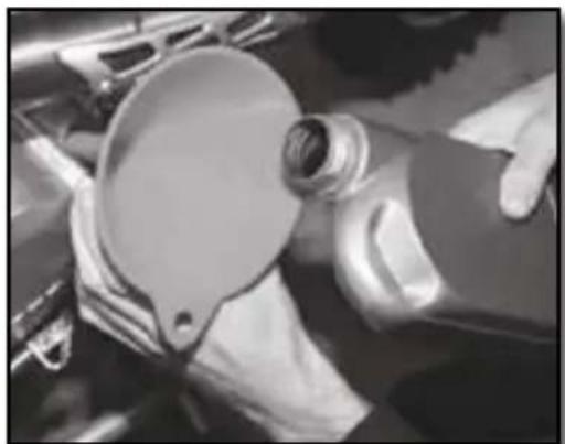
natural_image
Close-up of hands operating a mechanical component with a circular dial (no visible text or symbols)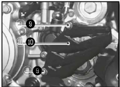
natural_image
Close-up of mechanical components including gears and springs, no visible text or symbolsnatural_image
Close-up of mechanical components with no visible text or symbolsREMLISSAGE D'HUILE MOTEUR
natural_image
Close-up of mechanical components with no visible text or symbols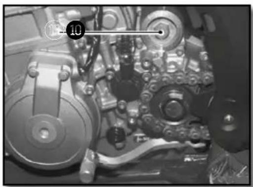
natural_image
Close-up of mechanical components with no visible text or symbols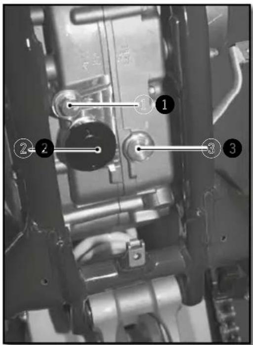
natural_image
Technical drawing of a mechanical component with cross-sectional hatching and dimension line (no text or symbols)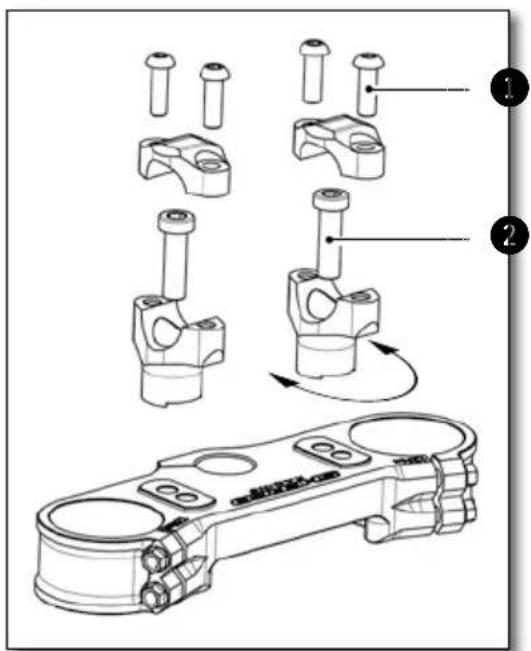
WP

natural_image
Close-up of a motorcycle's front wheel and side-mounted sensors (no visible text or symbols)KAYABA
1
| Réglage de compression WP suspension XPLOR ∅48mm (racing) | Confort 18 clics |
| Standard 15 clics | |
| Sport 12 clics | |
| Réglage de compression KAYABA (factory) | Confort 20 clics |
| Standard 12 clics | |
| Sport 8 clics | |
natural_image
Close-up of a motorcycle engine compartment with hoses and calipers (no visible text or symbols)
natural_image
Close-up of mechanical components with no visible text or symbolsnatural_image
Close-up of a mechanical wrench tool interacting with a mechanical component (no visible text or symbols)| Précontrainte du ressort WP suspension XPLOR ∅48mm (racing) | Confort 0 tour |
| Standard 0 tour | |
| Sport 2 tours |
RÉGLAGE DE LA COMPRESSION BASSE VITESSE DE L'AMORTISSEUR

WP
KAYABA
natural_image
Mechanical assembly diagram showing a shaft and valve assembly with numbered parts (1, 2, 3) in close-up viewWP
natural_image
Close-up of a motorcycle's front wheel and suspension components (no visible text or symbols)KAYABA
AMORTISSEUR WP (RACING)
natural_image
Close-up of mechanical components with no visible text or symbolsnatural_image
Close-up of a finger pressing down on a dark fabric with a key inserted, showing step 1 (no text or symbols)natural_image
Close-up of a mechanical component with visible internal blades and a numbered annotation (2) pointing to a specific part.natural_image
Top-down view of a mechanical component with multiple rods radiating from a central hub, labeled with numbers 1 and 2 (no text or symbols on the diagram itself)natural_image
Interior view of a vehicle showing a large spherical object and surrounding equipment (no visible text or symbols)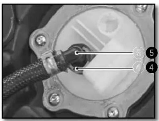
natural_image
Close-up of a mechanical component with labeled parts (no readable text or symbols)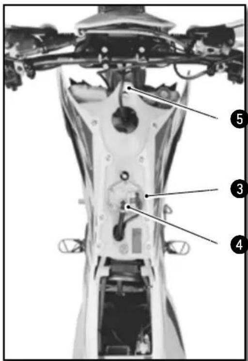
natural_image
Close-up of metallic cylindrical components with black connectors, no visible text or symbolsMoto sur trépied.
natural_image
Side view of a modified off-road motorcycle with visible dynamics arrows indicating motion (no text or symbols)Moto sur trépied.
natural_image
Close-up of mechanical components with wires and a numbered marker (no visible text or symbols)Moto sur trépied.
natural_image
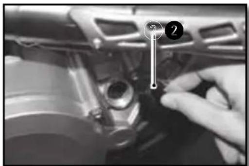
Mechanical assembly diagram showing a component with a numbered marker (7) and a vertical rod inserted into a housing (no text or symbols present)RÉGLAGE EMBRAYAGE
natural_image
Close-up of a motorcycle's steering wheel and lever mechanism (no text or symbols visible)
ATTENTION

ATTENTION
natural_image
Close-up of a mechanical assembly with numbered annotations (1 and 2) pointing to components, no readable text or symbols present.Moto sur trépied.
natural_image
Close-up of a car's engine suspension system with visible springs and hoses (no text or symbols)Entretien partie cycle (suite)
REMONTAGE DE L'AMORTISSEUR

natural_image
Black-and-white aerial view of a building with visible roof and window, marked points 3 and 4 (no text or symbols)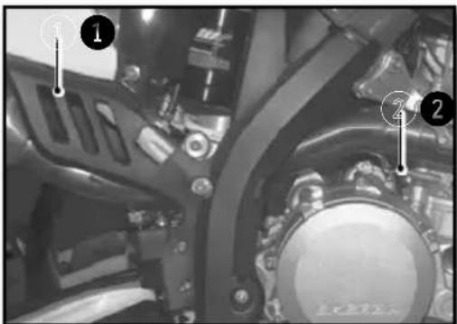
natural_image
Close-up of a bicycle wheel with visible tire tracks and mechanical components (no text or symbols)
natural_image
Close-up of a bicycle wheel assembly with mounting holes and a numbered component (no visible text or symbols)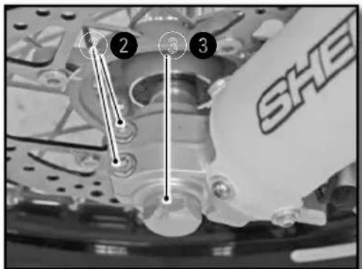
Moto sur trépied.
natural_image
Mechanical assembly diagram showing a motor and gear assembly with no visible text or symbolsnatural_image
Close-up of a bicycle wheel assembly with gear and hub (no visible text or symbols)natural_image
Close-up of a bicycle wheel with gear and hub, showing labeled components (no text or symbols beyond numbers)
natural_image
Close-up of a bicycle's wheel and gear assembly (no visible text or symbols)natural_image
Close-up of a bicycle wheel with a pressure gauge and cable, no visible text or symbolsnatural_image
Close-up of hands using a tool to adjust the wheel rim and disc (no visible text or symbols)natural_image
Mechanical assembly diagram showing a lever and shaft with labeled point A (no text or symbols beyond labels)natural_image
Close-up of a bicycle's wheel and steering wheel assembly with a numbered component (1) pointing to the handle (no text or symbols on the diagram itself)natural_image
Close-up of a mechanical assembly with hoses and connectors (no visible text or symbols)Mettre le bocal en position horizontale.

ATTENTION
natural_image
Close-up of a mechanical assembly with visible springs and bolts (no text or symbols)natural_image
Close-up of a mechanical component with a labeled section 'A' (no readable text or symbols beyond label)DÉMONTAGE DES PLAQUETTES DE FREIN AVANT ET ARRIÈRE
CONTRÔLE DES PLAQUETTES DE FREIN AVANT ET ARRIÈRE
natural_image
Pure schematic diagram of a mechanical or electrical component with no text, numbers, or symbolsCHARGE DE LA BATTERIE
natural_image
Close-up of a mechanical component with labeled parts (1 and 2), showing internal wiring and housing (no readable text or symbols)natural_image
Close-up of a connector with wires and a labeled pin (no readable text or symbols)natural_image
Close-up of mechanical components with no visible text or symbolsMettre le contact sur off.
natural_image
Close-up of mechanical components with a dial indicator and numbered annotation (no readable text or symbols)natural_image
Close-up of hands assembling a mechanical component with a tool, no visible text or symbolsAmpoule de phare S2 12V 35/35W
natural_image
Close-up of a robotic head with metallic hardware and a transparent visor, no visible text or symbolsnatural_image
Close-up of mechanical components with wires and a highlighted section (no visible text or symbols)natural_image
Close-up of a mechanical assembly with labeled components (no readable text or symbols)natural_image
Close-up of a hand holding a handheld electronic device with wires and a coin, no visible text or symbols.LAVAGE DE LA MOTO REMISAGE DE LA MOTO
We want to thank you for the trust that you have placed in us by purchasing this product.
■ You are now the owner of a SHERCO 450-500 SEF. All the pleasures of driving are promised to you if you follow the advice and instructions that SHERCO has set in this manual, and ride it in compliance with the applicable traffic laws.
This manual explains the operation, inspection, basic maintenance and focus of your SHERCO. If you have any questions about this manual or your machine, you should contact your SHERCO dealer: www.sherco.com / under «Dealers».
- Be sure to carefully read this manual in its entirety before using your machine.
To keep your SHERCO in perfect condition for many years, perform all of the care and maintenance described in the manual.
(The vehicle you purchased may differ slightly from the vehicle presented in this manual.)
■ SHERCO reserves the right to make changes without providing notice.
Serial number registration
Save the serial numbers of the vehicle in a safe location
Dealer stamp
Frame number (p.73)
Type and serial number of the motor (p.73)
SUMMARY
Technical Specifications....68
Description of the vehicle....72
Location of the serial numbers ....73
Control devices and controls....74
Hand operated controls: 74
Clutch lever, front brake lever and control switches....74
Foot controls:
gear selector, side stand, rear brake 77
Motorcycle computer instructions 78
Riding the motorcycle....82
Safety information....83
Cooling System....84
Servicing the cooling system 84
Draining the coolant....85
Filling the coolant....86
Motor settings....87
Checking the play in the throttle cable 87
Engine maintenance....88
Checking the engine oil level 88
Draining the Engine oil and removing the oil filter 89
Refilling the engine with oil....91
Adjusting the chassis....92
Handlebar position....92
Adjusting the steering angle 93
Basic setting of the chassis according to the rider weight ..93
Setting the fork compression....93
Fork rebound adjustment 94
Setting the fork spring preload....94
Adjusting the rear shock low-speed compression setting ...95
Adjusting the rear shock high-speed compression setting..96
Rebound damper 97
Setting the depression of the rear shock with no load 97
Setting the rear shock sag....97
Changing the preload of the shock 98
Changing the shock spring....98
Chassis maintenance 99
Removing the saddle....99
Reinstalling of the saddle 99
Removing the Air Filter 99
Cleaning the air filter....100
Reinstalling the air filter....100
Chassis maintenance (continued)....101
Removing the fuel tank 101
Reinstalling the fuel tank....102
Purging the air from the forks....102
Cleaning the fork dust seals 103
Checking the play of the steering head bearings....103
Adjusting the steering head bearing play....104
Cleaning the chain....104
Checking the chain tension 104
Adjusting the chain tension 105
Adjusting the lever 105
Checking the clutch fluid level....106
Removing the rear shock....107
Reinstalling the rear shock....108
Wheels, tires....109
Removing the front wheel....109
Reinstalling the front wheel 109
Removing the rear wheel....110
Reinstalling the rear wheel 110
Wheels, tires (continued)....111
Checking the tire pressure 111
Checking for wear and damage....112
Checking spoke tension 112
Brakes 113
Checking the front brake lever adjustment .....113
Adjusting the front brake lever....113
Checking the front brake fluid level....113
Filling the front brake reservoir with brake fluid .....114
Adjusting the position of the rear brake pedal....114
Checking the travel of the rear brake pedal....114
Adjusting the travel of the rear brake pedal....115
Checking the rear brake fluid level....115
Filling the rear brake reservoir with brake fluid....115
Removing the front and rear brake pads 116
Checking the condition of the brake pads....116
Reinstalling the front and rear brake pads....116
Electrical system maintenance....117
Removing the battery....117
Reinstalling the battery 118
Charging the battery 118
Replacing the main fuse....119
Replacing the fuse for the lights 119
Removing the headlight housing 119
Reinstalling the headlight housing....119
Replacing the headlight bulb or the pilot lamp....119
Adjusting the headlight beam 111
Replacing the motorcycle computer battery .....121
Washing and storage....122
Washing the bike 122
Storing the bike 122
Recommissioning after storage 122
Maintenance schedule....123
Maintenance....123
Torques....126
Technical Specifications
DIMENSIONS
| Overall length 2260 mm | |
| Overall width 820 mm | |
| Seat height 950 mm | |
| Wheelbase 1490 mm | |
| Ground clearance 355 mm |
MOTOR 450 SEF 500 SEF
| Type Single cylinder 4 stroke liquid cooled | ||
| Displacement 449,4 cc 478,22 cc | ||
| Bore / Stroke 95mm X 69,9mm 95mm X 63.9mm | ||
| Compression ratio 11.84 : 1 11.44 : 1 | ||
| Distribution | 4-valve DOHC chain drive | |
| Starting System | Electric starter | |
| Intake valve diameter | 38 mm | |
| Exhaust valve diameter | 30,5 mm | |
| Intake valve cold clearance | 0.15-0.2mm | |
| Exhaust valve cold clearance | 0.2-0.25mm | |
| Spark plug | NGK LMAR9E-J | |
| Spark plug gap | 0.7 mm | |
| Electronic injection SYNERJECT | ||
| Alternator | 12V, 220W | |
| Engine oil 1,1 litre SAE 5W40 | ||
TRANSMISSION
| Type | Manual |
| Clutch | Multi disc clutch in oil bath, hydraulically operated |
| Primary drive | 25 : 75 |
| Gearbox | 6 speed |
| Secondary drive | 14 X 49 |
| CHASSIS | |
| Frame | Semi-perimeter CrMo steel with aluminum subframe |
| Fork KAYABA closed cartridge (Factory) | |
| Rear suspension | WP Suspension Xplor (Racing) |
| Travel front/rear 300/330mm | |
| Front brake disc Disc ∅ 260mm | |
| Rear brake disc Disc ∅ 220mm | |
| Disc brakes wear limit 2.7mm avant et 3.6mm back | |
| Front tire 90/90-21” ou 90/100-21” | |
| Rear tire 140/80-18” | |
| Pressure off-road front / rear 0,9 bar | |
| Fuel tank capacity with reserve 9.7L with 1L of reserve | |
| Fuel requirement | Unleaded gasoline with an octane index of at least 95 |
| ELECTRICAL EQUIPMENT | ||
| Battery | Shido LTZS Lithium (Factory) | 12V 2Ah |
| Yuasa YTX5 LBS (Racing) | 12V 4Ah | |
| Headlight S2 12V 35/35W | ||
| Pilot W5W 12V 5W | ||
| Rear tail / stop | LED | |
| Flasher | R10W 12V 10W | |
| Speedometer battery | CR 2032 | Battery voltage: 3V |
| Plate light | W5W | 12V 5W |
Technical Specifications (continued)
ADJUSTMENTS - KAYABA FORK
| Compression | Comfort 20 clicks back | |
| Standard 12 clicks back | ||
| Sport 8 clicks back | ||
| Rebound | Comfort 18 clicks back | |
| Standard 12 clicks back | ||
| Sport 10 clicks back | ||
| Spring stiffness | Rider weight: 65-75 kg 4.2N/mm | |
| Rider weight: 75-85 kg 4.4N/mm (original) | ||
| Rider weight: 85-95 kg 4.6N/mm | ||
| Type of oil 01M 345 cc | ||
ADJUSTMENTS - WP FORK
| Compression | Comfort 21 clicks back | |
| Standard 14 clicks back | ||
| Sport 9 clicks back | ||
| Rebound | Comfort 19 clicks back | |
| Standard 14 clicks back | ||
| Sport 11 clicks back | ||
| Preload | Comfort 0 turn | |
| Standard 2 turns | ||
| Sport 4 turns | ||
| Spring stiffness | Rider weight: 65-75 kg 4.2N/mm | |
| Rider weight: 75-85 kg 4.4N/mm (original) | ||
| Rider weight: 85-95 kg 4.6N/mm | ||
| Type of oil SAE 4 | ||
| Oil level measurement (fork compressed and spring removed) from the top of the fork tube | 100 mm | |
ADJUSTMENTS - KAYABA REAR SUSPENSION
| Compression | Comfort 20 clicks back | |
| Standard 14 clicks back | ||
| Sport 12 clicks back | ||
| Rebound | Comfort 2,5 turns back | |
| Standard 1,5 turns back | ||
| Sport 1 turn back | ||
| Preload | Comfort 15 clicks back | |
| Standard 13 clicks back | ||
| Sport 11 clicks back | ||
| Spring stiffness | Rider weight: 65-75 kg 48N/mm | |
| Rider weight: 75-85 kg 50N/mm (original) | ||
| Rider weight: 85-95 kg 54N/mm | ||
| Type of oil K2C |
ADJUSTMENTS - WP REAR SUSPENSION UNIT
| Compression | Comfort 20 clicks back | |
| Standard 15 clicks back | ||
| Sport 12 clicks back | ||
| Rebound | Comfort 2,5 turns back | |
| Standard 2 turns back | ||
| Sport 1,5 turns back | ||
| Preload | Comfort 15 clicks back | |
| Standard 13 clicks back | ||
| Sport 11 clicks back | ||
| Spring stiffness | Rider weight: 65-75 kg 51N/mm | |
| Rider weight: 75-85 kg 54N/mm (original) | ||
| Rider weight: 85-95 kg 57N/mm | ||
| Type of oil SAE 2.5 | ||
CLEANING PRODUCTS AND CONSUMABLES
| Engine oil | SAE 5W40 / JASO / MA2 / API SJ | Motul® 300V 4T OffRoad |
| Engine oil on high temperature or sand condition | SAE 10W40 / JASO / MA2 / API SJ | Motul® 300V ^2 4T Factory Line Off Road |
| Coolant | Motul® Motocool Factory Line -35°C | |
| Brake Fluid DOT 4 | Motul® RBF 700 Liquide de frein DOT 4 | |
| Fork oil 01M / SAE 4 | ||
| Shock oil K2C / SAE2.5 | ||
| Aerosol chain lube | Motul® C3 Chain Lub OffRoad | |
| Air filter cleaner Motul | ® A1 Filter Clean | |
| Air filter lubricant Motul | ® A2 Air Filter Oil | |
| Plastic cleaner | Motul® E9 Wash & Wax Spray | |
| Wheel Cleaner Motul | ® E3 Wheel Clean | |
| Disc brake Cleaner Motul | ® P2 Brake Clean | |
| Universal lubricant Motul | ® P4 EZ Lub |
Description of the vehicle
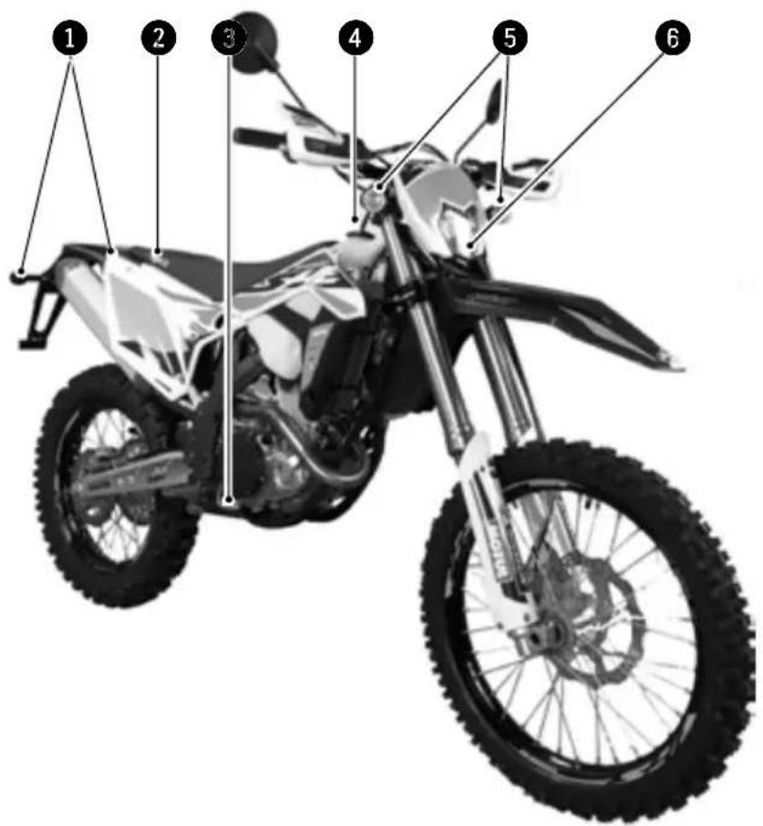
■ Right side
① Rear turn signals
② Saddle
③ Rear brake pedal
④ Fuel tank
⑤ Front turn signals
6 Headlight
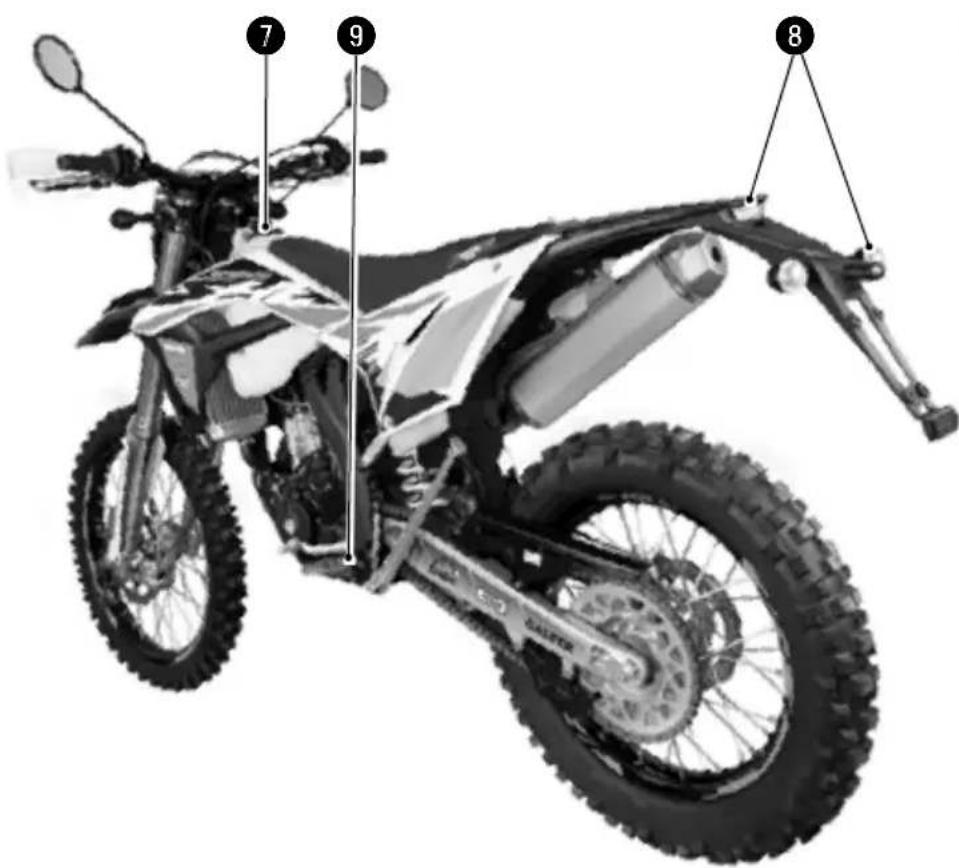
■ Left side
⑦ Fuel tank cap
8 Rear light (tail / brake light / plate light)
9 Gear selector pedal
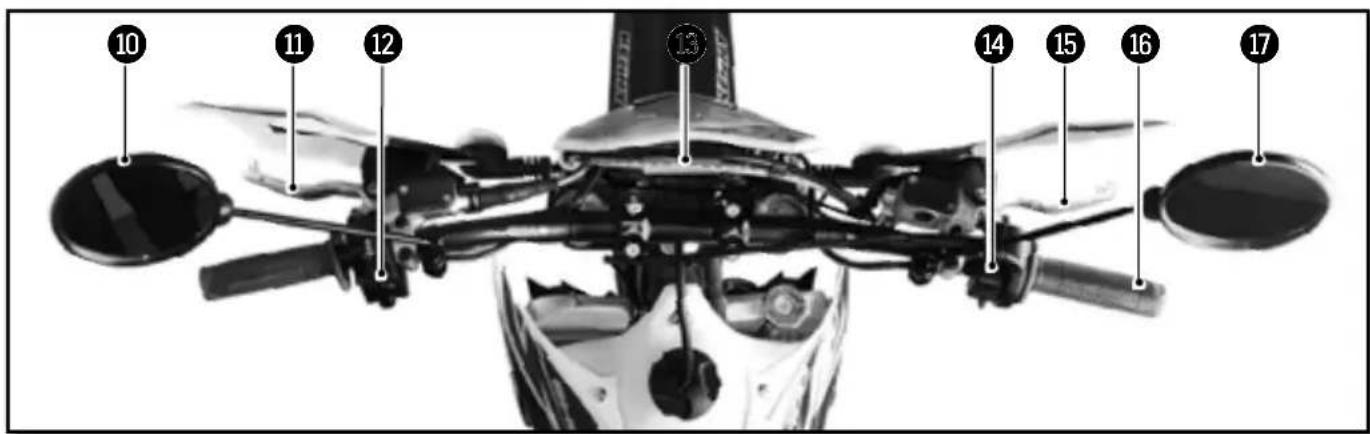
Description of the vehicle (continued)
Controls
10 Left mirror
11 Clutch lever
12 Left switch
13 Dashboard
14 Right switch
15 Front brake lever
16 Throttle grip
17 Right mirror
Engine serial number location
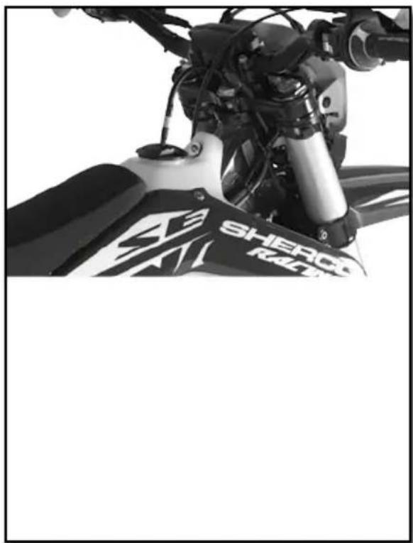
■ Vehicle serial number location
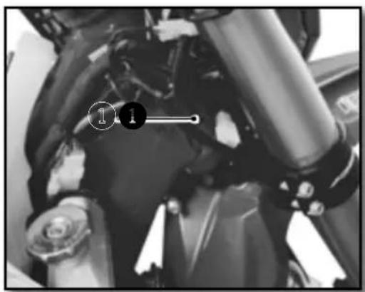
① The serial number of the vehicle is stamped on the right side of the steering tube.
■ Engine serial number location
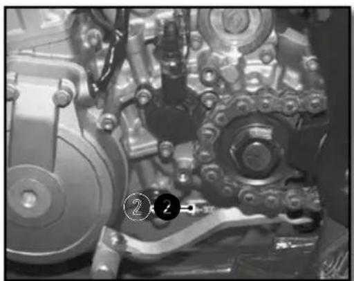
natural_image
Close-up of an internal mechanical assembly with gears and springs (no visible text or symbols)2 The engine serial number is stamped on the left side of the engine housing.
Control devices and controls
HAND OPERATED CONTROLS:
CLUTCH LEVER, FRONT BRAKE LEVER AND CONTROL SWITCHES
■ Clutch lever
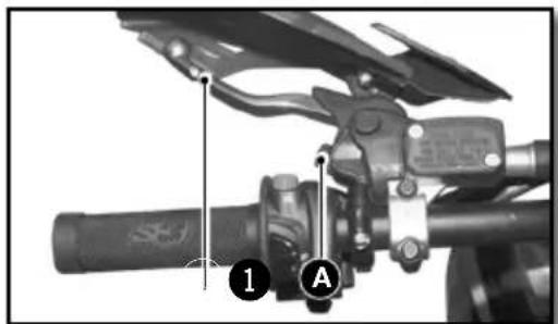
natural_image
Mechanical assembly diagram showing a lever mechanism with labeled parts (1 and A), no readable text or symbols present.The clutch lever ① is on the left handlebar and has an adjustment screw A
■ Front brake lever
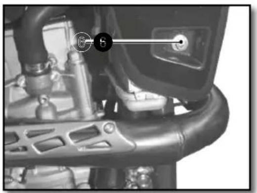
The front brake lever ② is on the right side of the handlebar and has an adjustment screw B
■ Left switch
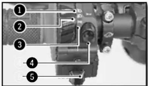
① High beam (Headlight)
② Low beam (Headlight)
③ Side light (Night))
4 Horn
⑤ Flashers
■ Light switch on / off
Two possible positions:
Position ON ① : All lights are on.
Position OFF ② : All lights are off.
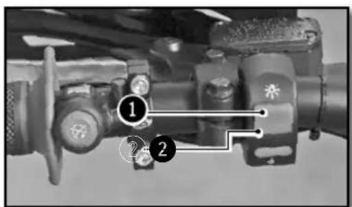
■ Rigth switch
1 Starter button
② Injection system mapping selection button
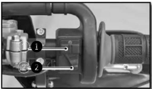
■ Dashboard
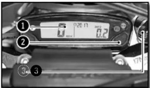
① Dashboard
② Mode selection button
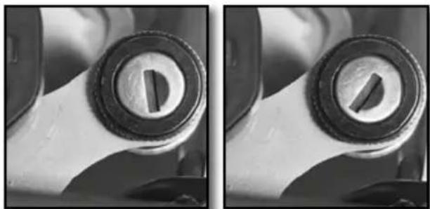
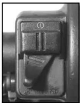
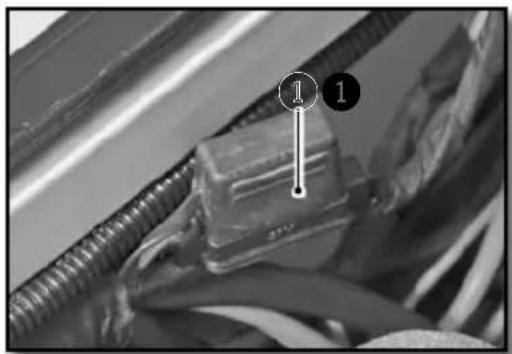
■ Key switch
natural_image
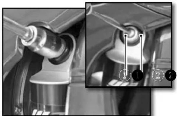
Close-up of a mechanical component with two circular features, one showing internal features and the other showing a slot (no text or symbols visible)Available with the homologation kit.
The main switch has two positions
Position ① The engine is off and can not be started.
Position ② The motor can be started.
■ Flasher switch
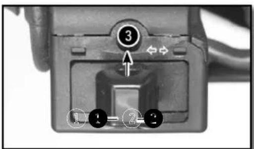
① Left turn position
② Right turn position
3 Off position G and D
Control devices and controls (continued)
■ KEYLESS System
The bike has a «keyless» system. It allows the bike to start without any key or ON/OFF switch. It automatically turns on and it turns off after 30 secondes of non use of the bike. Lithium-ion batteries are far lighter than lead batteries, have a low self-discharge rate, and have more starting power at temperatures over 15^ (60°F). At low temperatures, however, the starting power of lithium-ion batteries drops to below that of lead batteries.
Multiple starting attempts may be needed. Press the electric starter button for 5 seconds, and wait 30 seconds between attempts. The pauses are necessary so that the created heat can distribute through the lithium-ion battery and the battery is not damaged.
If the charged lithium-ion battery does not or only weakly turns over the electric starter when temperatures are below 15 °C (60 °F), then the battery is not faulty, but needs to be warmed up internally to increase its starting power (current output). The starting power increases as the battery warms up.
■ Motor emergency stop button
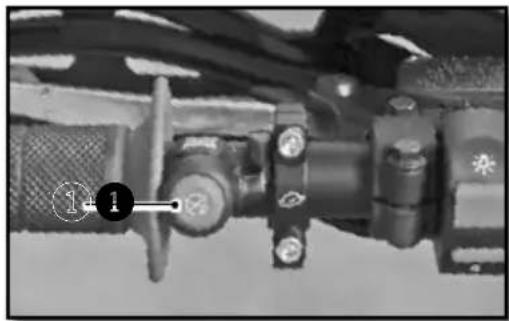
natural_image
Close-up of a mechanical assembly with no visible text or symbolsTwo possible positions:
The button is released: in this position, the bike can be ridden. The button is held down: in this position the motor is Off when released the motor can be restarted.
■ Injection system mapping switch
natural_image
Close-up of a mechanical switch or lever mechanism (no visible text or symbols)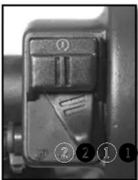
natural_image
Close-up of a mechanical component with numbered callouts (1-2) indicating specific parts, no readable text or symbols present.Position ① "Soft"
Position ② "Hard"
FOOT CONTROLS:
GEAR SELECTOR, SIDE STAND, REAR BRAKE
Gear selector
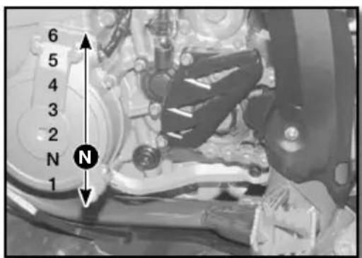
The drawing shows the path of the gear selector for each of the 6 speeds.
■ Footbrake
natural_image
Close-up of a mechanical component with no visible text or symbols① Rear brake control
■ Side stand
natural_image
Close-up of a mechanical assembly with visible gears and chains, no text or symbols presentRemove the rubber safety latch ①, using your foot on the shaft unfold it until it supports the weight of the bike.
WARNING
- The stand has a security system which automatically folds the stand when the bike is moved into an upright position.
- The stand has been designed to withstand the sheer weight of the bike.
Control devices and controls (continued)
MOTORCYCLE COMPUTER INSTRUCTIONS

CAUTION
In order to avoid any water ingress, keep a minimal washing distance of 20cm.
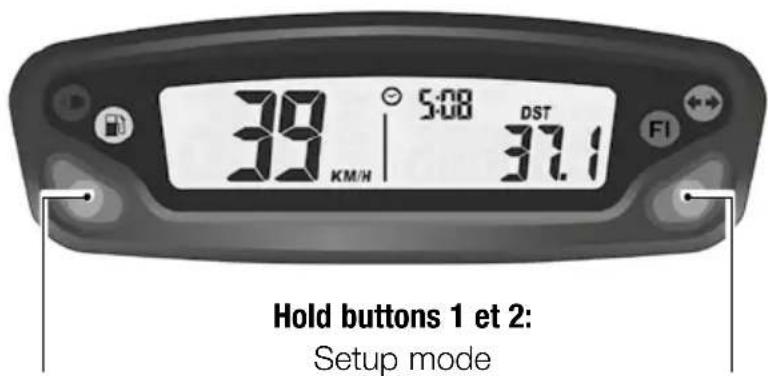
Button 1:
Change screens 1,2,3
Hold button 1:
Screen 1: DST Adjust
Screen 2: DST2 Adjust
Button 2:
Change screens 1,2,3
Hold button 2:
Screen 1: Reset DST
Screen 2: Reset DST2
Screen 3: Reset MAX/AVG
Screen 1: Speed, Clock, Distance 1 Screen 2: Speed, Clock, Distance 2
Screen 3: Alternating AVG/MAX speed, Accumulated run time, ODO

Turn indicator

High beam

Fuel injection (MIL): EFI problem

Low fuel
■ Mode buttons
The vehicle doesn't need to be switched on
Left button:
Switch between the three display screens Enter adjustable trip distance mode ( DST and DST2)
Decrement distance while in adjustable distance mode
Right button:
Switch between the three display screens Resets Trip distance 1, Trip distance 2, maximum and average speed (when pressed and held for three seconds) Increments distance while in adjustable distance mode
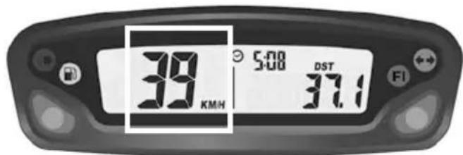
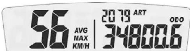
Fig 1 SPD function
![56 MAX KMH 20 TO ART [0] [3] ODO 34800.6 FI](/content/2026/03/559736/images/1879eb947bb0c6f09a06dad85d9c90c583750ac3ad3eaaaeb0f00324687c482e.jpg)
Fig 2 MAX speed function
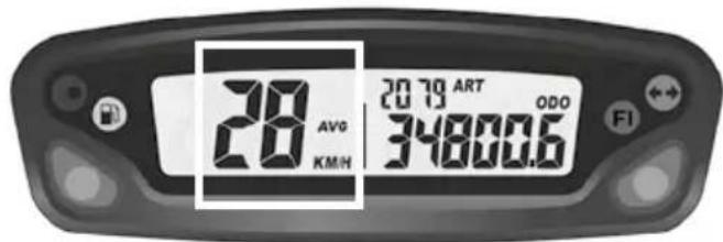
Fig 3 AVG function
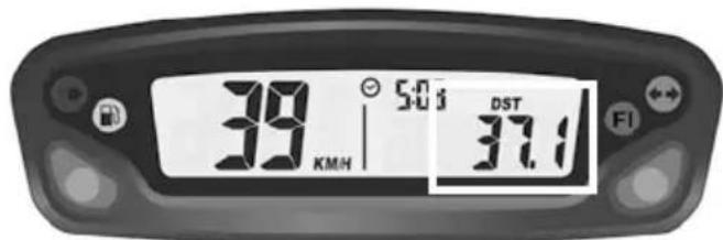
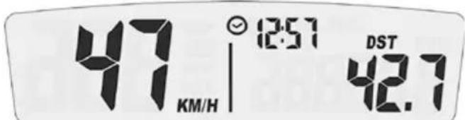
Fig 4 DST function
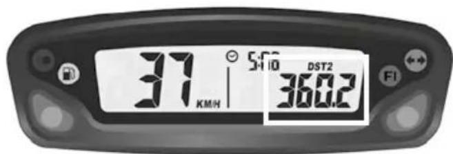
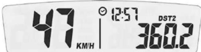
Fig 5 DST2 function
SPD function Current speed (screens 1 and 2):
displays the current speed of the vehicle.
The speed can be displayed in km/h (default) or mph. (p.81)
MAX speed (screen 3): displays the maximum speed since the last reset was performed. The maximum speed can be displayed in km/h (default) or mph. (p.81)
Reset to 0 → MAX Function → Hold the right Button down for 3 seconds → 0 → Reset to 0 done
AVG function Average speed (screen 3): displays the average speed of the vehicle since the last reset was performed.
The average speed is displayed in the chosen units, km/h (default) or mph (p.81)
Reset to 0 → AVG Function → Hold the right Button down for 3 seconds → 0 → Reset to 0 done
DST function (screen 1): displays the mileage traveled by the vehicle since the last reset was performed.
The distance is displayed in the selected units, km/h (default) or mph (p.81)
Reset to 0 → DST Function → Hold the right Button down for 3 seconds → 0.0 → Reset to 0 done
DST2 function (screen 1): displays the mileage traveled by the vehicle since the last reset was performed.
The distance is displayed in the selected units, km/h (default) or mph (p.81)
Reset to 0 → DST2 Function → Hold the right Button down for 3 seconds → 0.0 → Reset to 0 done
Control devices and controls (continued)
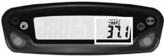
Fig 6 Adjustable trip distance function
DST and DST2 can be incremented or decre- mented by the user
DST set up (screen 1) → Hold the left Button down for 3 seconds → «DST» icon will flash → Hold left Button to decrement/ Hold the right Button to increment → back to screen 1
DST2 set up (screen 2) → Hold the left Button down for 3 seconds → «DST2» icon will flash → Hold left Button to decrement/ Hold the right Button to increment → back to screen 2
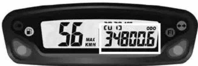
Fig 7 ODO function
ODO function Odometer (screen 3): displays the total mileage traveled by the vehicle.
The total distance is displayed in the selected units, km/h (default) or mph (p.81)
This information can not be reset to 0.
Beyond 399 999 km (or miles), the counter goes back to 0.
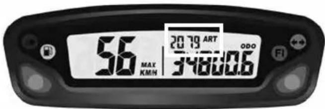
Fig 8 ART function
ART function Accumulated Ride Time (screen 3):
displays the hours of operation of the vehicle. This information can not be reset to 0.
Until 99h59min → displayed in one minute increments
After 99h59min up to 9999h → displayed in one hour increments
If the unit should reach 9999 hours of accumulated ride time, the display will stop incrementing, and will remain at that number.
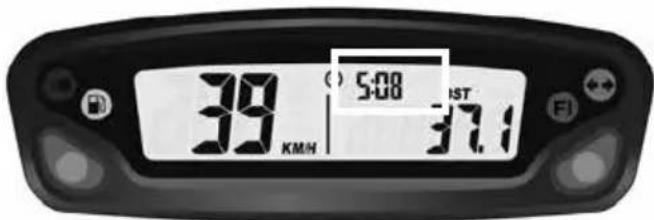
Fig 9 Clock function
Clock function (screens 1 et 2): displays clock information

Fig 11 Low battery/ Low battery error function
Low battery/ Low battery error function:
->When the battery voltage drops to less than 2.40V, the LO battery warning will turn on.
->When the internal battery is critically low, the unit will only display a blinking «LO» icon.
■ Set up menu
| Left and right buttons pressed simultaneously for 3s activates the Set up mode | |
| Left button Right button | |
| Toggle between M/H and KM/H settingsToggle between 24 Hour et 12 Hour | |
| Decrement time of day valueDecrement maintenance reminder value | Increment time of day valueIncrement maintenance reminder value |
The meter will automatically advance from one setting option to the next, after 5s of no button activation
| UNIT(Unit type) | LIFE(Wheel circumference) | PPr(Pulse per revolution) | (Clock format) | (Clock setup) | (Maintenance reminder) |
| Miles or KmDefault: kmDo not modify these settings | 12 or 24hDefault: 24h | Clock setup Maintenance reminder setting ( in hours)Default setting:5h (first oil change) | |||
Maintenance reminder: allows user to define a countdown for maintenance operations.
When the maintenance countdown gets to zero, the maintenance icon will appear on the LCD.
Displaying the remaining accumulated ride time : From main screen -> hold the left button down for 3 seconds -> the remaining value is displayed -> no button activation -> back to screen 3.
Note :
If the maintenance reminder is turned off, the information displayed on the screen will be OFF.
Resetting the remaining accumulated ride time : From main screen, hold the left button down for 3 seconds -> the remaining value is displayed -> hold the right button down for 3 seconds -> the maintenance reminder is reset to zero (will begin the countdown again according to the maintenance interval already chosen in the set up menu).
Control devices and controls (continued)
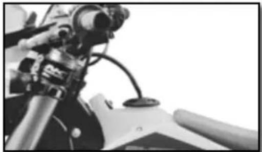
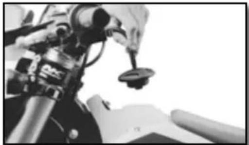
OPENING AND CLOSING THE FUEL TANK
Fuel
natural_image
Close-up of a motorcycle's front wheel and suspension components (no visible text or symbols)Use only unleaded fuel with an octane index of at least 95.
Filler cap
natural_image
Close-up of a robotic arm gripping a small object, possibly a sensor or device, with no visible text or symbols.Open : Turn the cap counterclockwise. The opposite direction to the hands of a watch. Close : Turn the cap clockwise. The same direction as the hands of a watch.
Riding the motorcycle
■ Cold engine starting
- Make sure the gear selector is in neutral.
- Start the engine by pressing the starter button, with the throttle closed.
- Allow the engine to warm up for a few minutes.
■ Hot engine starting
Follow the instructions above without Step 3.
■ Shifting gears
- The positions of the gear selector are shown on page 77.
- To find the neutral position, press the selector down into first gear (a resistance will be felt), then move the selector up slightly.
Riding the motorcycle (suite)
- Close the throttle before changing gears.
- Engage the lowest gear.
- Partially open the throttle while engaging the clutch.
Parking
- Stop the bike with the stop button. The keyless system will automatically switch off the ignition after 30 seconds of non use of the bike.
Become familiar with all of the controls and their functions before using the vehicle.
Safety information
- Do not drive after consuming alcohol.
- Wear a helmet when using the vehicle.
- Keep the machine in good working order and maintain it properly so that it is reliable and safe for use.
- Gasoline is flammable, refuel the motorcycle when the engine is stopped.
- Exhaust fumes are toxic, you should never start the engine in a closed building.
- Always park the vehicle on a flat hard surface, do not park the vehicle on a slope or on soft ground. Always control the balance of the vehicle.
- Check the following every day before riding the motorcycle:
Tires : Wear and pressure
Engine oil : Level (
p.88)
Gasoline : Check the level and make sure there are no leaks
Transmission chain Properly lubed and adjusted (
p.104)
Direction of travel : Make sure that your path is clear
Brakes : Operation, fluid leakage, brake pad wear (
p.113 to p.116)
Throttle: Proper operation (
p.87)
Clutch : Proper operation (
p.105)
Electrical Equipment : Operation of the horn and lights (
p.74 and p.76)
Components (nut, bolts ...): Verify that all components of the vehicle are properly tightened (p.126)
If you experience a problem with any of the components of the motorcycle, consult the Service and Adjustments section of this manual or contact a Sherco dealer.
Cooling System
SERVICING THE COOLING SYSTEM
natural_image
Close-up of a mechanical assembly with labeled parts (1 and 2), no readable text or symbols present.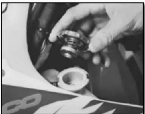
natural_image
Close-up of hands assembling a mechanical component (no visible text or symbols)
natural_image
Two identical cylindrical objects with vertical stripes, one emitting a droplet (no text or symbols)Moto horizontal

WARNING
- The hot liquid can cause severe injuries.
- The coolant is harmful
- After contact with skin or eyes, or ingestion, or injuries caused by hot liquids: Consult a physician
- Use protective gloves.
- Do not replace the coolant with water or other not approved fluids: it could damage your engine.
- Follow these procedures carefully and always fill the engine with coolant when the engine is cold.
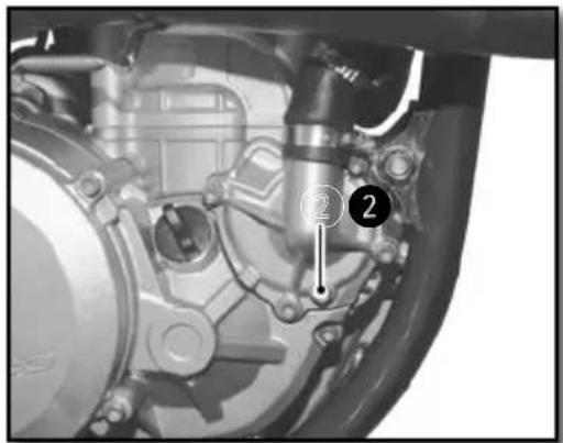
Place the bike upright on a horizontal surface.
- Remove the cap 1.
- Remove the bleed screw ②.
Fill the radiator full so that there is no air in the system.
| Approved Coolant | Motul® Motocool Factory Line -35°C |
Replace the screw 2.
| RadiatorBleed screw | M6X8 8Nm |
Fill the coolant to the top of the radiator.
Replace the cap ① and check to make sure it is tight.

WARNING
It is important to follow this procedure.
The lack of fluid, or the presence of a pocket
of air left in the radiator can cause
serious damage to the engine.
natural_image
Close-up of mechanical components including gears and linkages (no visible text or symbols)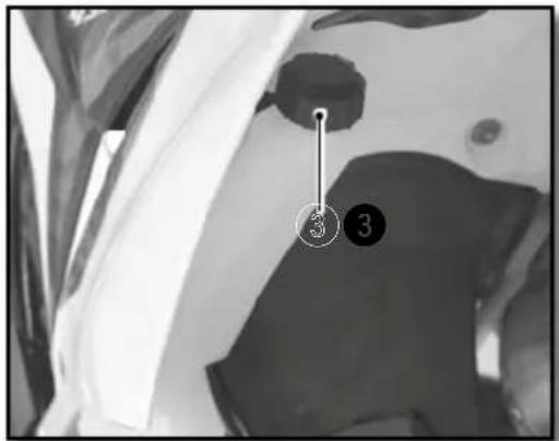
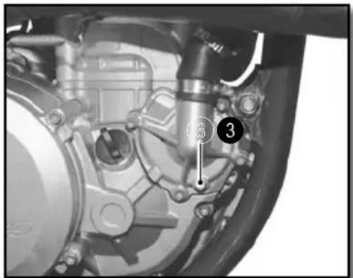
Check the fluid level in the expansion container. The liquid should reach the level on the container where it indicates "LEVEL"
If the level is not correct, unscrew the cap ③ Fill with fluid until it reaches the LEVEL mark.
| Coolantde refroidissement | Motul® MotocoolFactory Line -35°C |
Replace the cap ③.
WARNING
Make sure the bike is vertical and on a horizontal surface.
-Place a container under the bike
-Remove the cap ① and screw ③
-Allow the coolant to drain.
NOTE
To protect the environment deposit the drained coolant at an approved collection center.
Cooling System (continued)
FILLING THE COOLANT
- Remove the bleed screw ^2 located on the left side of the radiator
- Pour the coolant into the radiator through the cap ①.
| Coolant Motul | ® MotocoolFactory Line -35°C |
- Allow the coolant to flow through the screw until there are no bubbles, replace the screw using a new gasket.
| Radiator bleed screw | M6X8 8Nm |
- Continue filling.
- Fill until the coolant reaches the level (approximately 1.1 liters)
- Put the bike on the side stand and follow the rest of the filling procedure (p.84)
Motor settings
CHECKING THE PLAY IN THE THROTTLE CABLE
■ Checking the throttle cable play
natural_image
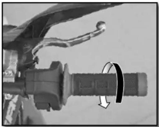
Close-up of a bicycle brake lever with a curved arrow indicating rotational motion (no text or symbols visible)With the handlebars facing straight ahead, check that the throttle twist grip functions properly.
Throttle cable play 2....4mm
If the cable play is not correct, adjust the accelerator throttle cable play. (p.87)
Start the bike and let it run at idle. Turn the handlebars and check that the idle speed is constant. If the speed changes, readjust the play in the throttle cable. (p.87)
■ Adjusting the play in the throttle cable
natural_image
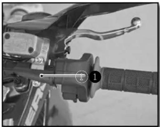
Close-up of a motorcycle's brake lever and grip (no visible text or symbols)Adjust the throttle cable play at the location shown ① with the adjuster.
If this is not enough, adjust the play directly on the throttle body.
Engine maintenance
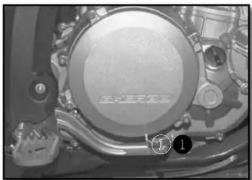
CHECKING THE ENGINE OIL LEVEL
natural_image
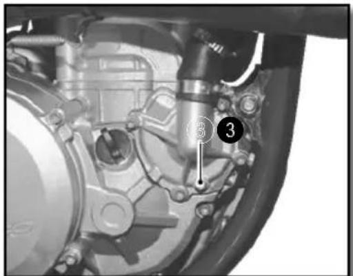
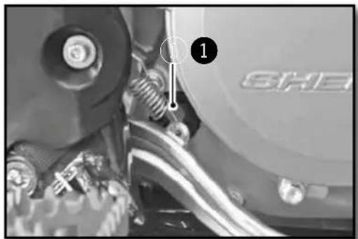
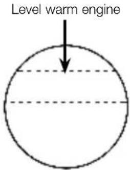
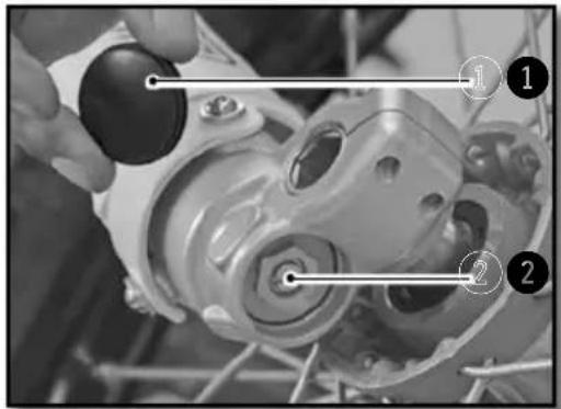
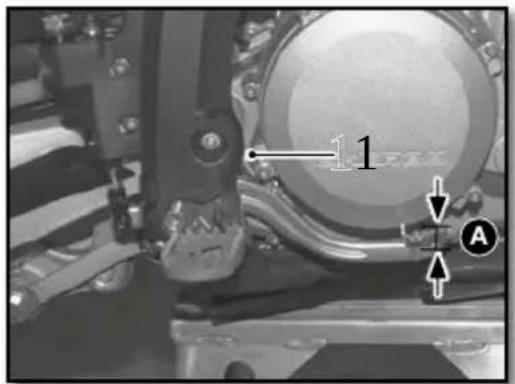
Close-up of a mechanical assembly with labeled parts (1) and 'SHE' on the wheel, no readable text or symbols beyond labels.- Make sure that the bike is on its two wheels, vertical and on a horizontal surface.
- Check the engine oil level by viewing the sight gage located on the clutch housing ①.
- Adjust the level according to the diagram shown below.
natural_image
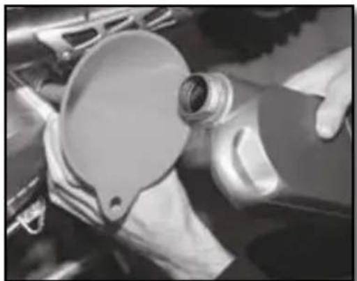
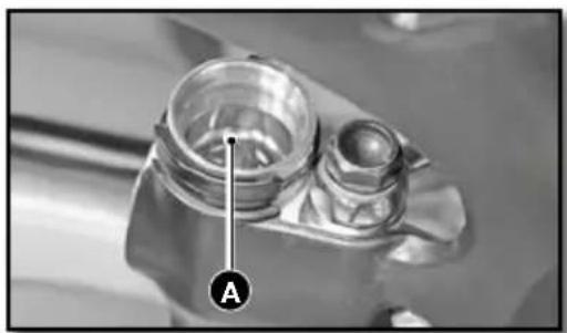
Close-up of a mechanical component with a hand adjusting parts, no visible text or symbolsIf necessary add oil to achieve the correct oil level.
- Unscrew the engine oil filler cap ② located on the clutch housing
natural_image
Close-up of hands operating a car tire hood with a circular dial (no visible text or symbols)Topping up the engine oil
Engine Oil SAE 10w60

WARNING
- Improper oil level can damage your engine.
- Do not use your bike if the level is below the minimum.
Engine maintenance (continued)
DRAINING THE ENGINE OIL AND REMOVING THE OIL FILTER

- When draining the oil the engine should be warm

WARNING
Use protective gloves
- Position the motorcycle upright on a level surface.
- Place a container under the bike to catch the old oil.
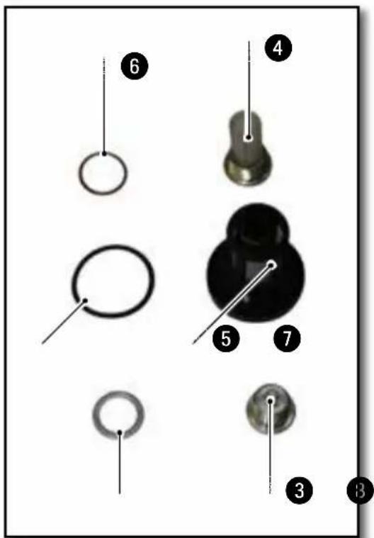
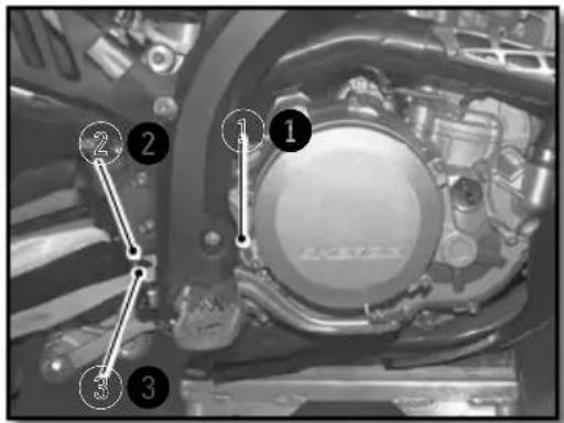
- Remove the drain plug① and ②
- Remove the magnetic drain plug 3
- Remove the pre-filter ④ and ⑤
- Allow the oil to drain
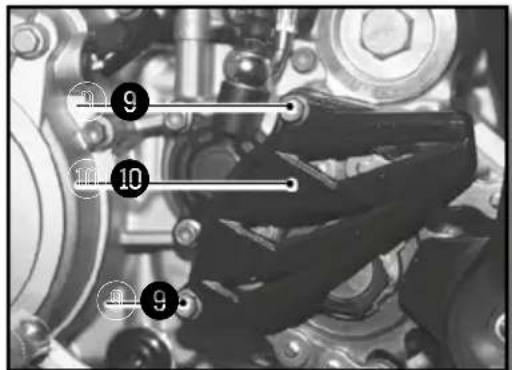
- Remove the screws ⑨ and remove the chain guard ⑩
Engine maintenance (continued)
natural_image
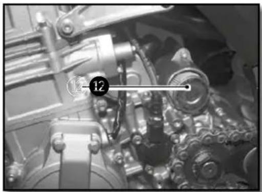
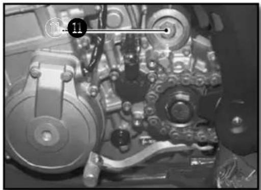
Close-up of a mechanical assembly with gears and shafts (no visible text or symbols)- Remove the oil filter cover ⑪.
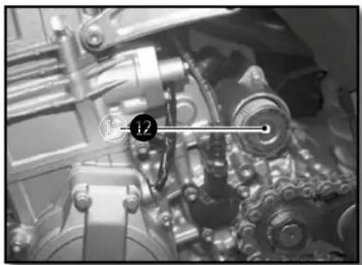
- Use a hook to remove the oil filter 12.
- Let the oil drain.
- Clean the drain plugs①, ② and ③ with a degreaser.
- Clean and inspect the pre-filters④ and ⑤ and change them if necessary.
natural_image
Close-up of mechanical components with no visible text or symbolsREFILLING THE ENGINE WITH OIL
natural_image
Close-up of mechanical components with no visible text or symbols
natural_image
Close-up of mechanical components with no visible text or symbols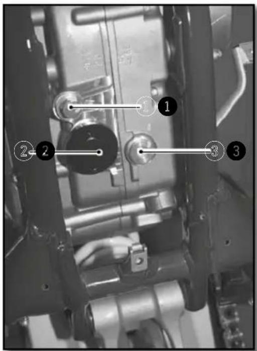
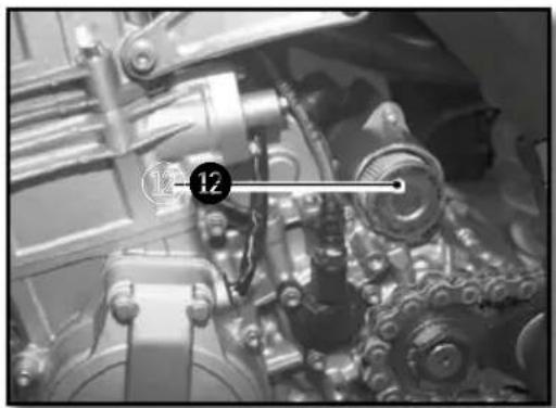
- Install a new oil filter ^12 , install in the direction shown in the photo.
- Install the cap ⑪ using a new O-ring.
| Oil Filter cap M45 15Nm |
- Install the plug ③ using a new gasket.
| Magnetic drain plug | M12 15Nm |
- Install the pre-filters ^4 and ^5 and drain plugs ^1 and ^2 as shown in photo n°4.
| Drain plug 1 | M18 15Nm |
| Drain plug 2 | M32 20Nm |
- Remove the engine oil filler cap②. (p.88)
- Fill the engine with oil
| Motor oil 1,1l SAE 10w60 |
- Install the engine guard. (p.105)
- Check the oil level in the sight gage. (p.88)
- Add additional oil if necessary.

NOTE
The oil filter 12 should be replaced at each oil change.

WARNING
To protect the environment, oil, oil filters and used material must be deposited in a collection center and not down the drain or in the wild.
Adjusting the chassis
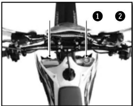
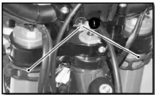
HANDLEBAR POSITION
natural_image
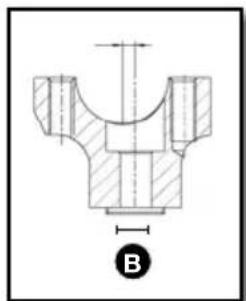
Technical drawing of a mechanical component with cross-sectional hatching and dimension line (no text or symbols)
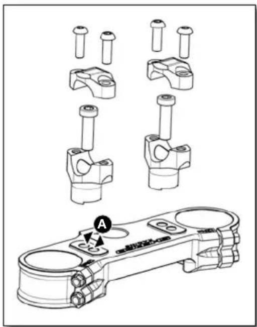
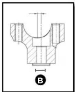
The triple clamps have two holes separated by a distance A.
| Distance between holes A 13mm | |
| The handlebar clamps are offset by a distance B | |
| Handlebar offset B 4mm | |
The bike comes standard with the handlebars in the rear most position.
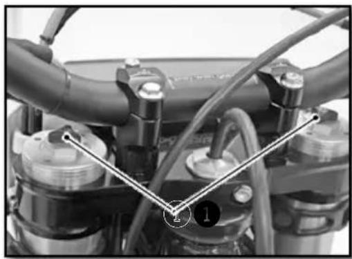
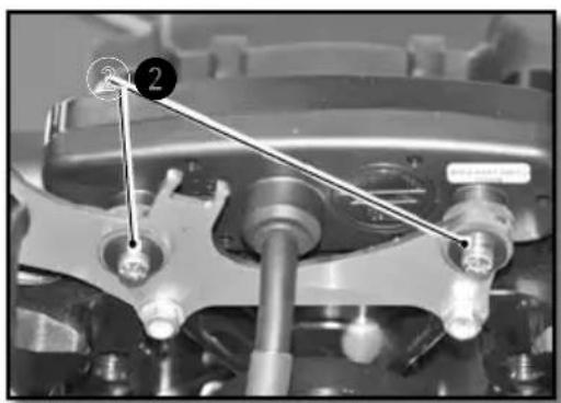
Remove the four screws ①. Remove the handlebar top clamps and remove the handlebar.
Remove the two screws ②. Remove the lower clamps and place them in the desired position.
| Handlebar lower clamp | M10x35 | 40Nm Loctite ^ 243 ^TM |
Replace the handlebars and top clamps. Replace the four screws ① and tighten evenly.
| Handlebar clamps fixing screws | M8x25 24Nm |
The handlebars can be rotated forward and rearward in the clamps.
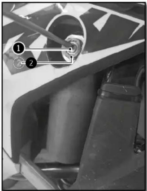
ADJUSTING THE STEERING ANGLE
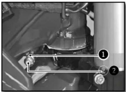
The steering angle can be changed using the set screws located on the bottom of the steering column.
Loosen the nut ① and tighten the screw ② until you have the steering angle desired.
Tighten the nut and do the same operation on the other side.
| Steering angle lock nut | M8 20Nm |
BASIC SETTING OF THE CHASSIS ACCORDING TO THE RIDER WEIGHT
| Standard weight of the-rider (with equipment) | 75 à 85kg |
If the weight of the rider is above or below the standard, compensate by changing the stiffness of the springs (forks and shock).
SETTING THE FORK COMPRESSION
WP

natural_image
Close-up of a motorcycle's front wheel and side-mounted sensors (no visible text or symbols)KAYABA
1
Screws ② determine the behavior of the fork when it is compressed. Turning in the screw-clockwise increases the hydraulic force (and vice versa).
Remove the caps ① located at the lower end the fork.
Turn screw ② clockwise to the stop and go back the number of clicks required.
| Setting compressionWP suspensionXPLOR ∅48mm(racing) | Comfort 18 clicks |
| Standard 15 clicks | |
| Sport 12 clicks | |
| Setting compressionKAYABA (factory) | Comfort 20 clicks |
| Standard 12 clicks | |
| Sport 8 clicks | |
Replace the cap 1.
Adjusting the chassis (continued)
FORK REBOUND ADJUSTMENT
natural_image
Close-up of a motorcycle engine bay with hoses and valves (no visible text or symbols)
natural_image
Close-up of mechanical components with a numbered annotation (1) and a diagonal line, no readable text or symbols present.The adjusting screws 1 determine the behavior of the fork when it rebounds. Turning the screws clockwise increases the hydraulic force (and vice versa).
The adjustment screws 1 are located at the end of the upper fork legs.
Turn the screw ① clockwise to the stop then go back the number of clicks required.
| Setting rebound WP suspension XPLOR ∅48mm (racing) | Comfort 18 clicks |
| Standard 15 clicks | |
| Sport 12 clicks | |
| Setting rebound KAYABA (factory) | Comfort 18 clicks |
| Standard 12 clicks | |
| Sport 10 clicks | |
SETTING THE FORK SPRING PRELOAD
natural_image
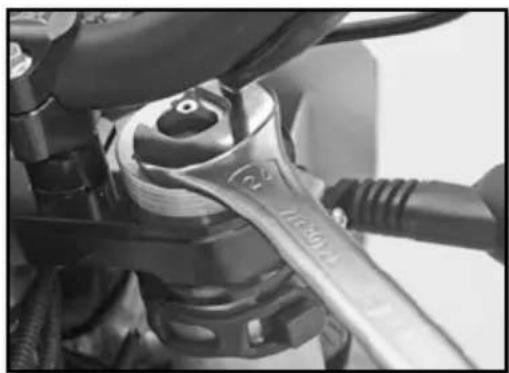
Close-up of a mechanical wrench tool interacting with a mechanical component (no visible text or symbols)The adjusting nut allows the preload of the Spring to be adjusted. Turning the nut clockwise increases the preload (and vice versa).
Turn the nut with a wrench counterclockwise until it stops and then turn it the number of turns required.
| Suspension spring preload WP XPLOR ∅48mm (racing) | Comfort 0 turn |
| Standard 0 turn | |
| Sport 2 turns |
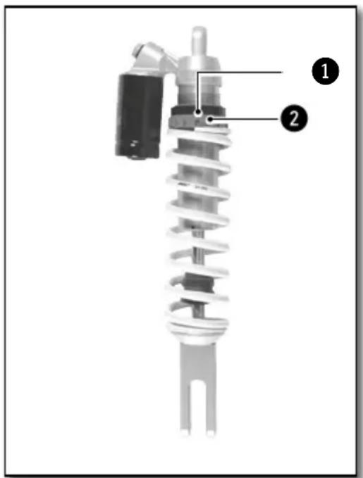
ADJUSTING THE REAR SHOCK LOW-SPEED COMPRESSION SETTING
WP
The adjusting screw 1 determines the slow speed behavior of the rear shock (sensitivity Turning the screw clockwise increases the hydraulic force (and vice versa).
Turn the screw ① clockwise with a screwdriver until it stops and then turn it back the number of clicks required.
Do not loosen the nut 2.

KAYABA
REAR SHOCK WP (RACING)
| Low-speed compression setting | Comfort 20 clicks |
| Standard 15 clicks | |
| Sport 12 clicks |
REAR SHOCK KAYABA (FACTORY)
| Low-speed compression setting | Comfort 20 clicks |
| Standard 14 clicks | |
| Sport 12 clicks |
Adjusting the chassis (continued)
ADJUSTING THE REAR SHOCK HIGH-SPEED COMPRESSION SETTING
natural_image
Mechanical assembly diagram showing two views of a car wheel and a shaft (no text or symbols)WP
The adjusting screw ① determines the high speed behaviour of the rear shock (big hits). Turning the screw clockwise increases the hydraulic force (and vice versa).
Turn the screw 1 clockwise with a socket wrench until it stops and then back the number of clicks required.
Do not loosen the nut 2
natural_image
Close-up of a motorcycle's front wheel and suspension components (no visible text or symbols)KAYABA
REAR SHOCK WP (RACING)
| High-speed compression setting | Comfort 2,5 turns |
| Standard 2 turns | |
| Sport 1,5 turns |
REAR SHOCK KAYABA (FACTORY)
| High-speed compression setting | Comfort 2,5 turns |
| Standard 1,5 turns | |
| Sport 1 turn |
REBOUND DAMPER
natural_image
Close-up of mechanical components with no visible text or symbolsThe adjusting screw 1 determines the Shock rebound behavior. Turning the screw clockwise increases the hydraulic force (and vice versa).
Turn the screw ① clockwise to the stop then go back the number of clicks required.
REAR SHOCK WP (RACING) REAR SHOCK KAYABA (FACTORY)
| Rebound damping | Comfort 15 clicks | Rebound damping | Comfort 15 clicks |
| Standard 13 clicks | Standard 13 clicks | ||
| Sport 11 clicks | Sport 11 clicks |
SETTING THE DEPRESSION OF THE REAR SHOCK WITH NO LOAD
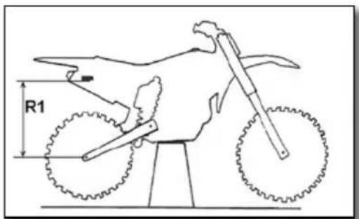
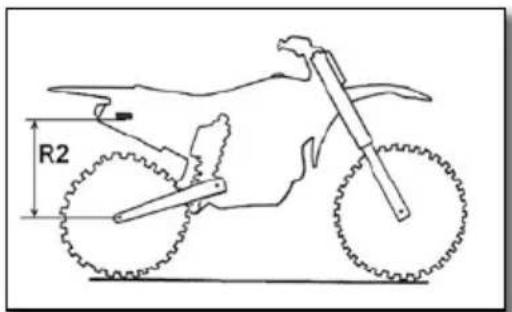
With the bike on an appropriate stand
Measure the dimension R1 between a fixed point on the chassis and the rear axle.
With the bike setting on its wheels
Measure the dimension R2 from the same fixed point on the chassis and the rear axle. The static deflection is the difference between R1-R2.
Static deflection 30mm
If the static deflection is not correct, adjust the preload of the shock (p.98)
SETTING THE REAR SHOCK SAG
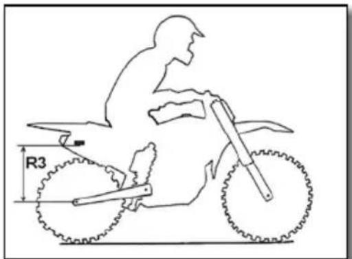
With the rider on the motorcycle
Measure the dimension R3 between the same fixed point on the chassis and the rear axle. The sag is the difference between R1-R3.
| Sag 110 mm |
If the sag is not correct, change the spring.
( p.98)
Adjusting the chassis (continued)
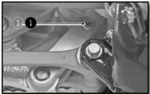
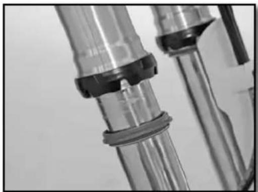
CHANGING THE PRELOAD OF THE SHOCK
Remove and clean the rear shock unit (p.107). Loosen the collar ①.
Loosen / tighten the red plastic ring ② depending on the length required.
| Indications | Loosening one turn | Decreases the overall length by 3mm. |
| Tightening one turn | Increases the overall length by 3mm. |
Tighten the collar ① (tightening torque: 5 Nm)
Reinstall the shock (p.108
Recheck the settings (p.97)
REAR SHOCK KAYABA (FACTORY)
Remove and clean the rear shock unit.
Loosen the collar 1.
Loosen / tighten the red plastic ring ② depending on the length required..
| Indications | Loosening one turn | Decreases the overall length by 4mm. |
| Tightening one turn | Increases the overall length by 4mm. |
Tighten the collar ① (tightening torque: 5 Nm).
Reinstall the shock
Recheck the settings
CHANGING THE SHOCK SPRING
Remove and clean the rear shock unit (p.107)
Select and install a spring based on your weight.
| Spring Rate KAYABA WP | ||
| Rider Weight (with equipment) : 65-75 kg 48N/mm | 51N/mm | |
| Rider Weight (with equipment) : 75-85 kg 50N/mm | 54N/mm | |
| Rider Weight (with equipment) : 85-95 kg 54N/mm | 57N/mm | |
Reinstall the shock.
Adjust the sag (p.97)
Adjust the static deflection (p.97)
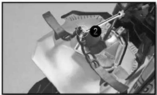
Chassis maintenance
REMOVING THE SADDLE
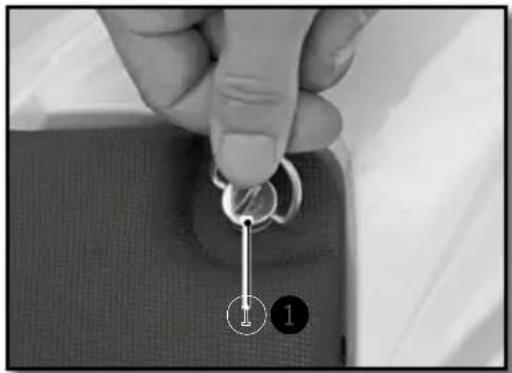
natural_image
Close-up of a hand holding a key inserted into a fabric pocket, with two numbered callouts (1 and 2) pointing to the key area.Turn the Dzeus fastner ① a quarter turn counterclockwise to release the saddle.
Remove the seat by pulling it towards the back of the bike.
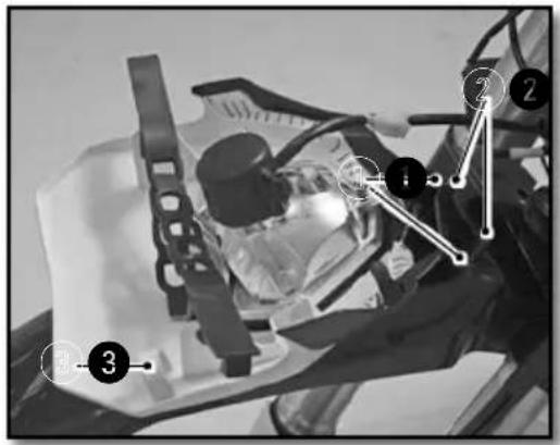
REINSTALLING OF THE SADDLE
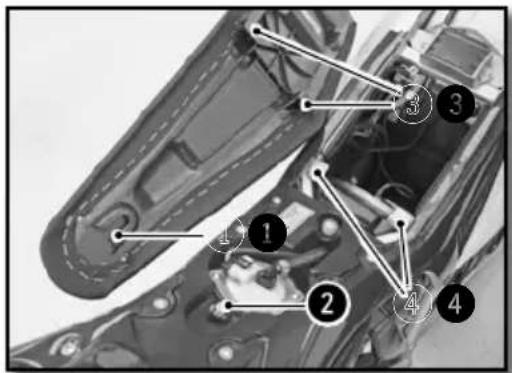
Install the saddle by sliding it forward, making sure that the slot ① in the seat pan engages the post ② in the reservoir. The ③ notches in the saddle must pass through the tabs on the subframe ④ that are provided for this purpose.
Lock the Dzeus fastner by turning it a quarter turn clockwise.
REMOVING THE AIR FILTER
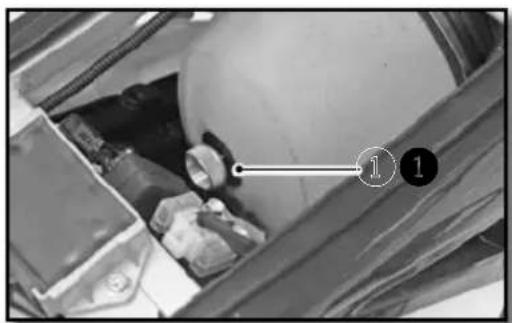
natural_image
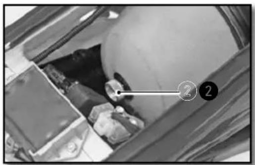
Interior view of a vehicle storage bay with visible battery and wheel (no text or symbols)The air filter is vital for the smooth operation of your engine. Maintenance is therefore essential.
A dirty air filter reduces the performance of your bike, increases fuel consumption and, at worst, impurities can pass into the engine and cause premature wear.
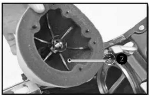
natural_image
Close-up of a mechanical component with visible internal blades and a numbered annotation (2) pointing to a specific part.Remove the seat (p.99)
Unscrew the thumb screw ①.
Remove the filter with the plastic carrier 2.
Separate the filter from its plastic holder.
Chassis maintenance (continued)
CLEANING THE AIR FILTER
Clean the foam air filter with a special liquid cleaner and let dry.

INFO
Do not clean the air filter with a solvent or gasoline.
| Air filter cleaner Motul | ® A1 Air Filter Clean |

INFO
Do not wring out the filter by twisting. Press only. Soak the air filter in an air filter oil.
| Air Filter oil Motul | ® A2 Air Filter Oil |
If necessary clean the inside of the air box with a cloth.
REINSTALLING THE AIR FILTER
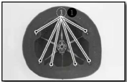
natural_image
Cross-sectional view of a mechanical component with numbered points (1 and 2) and internal lines, no readable text or symbols.Reposition the filter on its support.
Be sure to engage on all six tabs.
Apply a film of grease on the face of the filter element.
natural_image
Interior view of a vehicle showing engine compartment with numbered annotation (2) pointing to a component, no readable text or symbols present.Reinstall the filter and its support by taking special care to make sure it is centered. Refit the knurled screws ②.
Check to make sure the air filter is properly seated. Install the saddle (p.99)
REMOVING THE FUEL TANK


natural_image
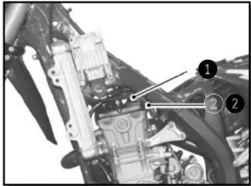
Close-up of a mechanical component with hoses and a labeled connector (no readable text or symbols)Remove the seat (p.99)
Unscrew the fuel tank fixing screws 1.
Disconnect the fuel pump electrical connector 2.
Remove the fuel hose by pressing the connector ③ and pulling on the hose ④.

WARNING
Attention, there is a risk of spraying fuel. do not put your face near the fuel line exit.
Prevent ingress of dirt in the gasoline fuel line. This can lead to a seizure of the injector.
Unscrew the screws ⑤ don the right and left radiator grill.
Remove the fuel tank by pulling upwards, provide lateral clearance by slightly moving the radiator grills. Use caution when removing the fuel tank and do not damage any of the fuel hoses or electrical connections.
Chassis maintenance (continued)
REINSTALLING THE FUEL TANK
Reassembly of the fuel tank.
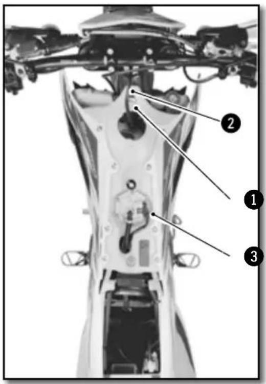
Be sure to correctly position the throttle ① and clutch cable ②.
Locate all of the fuel hoses / electrical connections under the fuel tank well.
Install the tank by moving the radiator guards away from the radiator to provide clearance for the fuel tank and makesure that all of the cables, wires and hoses are free, clear and not pinched.
Check the adjustment of the radiator guards in relationship to the fuel tank.
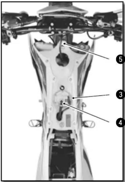
Connect the fuel line ③ and electric connection ④.
Install the fuel tank mounting screws ⑤ along with their rubber inserts.
Install the radiator grill mounting screws.
Chassis screws M6 10Nm
Reinstall the saddle (p.99)
PURGING THE AIR FROM THE FORKS
After some time of operation, the air accumulates under pressure in the fork.
Every 5 to 10 hours (depending on the riding intensity), it should be purged. With the fork cold and fully extended, loosen and then retighten both fork caps.
CLEANING THE FORK DUST SEALS
natural_image
Close-up of metallic cylindrical and mechanical components with no visible text or symbolsPlace the motorcycle on a suitable stand.
Remove the front wheel (p.109)
Remove the fork protectors. Slide the dust cover down. Clean and lubricate the dust cover and the fork tube.
Lubrifiant universel Motul® P4 EZ Lub
Reinstall the dust cover and clean off any left over oil.
Reinstall the fork protection.
Reinstall the front wheel (p.109)
Take the bike off of the stand.
CHECKING THE PLAY OF THE STEERING HEAD BEARINGS

natural_image
Side view of a modified off-road motorcycle with visible dynamics arrows indicating motion (no text or symbols)Place the motorcycle on a suitable stand.
Exert a back and forth force on the fork legs.
There should not be any play in the bearings in any direction in the steering bearings.
If there is play and / or resistance, adjust and / or change the bearings.
Adjust the bearing free play (p.104)
Take the bike off of the stand.
Chassis maintenance (continued)
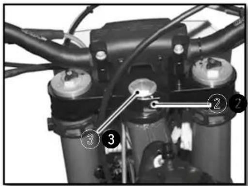
ADJUSTING THE STEERING HEAD BEARING PLAY
natural_image
Close-up of mechanical components with wires and a numbered marker (no visible text or symbols)Place the motorcycle on a suitable stand.
Loosen screws ① and ②
Loosen or tighten the nut ③ to adjust the steering bearing play.
| Steering nut M20 30Nm | ||
| Tighten the screws1 | ||
| Top fork screws M8x35 17Nm | ||
| WP top fork screws M8x35 15Nm | ||
Tighten screw 2
| Top clamping screw | M8x30 | 17Nm | Loctite®243TM |
Check the play of the steering head bearings. (▶ p.103)
Remove the bike from the stand.
The bearings should be greased at least once a year with a good quality grease.
CLEANING THE CHAIN
Regularly cleaning the chain considerably increases its service life.
Clean the chain and apply chain lubricant.
Chain Cleaner
Motul® C1 Chain Clean
CHECKING THE CHAIN TENSION
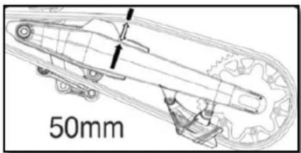
Place the motorcycle on a suitable stand
Push the chain up and measure the chain movement as shown in the diagram.
| Chain tension 50mm...53mm |
If the chain tension is not correct, see how to adjust the chain. (●p.105)
Otherwise, remove the bike from the stand.
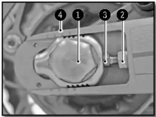
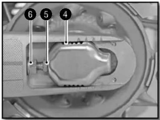
ADJUSTING THE CHAIN TENSION
natural_image
Mechanical assembly diagram showing a gear and housing component with a numbered marker (7) pointing to a specific part.ADJUSTING THE LEVER
natural_image
Close-up of a motorcycle's grip and lever mechanism, labeled with 'B' (no text or symbols on the diagram itself)WARNING
Improper chain tension can cause mechanical damage.
Place the motorcycle on a suitable stand.
Loosen nut 1
Loosen the nuts 2
Loosen or tighten the screws ③ until you have the correct chain tension.
Chain tension 50mm...53mm
Monitor the symmetry of the two sides by observing the position of the marks 4
Tighten the screws 5
Tighten the nut 6
Rear axle nut M24 100Nm
Remove the bike from the stand.
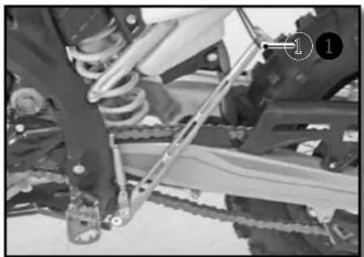
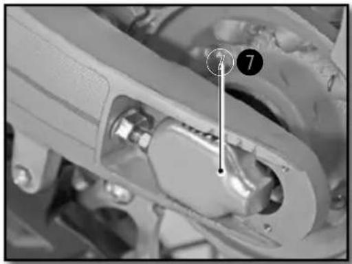
NOTE
The sliding piece ⑦ is designed to accommodate longer chains by turning it 180 degrees.
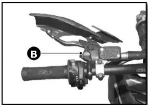
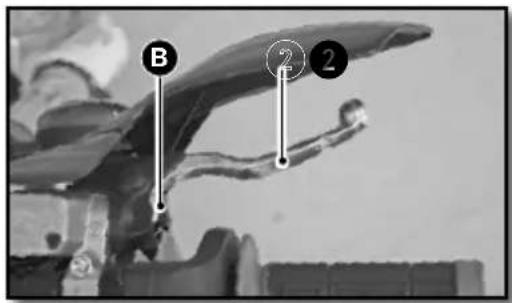
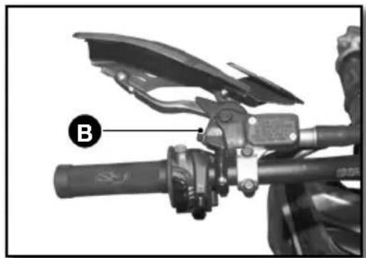
The position of the lever can be adjusted to meet the needs of the rider.
- Turn the knob Ⓑ clockwise to move the lever closer to the handlebar.
Chassis maintenance (continued)
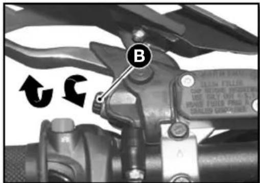
- Turn the knob B in the opposite direction to move the lever away from the handlebar.
Clutch lever free play A ≥3mm
CHECKING THE CLUTCH FLUID LEVEL

WARNING
- The hydraulic fluid is highly corrosive it can be dangerous to the skin.
- Read the recommendations on the container.
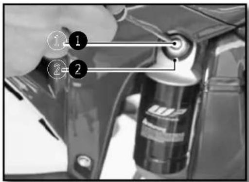
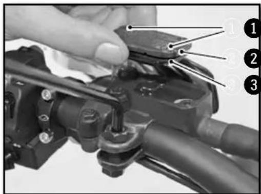
Position the master cylinder horizontally.
- Remove the two screws ^1 , the cover ^2 and the membrane ^3
- Check the fluid level and fill if necessary.
Level of brake fluid below the top of the reservoir.
4mm
Motul® RBF 700 Brake fluid DOT 4
- Reinstall the lid with the membrane and the screws.
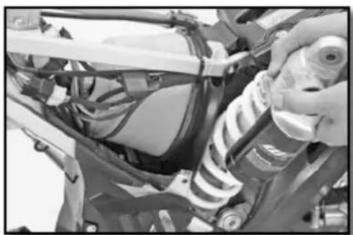
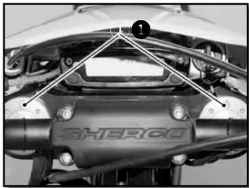
REMOVING THE REAR SHOCK
natural_image
Close-up of a mechanical assembly with numbered annotations (1 and 2) pointing to components, no readable text or symbols present.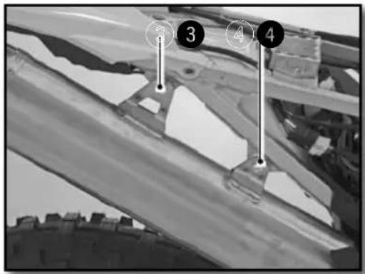

natural_image
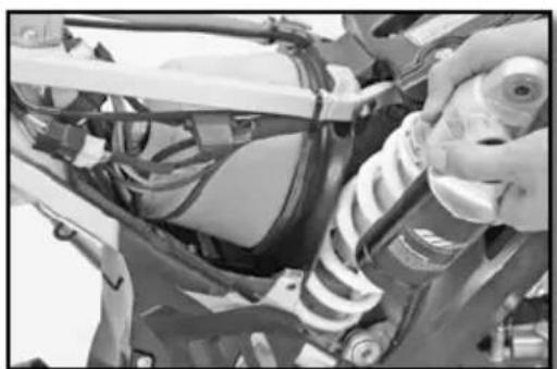
Close-up of a mechanical assembly with springs and wiring (no visible text or symbols)Place the motorcycle on a suitable stand.
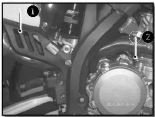
Remove the right side plate.
Remove the spring ① from the muffler and spring ② from the intermediate exhaust pipe.
Remove the screws ③ and ④ and the muffler along with the intermediate exhaust pipe.

WARNING
Do not remove the muffler after operating the motor-cycle. It can behot and there is a risk of being burned.
Remove the shaft 5.
Remove the screw 6.
Remove the top screw of the shock.
Remove the shock from the top.
Chassis maintenance (continued)
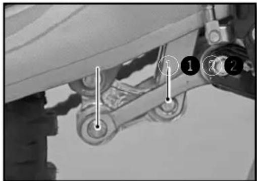
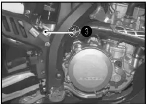
REINSTALLING THE REAR SHOCK
natural_image
Close-up of a mechanical assembly with numbered components (3) and no visible text or symbols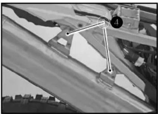
natural_image
Black-and-white aerial view of a building with visible roof and window, marked points 3 and 4 (no text or symbols)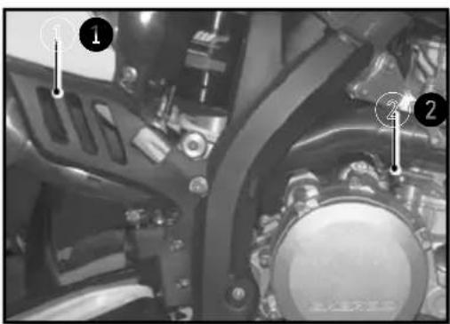
Install the shock from the top.
Install the top screw and tighten.
| Upper shock screw | M10 40Nm Loctite®2701 |
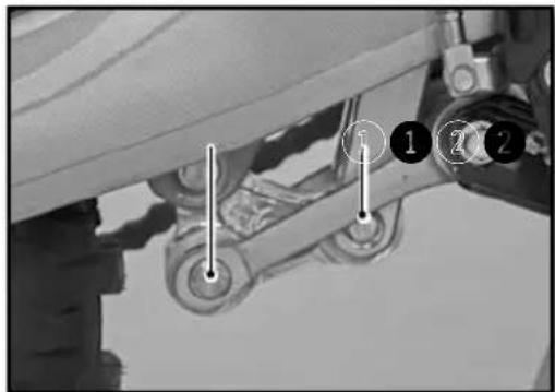
Position the rods and "H" link.
Install the lower shock screw 1 and tighten.
| Lower shock screw | M10 40Nm Loctite ^ 2701 |
Install the lower shock shaft ② and tighten.
| Lower shock shaft M12 40Nm |
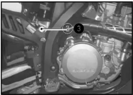
Reassemble the intermediate exhaust and install screw 3 loosely.
Reassemble the rear silencer and loosely tighten screws ④ using the nylock self-locking nuts.
| Chassis screws M6 10Nm |
Attach the intermediate pipe spring 5.
Attach the muffler spring 6.
Tighten the muffler attaching screws 4
| Chassis screws M6 10Nm |
Install right side plate.
Remove the bike from the stand.
Wheels, tires
REMOVING THE FRONT WHEEL

natural_image
Close-up of a bicycle wheel assembly with visible tracks and hub structure (no text or symbols)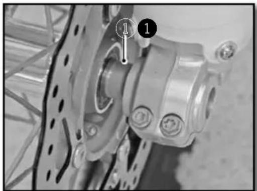
natural_image
Close-up of a bicycle wheel assembly with mounting holes and a numbered component (no visible text or symbols)
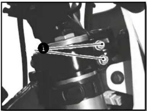
Place the motorcycle on a suitable stand.
Remove the two screws ① and the nut ②
Loosen the two screws 3
Pull the axle through the right side.
Remove the wheel from the fork.

WARNING
Do not operate the front brake lever when the front wheel is removed.
REINSTALLING THE FRONT WHEEL
Check that the brake disc is not dirty or contaminated with oil or grease. If it is, clean the disc with brake cleaner.
| Brake cleaner Motul | ® P2 Brake Clean |
Install the spacer ① on the left side of the wheel hub.
Install the front wheel in the fork and install the axle (grease the axle prior to installation).
Tighten the screws ②.
| Fork screws M8 12Nm |
Install and tighten the axle nut ③.
| Front axle nut M20 25Nm |
Tighten the screws on the right side of the bike.
| Fork screws M8 12Nm |
Operate the front brake lever several times until the pads touch the disc.Remove the bike from the stand and push down on the fork several times.
Wheels, tires (continued)
REMOVING THE REAR WHEEL
natural_image
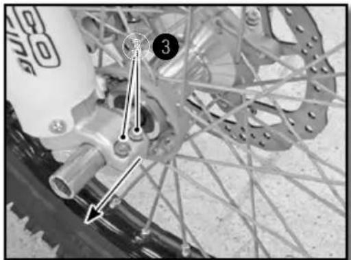
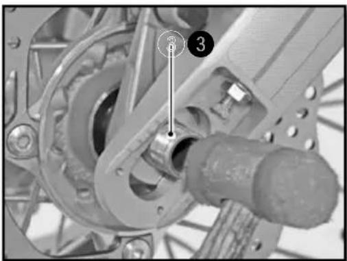
Mechanical assembly diagram showing a gear and shaft assembly with numbered components (no readable text or symbols)Place the motorcycle on a suitable stand.
- Unscrew the nut ^1 and remove the adjuster. ^2
- Tap the axle ③ out using a nylon hammer.
- Remove the axle.
- Move the wheel as far forward as possible.
- Remove the chain and wheel.

WARNING
Do not operate the rear brake pedal when the rear wheel is removed.
REINSTALLING THE REAR WHEEL
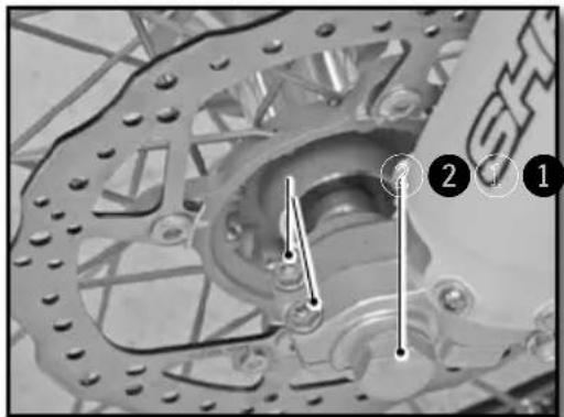
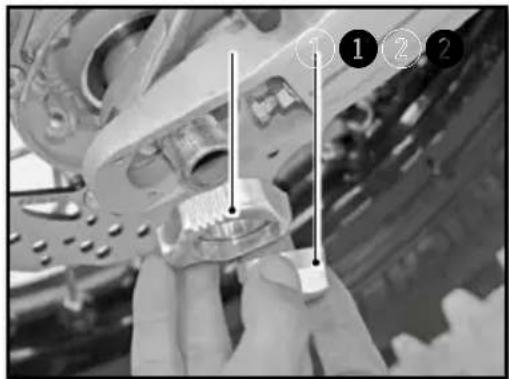
natural_image
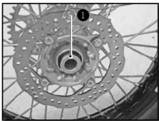
Close-up of a bicycle wheel assembly with gear and hub (no visible text or symbols)Check that the brake disc is not dirty or contaminated with oil or grease. If it is, clean the disc with brake cleaner.
| Brake cleaner Motul | ® P2 Brake Clean |

natural_image
Close-up of a bicycle wheel with gear and hub, showing mechanical components and a numbered annotation (no readable text or symbols)Install the two spacers ① and ② and make sure they are positioned correctly.
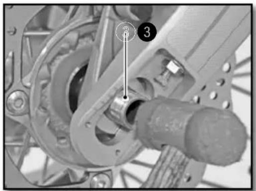
natural_image
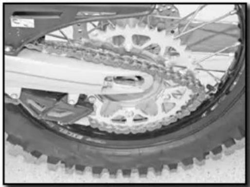
Close-up of a bicycle's wheel and gear assembly, showing teeth and chain (no text or symbols visible)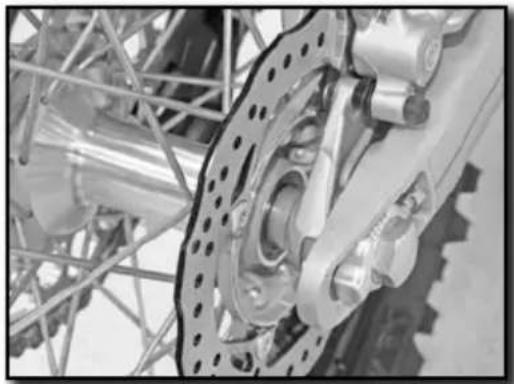
natural_image
Close-up of a mechanical assembly with gears and linkages (no visible text or symbols)Install the rear wheel in the swing arm and install the axle (grease the axle prior to installation) Mount the chain.
Install the chain tensioner ① and install the nut ② but do not tighten.
Check the chain tension (p.105)
Tighten the nut 2.
| Rear Axle nut M24 100Nm |
Operate the rear brake pedal several times until the pads touch the disk.
Remove the bike from the stand.
CHECKING THE TIRE PRESSURE
natural_image
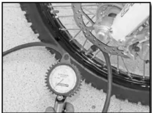
Close-up of a bicycle wheel with a pressure gauge and cable, no visible text or symbolsRegularly check the tire pressure with a precision pressure gauge.
- Remove the valve cap.
- Check air pressure when the tire is cold.
Tire air pressure when used in rough terrain.
| Front 0,9bar (13 psi) | |
| Rear 0,9bar (13 psi) |
If the pressure does not comply with the above table :
- Correct the pressure.
- Replace the valve cap.
Wheels, tires (continued)
CHECKING FOR WEAR AND DAMAGE
- Regularly check the depth of the tread.
Tread depth ≥3mm
If the depth is less than the value shown :
- Change the tire
Check for cuts, cracks, nails, sharp objects and bulges on the tire.
If the tire is damaged :
- Change the tire
CHECKING SPOKE TENSION
natural_image
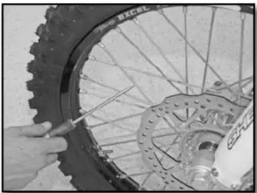
Close-up of hands using a tool to adjust the wheel rim and disc (no visible text or symbols)Do not neglect the tension of the spokes.
WARNING
Proper tension ensures stability and secure riding.
- Check the spoke tension before and after each use of the bike, especially if the spokes are new or have been recently adjusted.
- Use a screwdriver to tap on each spoke. The sound must be sharp.
- If it is dull, take the bike to a SHERCO dealer to get the spokes properly adjusted.
Note : indicative tightening torque of 5 to 6 Nm.
Brakes
natural_image
Mechanical component with labeled parts and directional arrow (no readable text or symbols)Pull the lever toward the handlebar and check the free play A
Free play of the front brake lever ≥3mm
If the free play does not meet the specification, do the following.
natural_image
Close-up of a bicycle brake lever with a numbered indicator (1) pointing to the handle (no text or symbols on the lever itself)Set the free play using the adjustment screw 1
- Turn clockwise to decrease the free play.
- Turn it counterclockwise to increase the free play.
natural_image
Close-up of a mechanical assembly with hoses and connectors (no visible text or symbols)Make sure that the reservoir is in a horizontal position.
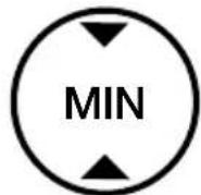
Check the fluid level through the sight glass. Ensure that the level is (between the arrows) it should be closest to the up arrow.
If the level is below the MIN mark, top up the brake fluid according to the instructions below.
- The hydraulic fluid is highly corrosive.
- It can be dangerous to the skin.
- Read the recommendations on the container.
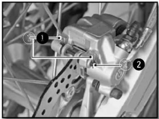
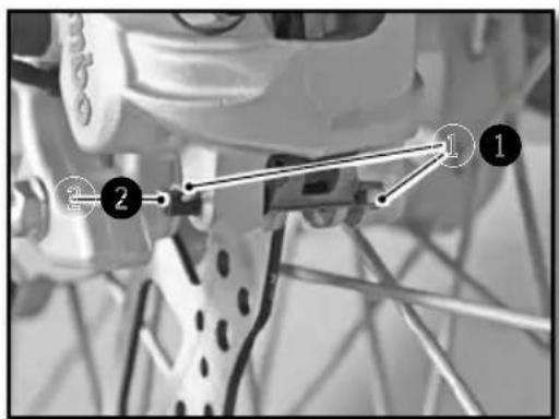
- Remove the two screws 1 .
Remove the cover 2 and the membrane 3.
Fill the reservoir with brake fluid to the correct level A.
| Level of brake fluid below the top of the reservoir. | 5mm |
| Motul® RBF 700 Brake fluid DOT 4 | |
- Reinstall the membrane, the cover and the screws.
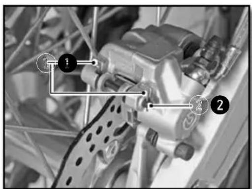
The position of the brake pedal can be adjusted as follows: loosen the lock nut 1 loosen or tighten the screw 2 to obtain the desired position.
Tighten the lock nut when the pedal is properly located.
| Brake pedal lock nut M6 10Nm |
Check the pedal travel (p.114)
CHECKING THE TRAVEL OF THE REAR BRAKE PEDAL
- Remove the spring 1
- Operate the pedal several times
| Rear brake pedal travel | 3mm ≥ A ≥5mm |
- Replace the spring 1
If the travel does not meet the specification, refer to the rear brake travel adjustment. (p.115)
ADJUSTING THE TRAVEL OF THE REAR BRAKE PEDAL
- Remove the spring 1
- Loosen the nut ^2 and turn the shaft ^3
| Rear brake pedal travel | 3mm ≥ A ≥5mm |
Hold the shaft ③ and tighten the nut ②.
| Nut 2 | M6 | 10Nm |
- Reinstall the spring 1
natural_image
Close-up of a mechanical assembly with visible springs and bolts (no text or symbols)Position the motorcycle on a flat surface.
Check the fluid level through the sight glass.
Ensure that the level (between the arrows) is closest to the up arrow.
If the level is below the MIN mark, top up the brake fluid according to the instructions below.
Remove the cap ① with its membrane ②.
Fill with fluid to the mark as shown A
Motul® RBF 700 Brake fluid DOT 4
- Reinstall the membrane and the cover using a new O-ring.
natural_image
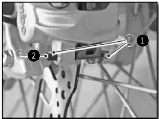
Close-up of a mechanical component with a labeled section 'A' (no readable text or symbols beyond label)REMOVING THE FRONT AND REAR BRAKE PADS

- Remove the clip ① and retaining pin ②.
- Remove the brake pads.
Do not operate the front brake lever or rear brake pedal when the brake pads are removed.
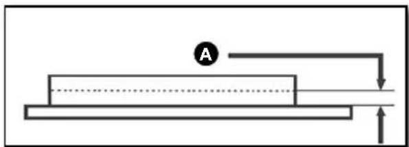
CHECKING THE CONDITION OF THE BRAKE PADS
natural_image
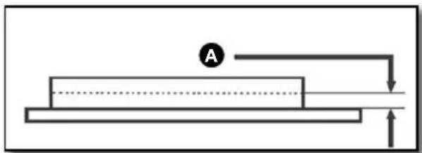
Simple line diagram of a mechanical setup with a block, a circular element labeled 'A', and directional arrows (no text or symbols)Check the pads for wear
Minimum pad thickness
A ≥1mm
If replacement is necessary, always change the pads in pairs.
REINSTALLING THE FRONT AND REAR BRAKE PADS
Check that the brake discs are not contaminated with oil or grease. In they are, clean the discs with brake cleaner.
Brake cleaner Motul
® P2 Brake Clean
Install the new pads.
Reinstall the retaining pins ② and clips ①
Check the brake fluid level and fill if necessary. (p.113 and p.114)
WARNING
Do not use the bike until the brake lever and the pedal are operational. «Pump» the brake lever / brake pedal up and down until the brake pads are in contact with the discs.
Electrical system maintenance
REMOVING THE BATTERY
Turn off all electric devices and stop the engine.
WARNING
Wait at least 30 secondes, bike turned off and stopped, so that the Keyless system turns off.
If this is not done there is a significant risk of damage to
- Remove the seat (p.99)
- Remove the air filter (p.99).
- The battery is located at the bottom of the filter housing.
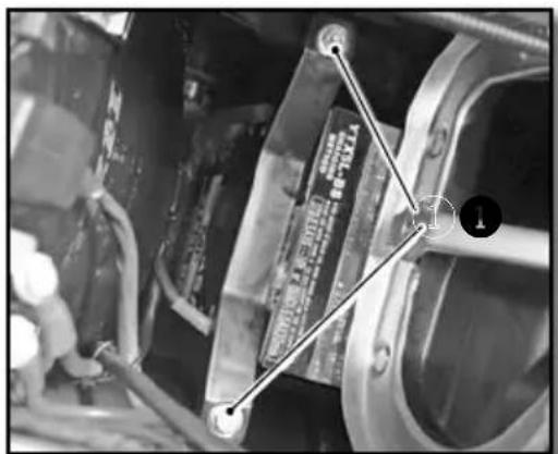
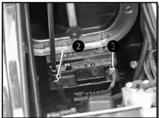
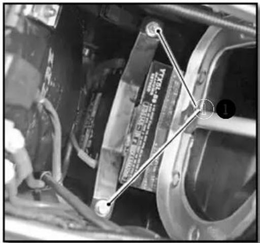
- Remove the two screws ^1 that retain the battery retaining bracket.
- Disconnect the negative cable from the battery ^2 .
- Disconnect the battery positive cable ③.
- Remove the battery from the top.
Electrical system maintenance (continued)
REINSTALLING THE BATTERY
CHARGING THE BATTERY
- Insert the battery into place.
- Connect the positive cable to the battery.
- Connect the negative cable to the battery.
- Install the battery retaining bracket and tighten the two screws ①.
Chassis screws M6 10Nm
- Check the positioning of the battery cables to make sure that they do not interfere with the installation of the air filter.
- Replace the air filter (p.100).
- Replace the saddle (p.99).
The battery is a maintenance-free type. If the vehicle is not used for an extended period, it is recommended that the battery be disconnected and stored in a dry place. See removing the battery (p.117)
Check the voltage of the battery with a voltmeter :
Battery voltage >12.5V
If the voltage is below the specification, remove the battery and recharge it using a battery charger.
Battery charging (12V) 0.5 A for 10 hours or 5A for 30 minutes
Disconnect the charger after charging.
Install the battery (p.118).
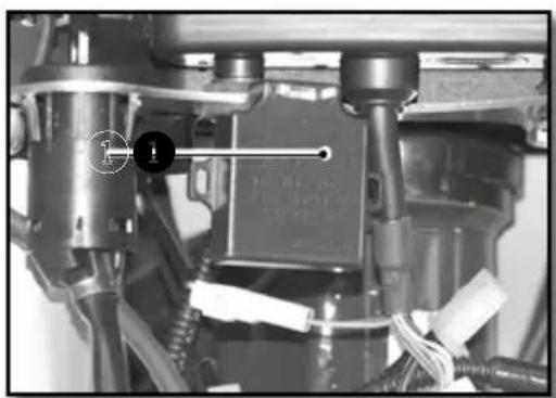
REPLACING THE MAIN FUSE
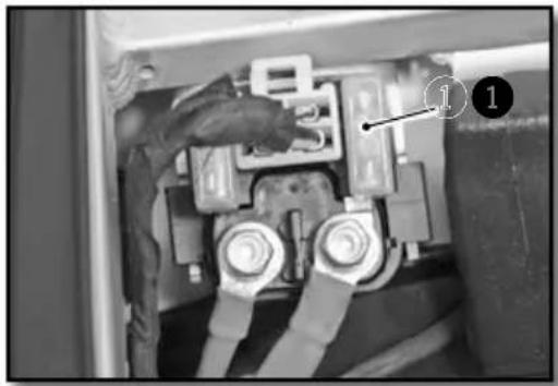
natural_image
Close-up of a mechanical component with labeled parts (1 and 2), showing wiring and housing connections without any readable text or symbols.Remove the seat (p.99)
The main fuse ① is on a relay by the starter.
Remove the defective fuse and replace with a new fuse of the same value.
Main fuse 30A
Put a new spare fuse in the reserve location in the fuse box.
- Replace the saddle (p.99).
REPLACING THE FUSE FOR THE LIGHTS
natural_image
Close-up of a mechanical component with wires and a labeled connection point (no readable text or symbols)Remove the seat (p.98)
The light fuse 1 is located in a high location on the wiring harness on the right side of the bike.
Remove the defective fuse and replace with a new fuse of the same value.
Light fuse 15A
- Replace the saddle (p.99).
REMOVING THE HEADLIGHT HOUSING
natural_image
Close-up of mechanical components with no visible text or symbolsTurn the ignition to the off position.
Unclip the left and right rubber fastners ① on each side of the fork.
Separate all of the brake hoses / cables from the meter bracket at the top and bottom.
Move the top plate up to clear the housing.
Disconnect the connector ② and remove theheadlight housing.
natural_image
Close-up of a mechanical assembly with no visible text or symbolsElectrical system maintenance (continued)
REINSTALLING THE HEADLIGHT HOUSING
Connect the electrical connector.
Engage the light plate, ensuring that the holes in the plate ① are in place ②.
Place all of the brake hoses / cables in the interior of meter upper guide ③.
Attach the rubber fastners.
Check the setting of headlight beam. (p.121)
REPLACING THE HEADLIGHT BULB OR THE PILOT LAMP
Remove the headlight housing assembly (p.119)
Remove the protective rubber 1
Turn the socket a quarter turn counterclockwise to remove it from the headlight assembly.
Gently press the bulb in while turning it counterclockwise and remove it from the socket.
Install a new bulb ②.
Headlight bulb S2 12V 35/35W S2
natural_image
Close-up of hands installing or adjusting a mechanical component with a tool, no visible text or symbolsReinstall the socket with the bulb in the headlight assembly by turning it in a clockwise direction.
Reinstall the protective rubber.
To replace the pilot light ③ simply remove the socket from the reflector ②.
Pilot light W5W 12V 5W
Reinstall the headlight housing assembly (p.120)
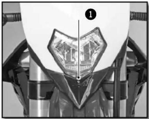
ADJUSTING THE HEADLIGHT BEAM
natural_image
Close-up of a mechanical component with a transparent eye-like structure and a numbered marker (1), no visible text or symbols.The headlight beam is adjusted with the motorcycle in a state of operation with its driver seated on the saddle.
To set the headlight beam, tighten or loosen the screw at the base of the headlight housing.
Tightening the screw ① raises the headlight beam.
Loosening the screw ① lowers the headlight beam.
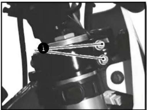
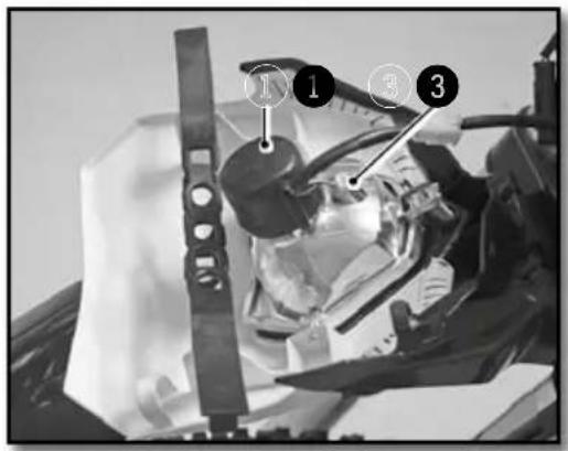
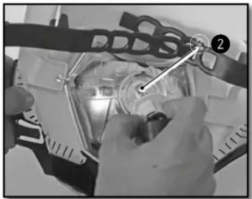
REPLACING THE MOTORCYCLE COMPUTER BATTERY
natural_image
Mechanical assembly with labeled components and wiring (no readable text or symbols)- Remove the headlight housing (p.119).
- Remove the turn ① signal flasher in order to access the motorcycle computer screws.
- Remove the screws ② and remove the computer to get it out of the way.
- Disconnect the main connector from the computer.
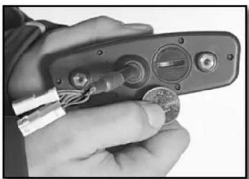
- Open the computer with a coin and remove the battery.
- Install a new battery (with the marking up).
Computer battery CR 2032 3V
natural_image
Close-up of mechanical components with numbered annotation (2) and no visible text or symbols- Replace the cover, taking care not to damage the O-ring.
- Plug the main connector into the computer.
- Install it on the bike and check to make sure the meter works.
- Reinstall the computer support.
- Install screws ^2 and replace the turn signal flasher.
- Replace the headlight housing (p.120)
- Set the computer (p.81)
natural_image
Close-up of a hand holding a handheld electronic device with wires and a coin, no visible text or symbolsWASHING THE BIKE STORING THE BIKE
SHERCO advises you to wash your Sherco as often as possible in order to maintain it in good working order and prolong its life.
- Cover the end of the exhaust silencer and the air filter (plastic bag, special cover or a special cap).
- To degrease the engine, apply a degreaser, clean with a brush then rinse the engine with a water hose.
- Wash the rest of the vehicle with hot soapy water.
- Rinse with clear water.
- Dry with a chamois or a clean, soft cloth.
- Clean the chain and lubricate it with a special chain lube.
- When the cleaning is finished, remove the air filter and exhaust protection, Start the engine and let it run atidle for a few minutes.
Avoid using high pressure equipment which may cause water to leak into the bearings and fork seals and cause serious damage. Use an average strength detergent rather than a strong detergent.

CAUTION
In order to avoid any water ingress, keep a minimal washing distance of 20cm.
Before storing the vehicle Long-Term (more than 2 months), follow these instructions :
- Wash the whole bike.
- Empty the fuel tank.
- Remove the spark plug and inject a protective spray inside the engine through the hole in the cylinder. Install the spark plug. Cycle the engine a few revolutions to apply a protective film on the cylinder walls.
- Remove the battery (p.117)
- Charge the battery (p.118)
- Lubricate all cables with a spray lubricant.
- Jack the motorcycle up so that the wheels are off the ground.
- Cover the exhaust outlet with a plastic bag to prevent moisture from entering.
- Spray a protective oil film on all unpainted metal surfaces of the motor and also on the electrical wiring.
- Cover the motorcycle with a cover.
RECOMMISSIONING AFTER STORAGE
Reinstall the battery (p.118)
Fill the fuel tank.
Perform lubrication and maintenance (p.123)
Perform a road test.
Maintenance schedule
| Maintenance | After 5 hours | Every 20 hours |
| ENGINE | ||
| Change engine oil, filter, clean pre filter and change if necessary | ● | ● |
| Clean the magnetic drain plug | ● | ● |
| Replace spark plug (after 50 hours) | ||
| Check and adjust valve clearances | ● | ● |
| Check engine mounting bolts for tightnessr | ● | ● |
| INJECTION | ||
| Clean the venturi | ● | |
| ACCESSORIES | ||
| Check cooling system for leaks | ● | ● |
| Check sealing and attachment of the exhaust | ● | ● |
| Check status, flexibility and position of the cables, adjust and lubricate | ● | ● |
| Check oil level in clutch master cylinder | ● | ● |
| Clean air filter and housing | ● | ● |
| Check status and position of the electrical wiring | ● | ● |
| Check function of electric components (headlight/tail/stop turn signals, computer control unit, etc.) | ● | ● |
| BRAKES | ||
| Check brake fluid level, brake pad thickness and the brake discs | ● | ● |
| Check status and sealing of the brake lines | ● | |
| Check status, of the foot brake pedal and hand brake lever | ● | ● |
| Check tightness of brake system fastners and discs | ● | ● |
| CHASSIS | ||
| Check for leaks and function of fork and shock | ● | ● |
| Clean the dust covers | ● | |
| Purge air from the fork legs | ● | |
| Check general tightness of bolts and screws | ● | |
| Check / adjust steering head bearings | ● | ● |
| WHEELS | ||
| Check rims and spoke tension | ● | ● |
| Check condition of the tires and tire pressure | ● | ● |
| Check chain, sprockets, guides, chain tension | ● | ● |
| Lubricate the chain | ● | ● |
| Check wheel bearing clearance | ● | ● |
Maintenance schedule (continued)
| ANNUAL MAINTENANCE | ||
| Major maintenance items that should be performed by the dealer | 1X by year minimum | |
| Fork | ● | |
| Shock | ● | |
| Clean and grease steering head bearings and seals | ● | |
| Treat electric contacts and switches with an aerosol protector | ● | |
| Replace the clutch hydraulic fluid | ● | |
| Replace the brake fluidn | ● | |
| Checks and major maintenance to be performed by the rider | Before each use | After each use |
| Check the engine oil level | ● | |
| Check brake fluid level | ● | |
| Check status of the brake pads | ● | |
| Verify operation of the lights | ● | |
| Verify operation of the horn | ● | |
| Lubricate throttle cable | ● | |
| Regularly purge the air from the fork legs | ● | |
| Regularly clean the fork dust seals | ● | |
| Clean and lubricate chain, check tension and adjust if necessary | ● | |
| Clean air filter and box | ● | |
| Check tires and tire pressure | ● | |
| Check the coolant level | ● | |
| Check fuel lines for leaks | ● | |
| Check status of all the controls | ● | |
| Check the brakes | ● | ● |
| Spray anti-corrosion protector on all non painted parts (except for the brake parts and the exhaust system) | ● | |
| Spray protector on electrical switches | ● | |
| Check tightness of nuts, screws and clamps | ● | |

WARNING
Check the tightening of the screws of your bike after the first ride / the first hours of use.
In competition you have to perform the 20 hour maintenance schedule after each race!
This should not be exceeded by more than 2 hours.
The services performed by the Sherco dealer do not replace routine service and maintenance by the rider!
IMPORTANT CHECKS AND MAJOR MAINTENANCE ITEMS THAT SHOULD BE PERFORMED BY THE SHERCO DEALER
| Competition use | At 20H At | 50H At 100H | |
| Recreational user | At 50H At | 100H | |
| Check the clutch disc wear | ● ● ● | ||
| Check the length of the clutch springs | ● ● ● | ||
| Check that the clutch nut is not loose | ● | ● | |
| Check that the clutch housing is not loose | ● | ● | |
| Check the wear of the cylinder and piston | ● | ● | |
| Replace the piston | ● | ● | |
| Check the camshafts for wear (a) visually check | ● | ● | |
| Check the camshaft buckets for wear | ● | ● | |
| Check the wear of valve guides | ● | ● | |
| Replace the valves | ● | ||
| Replace the valve springs | ● | ||
| Check operation of chain tensioner guide | ● | ● | |
| Check the run-out at the end of the crankshaft | ● | ● | |
| Check the condition of the connecting rod | ● | ● | |
| Replace the big end bearing | ● ● ● | ||
| Replace the crankshaft bearings | ● | ● | |
| Check all of the gearbox components for wear | ● | ● | |
| Check ECU's errors with the Sherco diagnostic tool | ● ● ● | ||
| Check and charge the battery | ● ● ● | ||
| Check the fuel pressure | ● ● ● | ||
| Check the oil pump | ● ● ● | ||
| Check the length of the relief valve spring | ● | ● | |
| Replace fiberglass packing in the muffler | ● ● ● | ||
| Check the length of the camshaft drive chain | ● | ● | |
| Check the camshaft bearings | ● |
Torques
ENGINE TIGHTENING TORQUES
| Magnetic Drain Plug M12 15Nm | ||
| Prefilter drain plug M18 15Nm | ||
| Oil filter cap M45 15Nm | ||
| Sparkplug (apply grease to the copper washer) 15Nm | ||
| Water pump housing screws M6X8 6Nm | ||
| Radiator bleed screw M6X8 8Nm | ||
| Drain plug with large pre-filter M32 20Nm |
CHASSIS TIGHTENING TORQUES
| Shock screw lock nut M5 5Nm | |||
| Other chassis screws M6 10Nm | |||
| Other chassis screws M8 24Nm | |||
| Disc brake screws front / rear M8 24Nm Loctite | ^® 243 ^TM | ||
| Crown screw M8 23Nm | |||
| Handlebar clamp fastening screws | M8 25Nm | ||
| Fork upper screw | M8 17Nm | ||
| Fork lower screw | M8 15Nm | ||
| Upper screw | M8 17Nm | ||
| Fork pinch bolt screw M8 12Nm | |||
| Side support screw | M8 25Nm Loctite | ^® 243 ^TM | |
| Other chassis screws | M10 | 40Nm | |
| Handlebar fixing screws | M10 | 40Nm Loctite | ^® 243 ^TM |
| Top shock screw | M10 | 40Nm | Loctite ^® 2701 |
| Lower shock screws | M10 | 40Nm | Loctite ^® 2701 |
| Motor mounting bolts M10 40Nm | |||
| Suspension delta / H link bolts | M12 | 40Nm | |
| Swing arm pivot bolt | M16 | 100Nm | |
| Front wheel nut M20 25Nm | |||
| Steering shaft nut | M20 | 30Nm | |
| Rear wheel nut | M24 | 100Nm | |
The image contains only dotted lines, which are stylistic or background elements and not text. According to the correction guidelines, such lines must be ignored. Therefore, the correct OCR output is empty.
(no text)
INDEX
SHERCO
FRANÇAIS P.4
■ ENGLISH P.66
■ ESPAÑOL P. 130
DEUTSCH P. 194
INTRODUCCIÓN
SHERCO
natural_image
Empty rectangular frame with black border (no text or symbols)natural_image
Empty rectangular frame with rounded corners (no text or symbols)■ Lado derecho
① Intermitentes traseros
② Sillín
3 Pedal de freno trasero
4 Depósito
5 Intermitentes delanteros
6 Faro

■ Lado izquierdo
natural_image
Close-up of an internal mechanical assembly with gears and springs (no visible text or symbols)■ Interruptor luz on/off
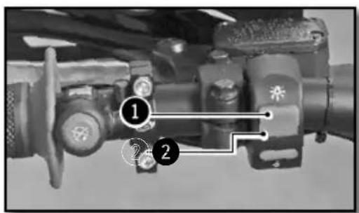
natural_image
Close-up of a mechanical knob or dial with a circular handle, no visible text or symbols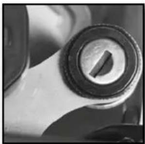
natural_image
Close-up of a mechanical knob or dial component (no visible text or symbols)natural_image
Close-up of a mechanical assembly with labeled parts (no readable text or symbols)natural_image
Close-up of a mechanical switch component with no visible text or symbols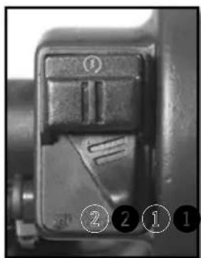
natural_image
Close-up of a mechanical component with no visible text or symbols① Mando de Freno trasero
Caballete lateral

natural_image
Mechanical assembly showing a worker adjusting a vehicle chassis with a ladder and numbered component (no visible text or symbols)Fig 2 Función MAX
Fig 8 Función ART
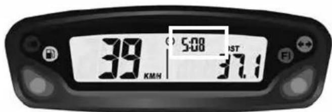
Fig 9 Función Hora
natural_image
Close-up of a motorcycle's front wheel and suspension components (no visible text or symbols)natural_image
Close-up of a robotic arm gripping a small object, possibly a sensor or device, with no visible text or symbols.natural_image
Close-up of a mechanical assembly with labeled parts (1 and 2), no readable text or symbols present.
natural_image
Close-up of hands adjusting a mechanical component with a circular housing (no visible text or symbols)
natural_image
Two identical cylindrical objects with vertical stripes, one emitting a droplet (no text or symbols)Moto horizontal

ATENCIÓN
natural_image
Close-up of a mechanical assembly with visible gears and springs (no text or symbols)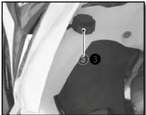
natural_image
Top-down view of a motorcycle's head and front wheel assembly (no visible text or symbols)
ATENCIÓN
natural_image
Close-up of a bicycle brake lever with a curved arrow indicating rotational motion (no text or symbols visible)natural_image
Close-up of a motorcycle's brake lever and grip mechanism (no text or symbols visible)natural_image
Close-up of a mechanical component with a hand adjusting parts, no visible text or symbolsnatural_image
Close-up of hands operating a mechanical component with a circular dial (no visible text or symbols)Rellenar de aceite de motor
Aceite motor SAE 10w60

ATTENTION
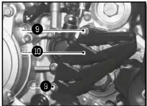
natural_image
Close-up of mechanical components including gears and springs, no visible text or symbolsnatural_image
Close-up of mechanical components with no visible text or symbolsnatural_image
Close-up of mechanical components with no visible text or symbols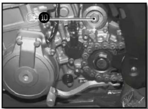
natural_image
Close-up of mechanical components with no visible text or symbols

natural_image
Technical drawing of a mechanical component with cross-sectional hatching and dimension line (no text or symbols)
WP

natural_image
Close-up of a motorcycle's front wheel and side-mounted sensors (no visible text or symbols)KAYABA
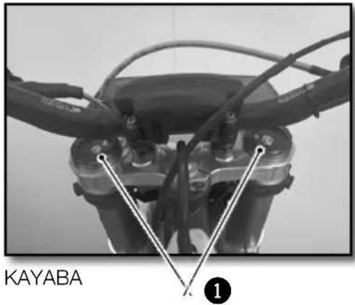
natural_image
Close-up of a mechanical tool with a metallic clamp and threaded shaft (no visible text or symbols)WP
KAYABA
AMORTIGUADOR WP (RACING)
natural_image
Close-up of a mechanical component with two numbered parts (1 and 2) showing internal features and alignment, no readable text or symbols present.WP
natural_image
Close-up of a white SHERO KARX motorcycle with visible branding and mechanical components (no readable text beyond branding)KAYABA
AMORTIGUADOR WP (RACING)
natural_image
Close-up of mechanical components with no visible text or symbolsnatural_image
Interior view of a vehicle showing a large spherical object and surrounding compartments (no visible text or symbols)natural_image
Close-up of a mechanical component with visible internal blades and a numbered annotation (2) pointing to a specific part.natural_image
Top-down view of a mechanical component with multiple rods radiating from a central hub, labeled with numbers 1 and 2 (no text or symbols on the diagram itself)natural_image
Interior view of a vehicle showing a spherical object and mechanical components (no visible text or symbols)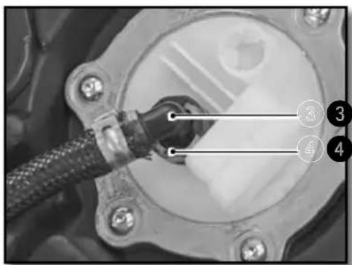
natural_image
Close-up of a mechanical component with a connector inserted, labeled with numbers 3 and 4 (no readable text or symbols beyond labels)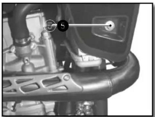
natural_image
Close-up of a mechanical component with labeled parts (no readable text or symbols)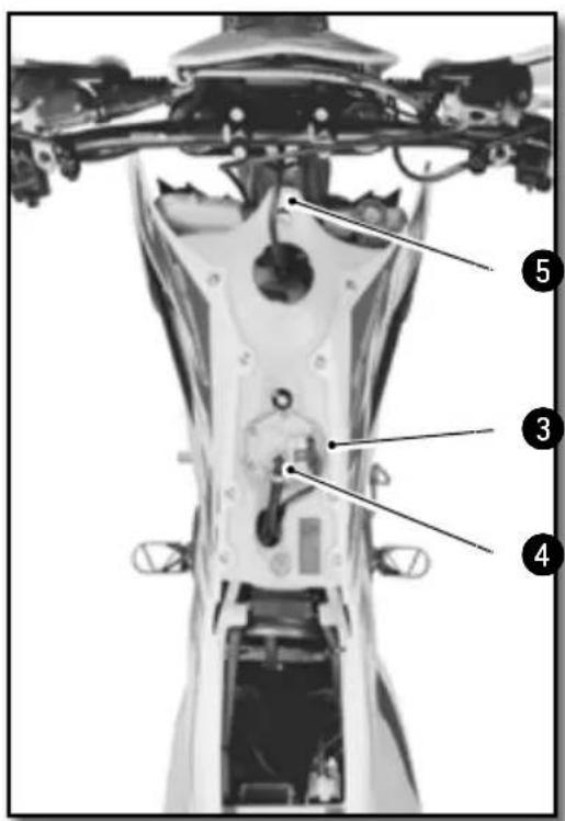
natural_image
Close-up of metallic cylindrical mechanical components with black connectors (no visible text or symbols)Moto sobre trípode.
natural_image
Side view of a modified off-road motorcycle with visible dynamics arrows indicating motion (no text or symbols)Moto sobre trípode.
Moto sobre trípode.
natural_image
Close-up of mechanical components with a numbered connection point (1) and connecting rods, no visible text or symbols.| Tornillo de platina inferior | M8x35 15Nm |
Apretar el tornillo 2
| Tornillo de te superior | M8x30 | 17Nm | Loctite®243TM |
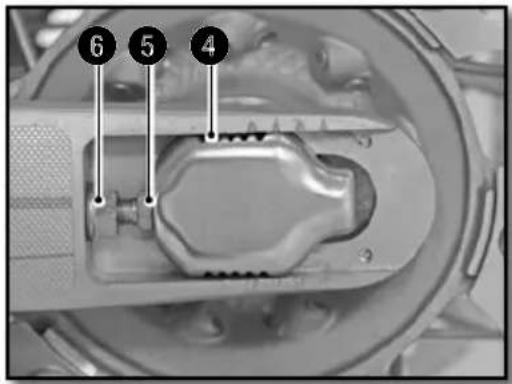

natural_image
Close-up mechanical assembly showing a component with a numbered marker (7) and a vertical line, no readable text or symbols present.REGLAJE EMBRAGUE

natural_image
Close-up of a motorcycle's grip and lever mechanism (no text or symbols visible)
ATENCIÓN

ATENCIÓN
natural_image
Close-up of a mechanical assembly with numbered annotations (1 and 2) pointing to components, no readable text or symbols present.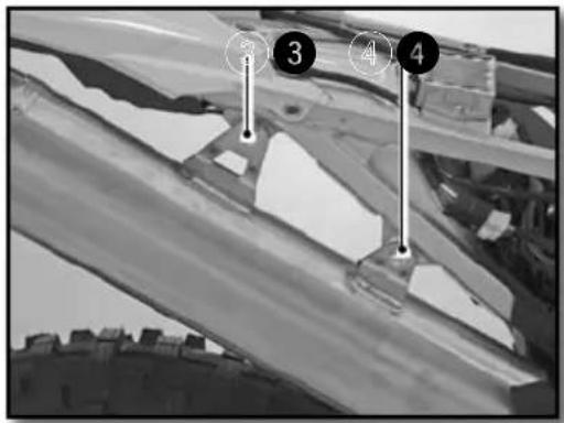


natural_image
Close-up of a mechanical assembly with springs and wiring (no visible text or symbols)Moto sobre trípode.
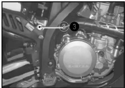
natural_image
Close-up of a mechanical assembly with numbered components (3) and no visible text or symbols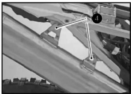
natural_image
Black-and-white photo of a mechanical component with numbered points (4 and 3) and no visible text or symbols
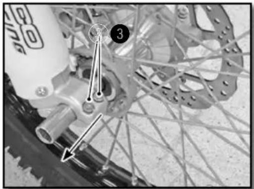
natural_image
Close-up of a bicycle wheel assembly with visible tracks and hub structure (no text or symbols)
natural_image
Close-up of a bicycle wheel assembly with mounting holes and a numbered component (no visible text or symbols)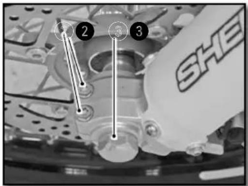
Moto sobre trípode.
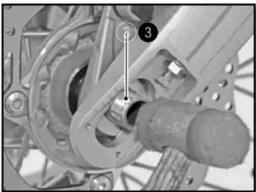
natural_image
Mechanical assembly diagram showing a gear and shaft assembly with numbered components (no readable text or symbols)Instalar la moto sobre un trípode.
natural_image
Close-up of a bicycle wheel assembly with visible gears and hub (no text or symbols)natural_image
Close-up of a bicycle wheel with gear and hub, showing mechanical components and a numbered arrow pointing to component 4 (no text or symbols beyond labels)natural_image
Close-up of a bicycle's wheel and gear assembly, showing teeth and chain (no text or symbols visible)natural_image
Close-up of a bicycle wheel with a pressure gauge and cable, no visible text or symbolsnatural_image
Close-up of hands using a tool to adjust the wheel rim and disc (no visible text or symbols)natural_image
Mechanical assembly diagram showing a lever and shaft assembly (no text or symbols visible)natural_image
Close-up of a mechanical component with a numbered annotation (1) pointing to a specific part, no readable text or symbols present.natural_image
Close-up of a mechanical assembly with hoses and connectors (no visible text or symbols)
ATENCIÓN
natural_image
Close-up of a mechanical assembly with visible springs and bolts (no text or symbols)natural_image
Close-up of a mechanical component with a labeled section 'A' (no readable text or symbols beyond label)natural_image
Simple line diagram of a rectangular block with an arrow indicating upward motion and a circular symbol labeled 'A' at the top (no text or symbols on the object itself)natural_image
Close-up of mechanical components with no visible text or symbolsCARGA DE LA BATERÍA
natural_image
Close-up of a mechanical component with labeled parts (1 and 2), showing internal wiring and housing (no readable text or symbols)natural_image
Close-up of a connector with wires and a numbered marker (1) pointing to a component, no readable text or symbols present.natural_image
Close-up of mechanical components with no visible text or symbolsnatural_image
Close-up of mechanical components with a numbered annotation (2) pointing to a specific part, no readable text or symbols present.natural_image
Close-up of hands assembling a mechanical component with a tool, no visible text or symbolsnatural_image
Close-up of a mechanical component with a transparent diamond-shaped opening and metallic components (no visible text or symbols)natural_image
Close-up of mechanical components with wires and a labeled pin (no readable text or symbols)natural_image
Close-up of mechanical components with numbered annotation (2) and connecting lines, no readable text or symbols beyond annotationsnatural_image
Close-up of a hand holding a handheld electronic device with wires and a coin, no visible text or symbols.LIMPIEZA DE LA MOTO ALMACENAMIENTO DE LA
MOTO
■ Rechte Seite
natural_image
Close-up of an internal mechanical assembly with gears and springs (no visible text or symbols)natural_image
Close-up of a mechanical component with two circular features, one showing a central hole and the other a segmented hole (no text or symbols visible)natural_image
Close-up of a mechanical assembly with numbered components (1 and 2), no visible text or symbols beyond labelsnatural_image
Close-up of a mechanical switch or lever mechanism (no visible text or symbols)
natural_image
Close-up of a mechanical component with no visible text or symbolsnatural_image
Close-up of a person's legs and chain track in a vehicle, with no visible text or symbolsnatural_image
Close-up of a motorcycle's front wheel and suspension components (no visible text or symbols)natural_image
Close-up of a robotic arm gripping a small object, possibly a sensor or device, with no visible text or symbols.natural_image
Close-up of a mechanical component with labeled parts (1 and 2), no readable text or symbols present.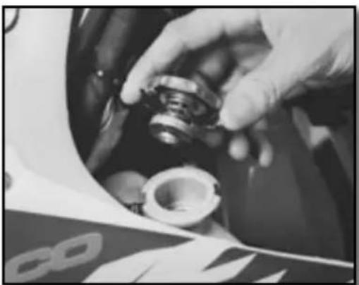
natural_image
Close-up of a hand adjusting a mechanical component, possibly a tire or bearing, with no visible text or symbols.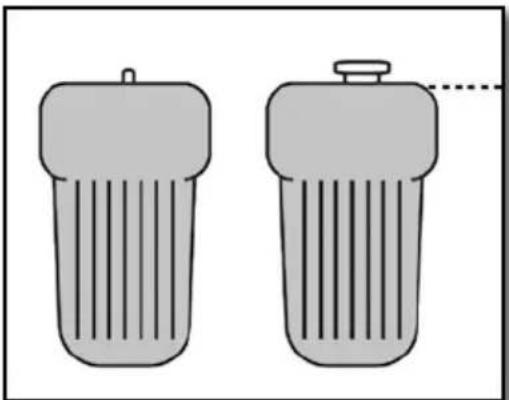
natural_image
Two identical cylindrical objects with vertical stripes, one emitting a droplet (no text or symbols)Motorrad horizontal

ACHTUNG
natural_image
Close-up of a mechanical assembly with visible gears and springs (no text or symbols)


ACHTUNG
natural_image
Close-up of a bicycle brake lever with a curved arrow indicating rotational motion (no text or symbols visible)natural_image
Close-up of a motorcycle's brake lever and grip (no visible text or symbols)natural_image
Close-up of a mechanical assembly with labeled parts (1) and 'SHE' logo, no readable text or symbols beyond the label.natural_image
Close-up of a mechanical component with a hand adjusting parts, no visible text or symbolsnatural_image
Simple hand-drawn circle with a downward arrow and two horizontal dashed lines inside, no text or symbols present.
natural_image
Close-up of hands operating a car engine component with a circular dial (no visible text or symbols)Motoröl nachfüllen
Motoröl SAE 10W40

ACHTUNG

natural_image
Close-up of a mechanical assembly with gears and shafts (no visible text or symbols)natural_image
Close-up of mechanical components with no visible text or symbolsMOTORÖL EINFÜLLEN
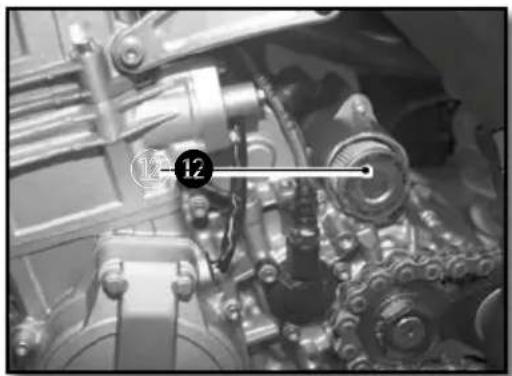
natural_image
Close-up of mechanical components with no visible text or symbols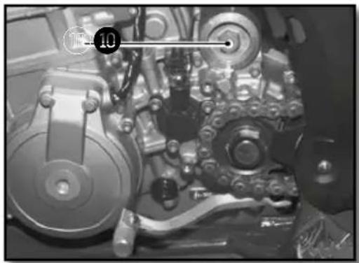
natural_image
Close-up of a mechanical assembly with gears and shafts (no visible text or symbols)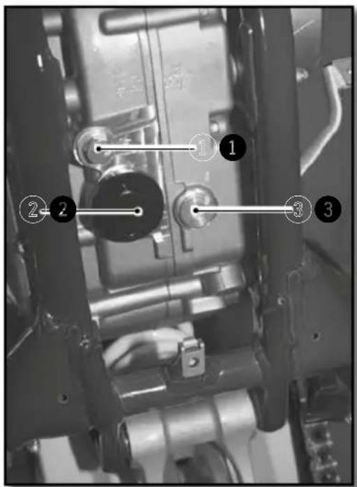

natural_image
Technical drawing of a mechanical component with cross-sectional hatching and dimension line (no text or symbols)
WP
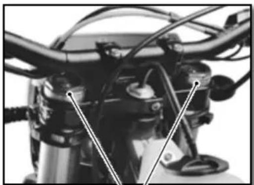
natural_image
Close-up of a motorcycle's front wheel and side brackets (no visible text or symbols)KAYABA
1
natural_image
Close-up of a motorcycle engine compartment with hoses and calipers (no visible text or symbols)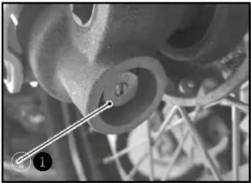
natural_image
Close-up of mechanical components with no visible text or symbolsnatural_image
Close-up of a mechanical wrench tool interacting with a vehicle (no visible text or symbols)WP
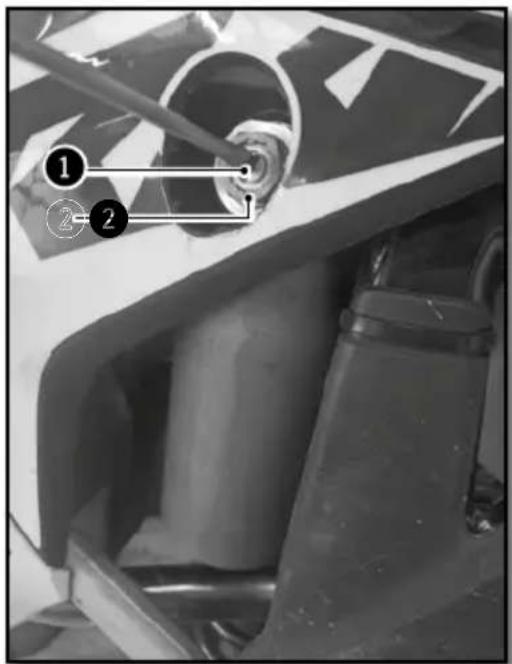
KAYABA
natural_image
Mechanical assembly diagram showing a shaft and housing with numbered annotations (1, 2, 3) indicating specific components or parts.WP
natural_image
Close-up of a white racing motorcycle's front wheel and suspension components (no visible text or symbols)KAYABA
STOSSDÄMPFER WP (RACING)
natural_image
Close-up of mechanical components with no visible text or symbolsnatural_image
Close-up of a mechanical component with visible internal blades and a numbered annotation (no text or symbols)natural_image
Top-down view of a mechanical component with multiple rods and a central hub (no text or symbols)natural_image
Interior view of a vehicle showing a large spherical object and surrounding equipment (no visible text or symbols)
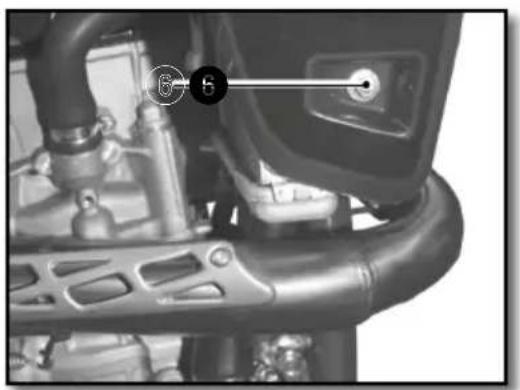
natural_image
Close-up of a mechanical component with labeled parts (no readable text or symbols)
natural_image
Close-up of metallic mechanical components with black connectors (no visible text or symbols)natural_image
Side view of a modified off-road motorcycle with visible dynamics arrows indicating motion (no text or symbols)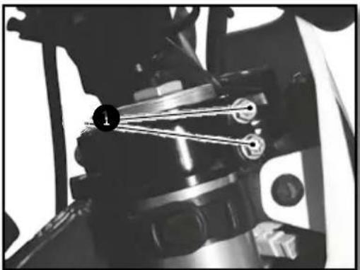
natural_image
Close-up of mechanical components with no visible text or symbols

natural_image
Close-up mechanical assembly showing a component with a numbered marker (7) and a vertical line, no readable text or symbols present.! ACHTUNG
natural_image
Close-up of a motorcycle's grip and lever mechanism, labeled with 'B' (no text or symbols on the diagram itself)
ACHTUNG
natural_image
Close-up of a mechanical assembly with numbered annotations (1 and 2) pointing to components, no readable text or symbols present.
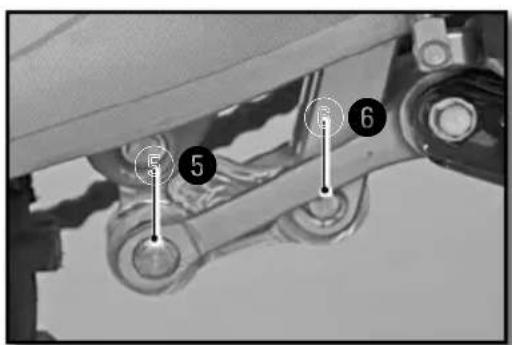

natural_image
Close-up of a mechanical assembly with springs and wiring (no visible text or symbols)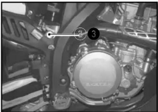
natural_image
Close-up of a mechanical assembly with numbered components (3) and no visible text or symbols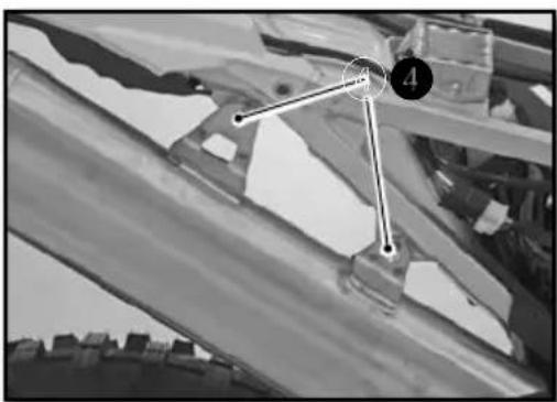
natural_image
Black-and-white photo of a mechanical or architectural component with numbered points (4 and 3) and no visible text or symbols.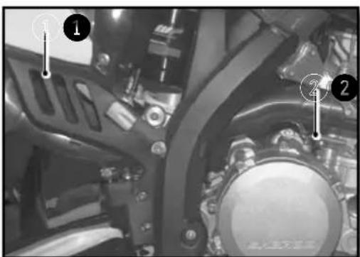
natural_image
Mechanical assembly diagram showing a gear-like component with numbered callouts (1, 2) and no readable text or symbols.
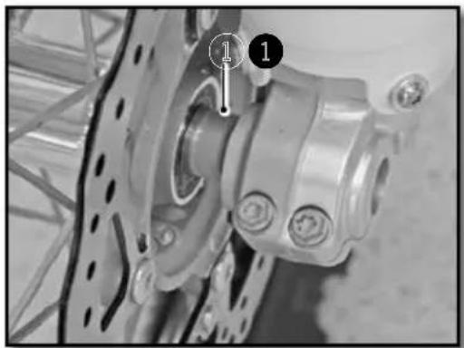
natural_image
Close-up of a bicycle wheel assembly with mounting holes and a numbered component (no visible text or symbols)

natural_image
Mechanical assembly diagram showing a gear and shaft assembly with numbered components (no readable text or symbols)natural_image
Close-up of a bicycle wheel assembly with gear and hub (no visible text or symbols)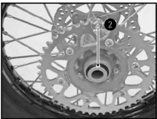
natural_image
Close-up of a bicycle wheel with gear teeth and a numbered component (no text or symbols visible)natural_image
Close-up of a bicycle's wheel and gear assembly, showing teeth and chain (no text or symbols visible)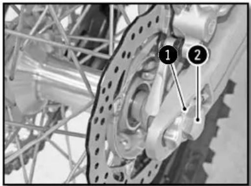
natural_image
Close-up of a bicycle wheel with a pressure gauge and cable, no visible text or symbolsnatural_image
Close-up of hands using a screwdriver to adjust the wheel rim and disc (no visible text or symbols)natural_image
Mechanical component with labeled parts and directional arrow (no readable text or symbols)natural_image
Close-up of a bicycle brake lever with a hand and belt, no visible text or symbolsnatural_image
Close-up of a mechanical assembly with hoses and connectors (no visible text or symbols)
ACHTUNG
natural_image
Close-up of a mechanical suspension system with visible springs and components (no text or symbols)natural_image
Close-up of a mechanical component with a labeled section 'A' (no readable text or symbols beyond label)KONTROLLE DER BREMSBELÄGE VORN UND HINTEN

natural_image
Simple line diagram of a mechanical setup with a block, a circular component labeled 'A', and an upward arrow (no text or symbols)LADEN DER BATTERIE
natural_image
Close-up of a mechanical component with labeled parts (1 and 2), showing wiring and connectors without any readable text or symbols.natural_image
Close-up of a connector with wires and a numbered marker (1) pointing to a component, no readable text or symbols present.natural_image
Close-up of mechanical components with no visible text or symbolsnatural_image
Close-up of mechanical components with a numbered annotation (2) pointing to a component, no readable text or symbols present.natural_image
Close-up of hands installing or adjusting a mechanical component with a tool (no visible text or symbols)natural_image
Close-up of a mechanical component with a transparent eye-like structure and a numbered marker (1), no visible text or symbols.natural_image
Mechanical assembly with labeled components and wiring (no readable text or symbols)natural_image
Close-up of a hand holding a handheld electronic device with wires and a coin, no visible text or symbolsnatural_image
Side view of a black and white DHTM 150 motorcycle with visible tracks, tires, and gear (no text or symbols)SHERCO recommends
MOTUL

MOTUL
KENNY
©Polisport

MICHELIN
UNIRACING
KYB
GROVE


GALFER

SCOTT