
PBTS 370 A1 - Sander PARKSIDE - Free user manual and instructions
Find the device manual for free PBTS 370 A1 PARKSIDE in PDF.
| Product type | Combined belt and disc sander |
| Brand | Parkside |
| Model | PBTS 370 A1 |
| Power consumption | 370 W |
| Power supply | 230-240 V ~ 50 Hz |
| Dimensions (L x W x H) | 460 x 360 x 280 mm |
| Weight | Approx. 16 kg |
| Disc diameter | 150 mm |
| Disc speed | 2980 min⁻¹ |
| Abrasive belt dimensions | 915 x 100 mm |
| Belt speed | 7.5 m/s |
| Belt tilt | 0° to 90° |
| Table tilt | 0° to 45° |
| Sound pressure level (idle) | 80.4 dB(A) |
| Sound power level (idle) | 88.7 dB(A) |
| Required personal protection | Safety glasses, hearing protection, dust mask |
| Use | Sanding wood and similar materials (indoor only) |
| Delivery contents | Sander, cross stop, sanding table, abrasive belt P80, abrasive disc P80, hex key, instruction manual |
| Wear parts | Abrasive belt, abrasive disc, timing belt |
| Extraction device | Extraction connection (except for metals) |
| Warranty | 3 years (excluding professional use) |
| Maintenance | Regular cleaning, monthly oiling of moving parts |
Frequently Asked Questions - PBTS 370 A1 PARKSIDE
User questions about PBTS 370 A1 PARKSIDE
0 question about this device. Answer the ones you know or ask your own.
Ask a new question about this device
Download the instructions for your Sander in PDF format for free! Find your manual PBTS 370 A1 - PARKSIDE and take your electronic device back in hand. On this page are published all the documents necessary for the use of your device. PBTS 370 A1 by PARKSIDE.
USER MANUAL PBTS 370 A1 PARKSIDE

BAND- UND TELLERSCHLEIFER PBTS 370 A1 BELT & DISC.SANDER PBTS 370 A1 PONCEUSE À BANDE/DISQUES PBTS 370 A1
DE ○ CHAT
Operating and Safety Instructions Translation of Original Operating Manual
NL BE
BAND- EN SCHIJFSCHUURMACHINES
Before reading, unfold the page containing the illustrations and familiarise yourself with all functions of the device.
FR BE
GB / IE Operating and Safety Instructions Page 12
Inhalt:
Seite:
Günzburger Straße 69
D-89335 Ichenhausen
Verehrter Kunde,
service.AT@scheppach.com
service.CH@scheppach.com
Service Adresse (DE): Service Adresse (AT):
Table of contents: Page:
- Explanation of the symbols on the device....13
- Introduction....14
- Device description (fig. 1-19)....14
- Scope of delivery....14
- Proper use....14
- Safety information....15
- Technical data....16
- Before commissioning....17
- Attachment and operation....17
- Transport....18
- Working instructions....18
- Cleaning and maintenance....19
- Storage....19
- Electrical connection....19
- Disposal and recycling 20
- Troubleshooting....20
- Warranty certificate....21
- Declaration of conformity....76
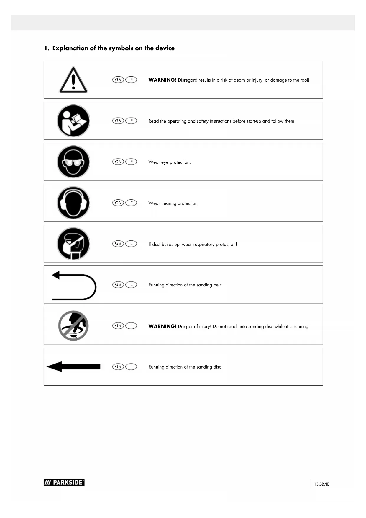
1. Explanation of the symbols on the device

GB IE
WARNING! Disregard results in a risk of death or injury, or damage to the tool!

GB IE
Read the operating and safety instructions before start-up and follow them!

GB IE
Wear eye protection.

GB IE
Wear hearing protection.

GB IE
If dust builds up, wear respiratory protection!

GB IE
Running direction of the sanding belt

GB IE
WARNING! Danger of injury! Do not reach into sanding disc while it is running!

GB IE
Running direction of the sanding disc
2. Introduction
Manufacturer:
scheppach
Günzburger Straße 69
D-89335 Ichenhausen
Dear Customer,
We hope your new tool brings you much enjoyment and success.
Note:
In accordance with the applicable product liability laws, the manufacturer of this device assumes no liability for damage to the device or caused by the device arising from:
- Improper handling,
• Non-compliance of the operating instructions,
• Repairs carried out by third parties, unauthorised specialists.
• Installing and replacing non-original spare parts,
• Application other than specified,
- Failure of the electrical system in the event of the electrical regulations and VDE provisions 0100, DIN 13 / VDE0113 not being observed.
Please consider:
Read through the complete text in the operating manual before installing and commissioning the device.
The operating manual is intended to help the user to become familiar with the machine and take advantage of its application possibilities in accordance with the recommendations.
The operating manual contains important information on how to operate the product safely, professionally and economically. This helps you to avoid danger, costly repairs, reduce downtimes and to increase reliability and service life of the machine. In addition to the safety instructions in this operating manual, you must also observe the regulations applicable to the operation of the machine in your country.
Keep the operating manual package with the machine at all times and store it in a plastic cover to protect it from dirt and moisture. They must be read and carefully observed by all operating personnel before starting the work.
The machine may only be used by personnel who have been trained to use it and who have been instructed with respect to the associated hazards. The required minimum age must be observed.
In addition to the safety instructions and the separate regulations of your country, the generally recognised technical rules for operating machines of the same type must also be observed.
We accept no liability for accidents or damage that occur due to a failure to observe this manual and the safety instructions.
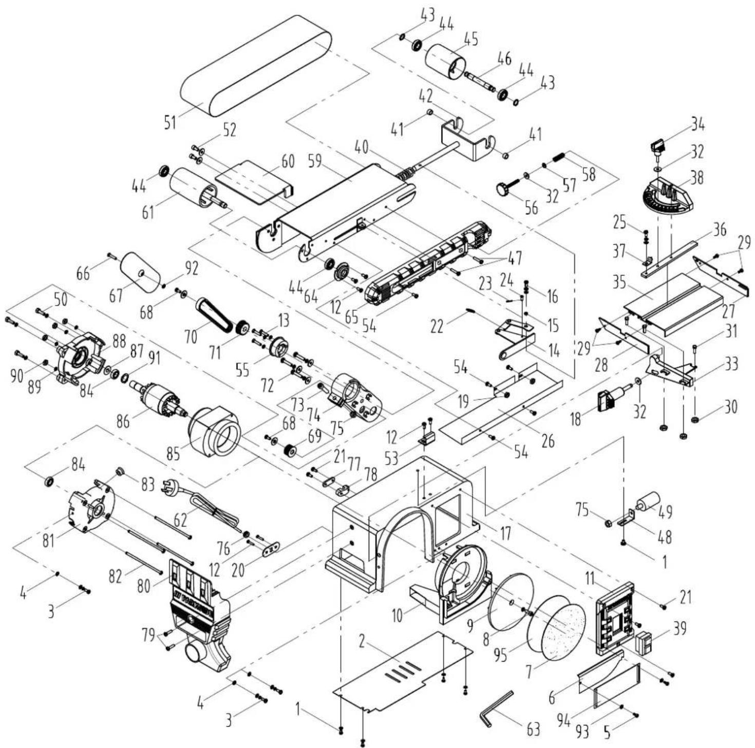
3. Device description (fig. 1-19)
1 Knurled screw for sanding belt adjustment
2 Support foot
3 Sanding belt tensioner
4 Sanding disc
5 On/off switch
6 Transverse stop
7 Sanding table
8 Locking screw for sanding table
9 Angle scale
10 Suction port
11 Base plate
12 Allen screw
13 Sanding belt
14 Stop rail
15 Bottom disc guard
16 Screw for bottom disc guard
17 Allen screw
18 Screw for sanding belt guard
19 Sanding belt guard
20 Holder tube
4. Scope of delivery
• 1 belt and disc sander
- 1 transverse stop
- 1 sanding table
• 1 sanding belt P80 (pre-assembled)
• 1 sanding disc P80 (pre-assembled)
• 1 Allen key
- 1 operating manual
5. Proper use
The purpose of the belt and disc sander is to sand all types of wood, depending on the size of the machine.
The machine complies with the applicable EC machinery directive.
- The manufacturer's safety, operating and maintenance specifications as well as the dimensions given in the technical data must be observed.
- Relevant accident prevention regulations and other generally recognized safety and technical rules must also be observed.
- The machine may only be used, maintained or repaired by trained persons who are familiar with it and have been informed of the dangers. Any liability of the manufacturer for damages resulting from arbitrary changes to the machine is excluded.
- The machine is intended for use only with original accessories and original tools from the manufacturer.
- Any use beyond this is improper use. The manufacturer is not responsible for the resultant damages, the user bears this risk alone.
Please observe that our equipment was not designed with the intention of use for commercial or industrial purposes. We assume no guarantee if the equipment is used in commercial or industrial applications, or for equivalent work.
6. Safety information
General power tool safety warnings
⚠ WARNING! Read all safety warnings, instructions, illustrations and specifications provided with this power tool. Failure to follow all instructions listed below may result in electric shock, fire and/or serious injury.
Save all warnings and instructions for future reference.
The term "power tool" in the warnings refers to your mains-operated (corded) power tool or battery-operated (cordless) power tool.
1. Work area safety
a) Keep work area clean and well lit. Cluttered or dark areas invite accidents.
b) Do not operate power tools in explosive atmospheres, such as in the presence of flammable liquids, gases or dust. Power tools create sparks which may ignite the dust or fumes.
c) Keep children and bystanders away while operating a power tool. Distractions can cause you to lose control.
2. Electrical safety
a) Power tool plugs must match the outlet. Never modify the plug in any way. Do not use any adapter plugs with earthed (grounded) power tools. Unmodified plugs and matching outlets will reduce risk of electric shock.
b) Avoid body contact with earthed or grounded surfaces, such as pipes, radiators, ranges and refrigerators. There is an increased risk of electric shock if your body is earthed or grounded.
c) Do not expose power tools to rain or wet conditions. Water entering a power tool will increase the risk of electric shock.
d) Do not abuse the cord. Never use the cord for carrying, pulling or unplugging the power tool. Keep cord away from heat, oil, sharp edges or moving parts. Damaged or entangled cords increase the risk of electric shock.
e) When operating a power tool outdoors, use an extension cord suitable for outdoor use. Use of a cord suitable for outdoor use reduces the risk of electric shock.
f) If operating a power tool in a damp location is unavoidable, use a residual current device (RCD) protected supply. Use of an RCD reduces the risk of electric shock.
3. Personal safety
a) Stay alert, watch what you are doing and use common sense when operating a power tool. Do not use a power tool while you are tired or under the influence of drugs, alcohol or medication. A moment of inattention while operating power tools may result in serious personal injury.
b) Use personal protective equipment. Always wear eye protection. Protective equipment such as a dust mask, non-skid safety shoes, hard hat or hearing protection used for appropriate conditions will reduce personal injuries.
c) Prevent unintentional starting. Ensure the switch is in the off-position before connecting to power source and/or battery pack, picking up or carrying the tool. Carrying power tools with your finger on the switch or energising power tools that have the switch on invites accidents.
d) Remove any adjusting key or wrench before turning the power tool on. A wrench or a key left attached to a rotating part of the power tool may result in personal injury.
e) Do not overreach. Keep proper footing and balance at all times. This enables better control of the power tool in unexpected situations.
f) Dress properly. Do not wear loose clothing or jewellery. Keep your hair and clothing away from moving parts. Loose clothes, jewellery or long hair can be caught in moving parts.
g) If devices are provided for the connection of dust extraction and collection facilities, ensure these are connected and properly used. Use of dust collection can reduce dust-related hazards.
h) Do not let familiarity gained from frequent use of tools allow you to become complacent and ignore tool safety principles. A careless action can cause severe injury within a fraction of a second.
4. Power tool use and care
a) Do not force the power tool. Use the correct power tool for your application. The correct power tool will do the job better and safer at the rate for which it was designed.
b) Do not use the power tool if the switch does not turn it on and off. Any power tool that cannot be controlled with the switch is dangerous and must be repaired.
c) Disconnect the plug from the power source and/or remove the battery pack, if detachable, from the power tool before making any adjustments, changing accessories, or storing power tools. Such preventive safety measures reduce the risk of starting the power tool accidentally.
d) Store idle power tools out of the reach of children and do not allow persons unfamiliar with the power tool or these instructions to operate the power tool. Power tools are dangerous in the hands of untrained users.
e) Maintain power tools and accessories. Check for misalignment or binding of moving parts, breakage of parts and any other condition that may affect the power tool's operation. If damaged, have the power tool repaired before use. Many accidents are caused by poorly maintained power tools.
f) Keep cutting tools sharp and clean. Properly maintained cutting tools with sharp cutting edges are less likely to bind and are easier to control.
g) Use the power tool, accessories and tool bits etc. in accordance with these instructions, taking into account the working conditions and the work to be performed. Use of the power tool for operations different from those intended could result in a hazardous situation.
h) Keep handles and grasping surfaces dry, clean and free from oil and grease. Slippery handles and grasping surfaces do not allow for safe handling and control of the tool in unexpected situations.
5. Service
a) Have your power tool serviced by a qualified repair person using only identical replacement parts.
This will ensure that the safety of the power tool is maintained.
⚠ WARNING! This power tool generates an electromagnetic field during operation. This field can impair active or passive medical implants under certain conditions. In order to prevent the risk of serious or deadly injuries, we recommend that persons with medical implants consult with their physician and the manufacturer of the medical implant prior to operating the electric tool.
Additional safety instructions for the belt and disc sander
⚠ WARNING! Do not use your machine until it is completely assembled and installed according to the instructions.
- If you are not familiar with the operation of the sander, ask the head of the department, your teacher, or any other qualified person.
- Attention: This machine has only been designed for sanding wood or similar materials. The sanding of other materials can cause fire, injuries, or damage the product.
• Always wear safety goggles. - This machine may only be operated indoors.
- Important: Mount and use the machine on a horizontal surface. A non-horizontal surface can damage the motor.
- If the machine tends to tilt or walk (especially when sanding long and heavy panels), it must be fastened to a solid surface of sufficient carrying force.
- Make sure the sanding belt runs in the correct direction. See arrows at the back of the belt.
- Make sure the sanding belt is running correctly so that it cannot come off the drive pulleys.
- Make sure the sanding belt is not twisted or loose.
- Firmly hold the workpiece when sanding.
- Always use the stop when using the sander in horizontal position.
- Always hold the workpiece firmly to the table when using the disc sander.
- Always hold the workpiece to the side of the sanding disc running downwards, in order to maintain the workpiece pressed to the table. By using the upward-running side of the sanding disc, the workpiece could be ejected and cause injury to persons.
-
Always keep a minimum distance of about 1.6 mm or less between the table or stop and the sanding belt or disc.
-
Do not wear gloves. Do not hold the workpiece with a cloth during sanding.
- Use sanding belt or disc of the correct grit corresponding with the wood.
- Never sand workpieces too small to be held safely.
- Avoid awkward hand positions where a sudden slip could cause your hand to touch the sanding belt or disc.
- When sanding a large piece of material, provide an additional support at table height.
- Never sand an unsupported workpiece. Secure the workpiece with the table or the stop. Exceptions are the sanding of curved workpieces on the outside of the sanding disc.
- Always clear the table, fence or sanding belt of scraps or other objects, before turning the machine on.
- Do not perform any layout assembly or set-up work on the table while the sander is in operation.
- Switch the machine off and pull the power plug from the socket when fitting or removing accessories.
- Never leave the working area of the sander while the tool is running, or as long as it has not come to an absolute standstill.
- Always place the workpiece on the sanding table or position it firmly against the sanding stop. Place curved tools securely on the table when sanding on the sanding disc.
Residual risks
The machine has been built according to the state-of-the-art and the recognised technical safety requirements. However, individual residual risks can arise during operation.
- Risk of injury for fingers and hands due to the rotating sanding disc with improper guiding or positioning of the tool to be sanded.
- Risk of injury from tools thrown away due to improper holding or guiding.
- Hazard due to electrical power, with the use of improper electrical connection cables.
• Furthermore, despite all precautions having been met, some non-obvious residual risks may still remain. - Residual risks can be minimised if the "Safety information" and the "Proper use" are observed along with operating manual in its entirety.
7. Technical data
Motor 230-240 V\~/50 Hz
Rated input....370 W
Dimensions L x W x H....460 x 360 x 280 mm
∅ disc....150 mm
RPM disc 2980 min -1
Sanding belt size....915 x 100 mm
Sanding belt speed....7.5 m/s
Angle positioning 0° -90°
Table size....225 x 160 mm
Table tilt....0° -45°
Weight approx. 16 kg
Technical changes reserved
The noise and vibration values have been determined in accordance with EN 62841-1.
| Sound pressure level LpA | |
| Unloaded | 80,4 dB(A) |
| Loaded | 82,2 dB(A) |
| Uncertainty KpA | 3 dB |
| Sound power level LWA | |
| Unloaded | 88,7 dB(A) |
| Loaded | 89,4 dB(A) |
| Uncertainty KWA | 3 dB |
Wear hearing protection.
Excessive noise can result in a loss of hearing. Total vibration values (vector sum of three directions) determined according to EN 62841-1.
The specified total vibration value and the specified noise emission value have been measured in accordance with a standardised test procedure and can be used to compare one power tool with another.
The specified total vibration value and the specified noise emission value can also be used for an initial estimation of the exposure.
Note:
- The vibration and noise emission values can vary from the specified values during the actual use of the power tool, depending on the type and the manner in which the power tool is used, and in particular the type of workpiece being processed.
- It is necessary to define safety measures to protect the operator which are based on an estimate of vibration exposure during the actual operating conditions (for this, all parts of the operating cycle have to be considered, e.g. times during which the power tool is switched off and times during which it is switched on but runs in no-load mode).
8. Before commissioning
8.1 Unpacking
- Open the packaging and carefully remove the device.
- Remove the packaging material, packaging and transport safety devices (if applicable).
- Check that the delivery is complete.
- Check the device and accessory parts for transport damage.
- If possible, keep the packaging until the end of the warranty period.
DANGER
The device and the packaging are not children's toys! Do not let children play with plastic bags, films or small parts! There is a danger of choking or suffocating!
8.2 General notes
- Before connecting the machine, make certain that the data on the type plate matches with the mains power data.
WARNING
Always pull out the mains plug before carrying out adjustments on the device.
- Prior to commissioning, all covers and safety devices must be mounted correctly.
- It must be possible for the sanding belt (13) and sanding disc (4) to run freely.
- In case of previously machined wood, be aware of any foreign bodies, such as nails or screws, etc.
- Before pressing the on/off switch (5), make sure that the sanding paper is correctly fitted, and that moving parts run smoothly.
9. Attachment and operation
9.1 Assembling the machine (fig. 1-4)
- Mount the sanding table (7) and secure with the locking screw (8) (fig. 2, 3). The sanding table (7) can be infinitely adjusted from 0° to 45° with the angle scale (9) and the locking screw (8).
The adjustable transverse stop (6) ensures safe guidance of the workpiece. Attention! It must be possible for the sanding disc (4) to run freely. The distance between the sanding table (7) and the sanding disc (4) is not allowed to exceed 1.6 mm. - Put on the stop rail (14) and secure with the Allen screws (17) (fig. 4). Attention! It must be possible for the sanding belt (13) to run freely.
9.2 Changing the sanding belt (fig. 5-8)
- Pull out the mains plug.
- Loosen the Allen screw (12).
- Remove the screws (18).
- Remove the sanding belt guard (19).
- Turn the sanding belt tensioner (3) to the right in order to reduce the tension on the sanding belt (13).
- Remove the sanding belt (13) to the rear.
- Mount the new sanding belt in reverse order. Attention! Note the running direction on the housing and on the inside of the sanding belt!
9.3 Adjusting the sanding belt
- Pull out the mains plug.
- Push the sanding belt (13) by hand slowly in the running direction.
- The sanding belt (13) must run centrally on the sanding surface. If not, you can use the knurled screw (1) to make adjustments.
9.4 Moving the sanding position of the sanding belt (fig. 9-11)
- Loosen the Allen screw (12).
- Move the sanding belt (13) upwards into the desired position.
- Tighten the Allen screw (12) again to fix this position.
- In this position you can use the sanding table (7) to support the workpiece. To do this, first loosen the two Allen screws (17) and then remove the stop rail (14). The sanding table (7) can now be pushed into the hole of the holder tube (20) and fixed with the locking screw (8).
9.5 Replacing the sanding paper on the sanding disc (fig. 12)
Dismantle the bottom disc guard (15) by removing the 2 screws (16). Pull the sanding paper off the sanding disc (4) and attach the new sanding paper (quick-fit fastening system).
9.6 Use as a stationary tool
If your machine is to be used in a permanent location, it is recommended you secure it to a workbench.
- To do so, mark the holes to be drilled: Place the sander where it is to be mounted. Mark the location of the holes to be drilled on the workbench.
- Drill holes through the workbench.
- Place the sander above the holes and insert suitable screws from the top through the holes of the sander and the workbench.
- Now fasten the sander from the underside of the workbench using lock washers and matching hexagonal nuts.
9.7 Use as a portable tool
If your belt and disc sander is to be used as a portable tool, it is recommended you fasten it to a suitable mounting plate which can easily be clamped to a workbench.
The mounting plate should be at least 19 mm thick and sufficiently larger than the sander to allow space for the clamps.
- Mark the holes to be drilled on the mounting plate.
- Follow the last three steps as described in section "Use as a stationary tool".
Note: Ensure that the screws are of suitable length. Spax screws must not protrude so as not to damage the surface, whereas hexagonal screws must protrude so that washers and hexagonal nuts can be fitted.
9.8 On/off switch (5) (fig. 13)
- It is possible to switch the sander on by pressing the green "I" button.
- In order to switch the sander off again, it is necessary to press the red "0" button.
Warning: Never reach over the device to turn the belt and disc sander on or off! Danger of injury!
9.9 Sanding
• Always hold the workpiece firmly during sanding.
- Do not apply excessive pressure.
- The workpiece should be moved to and from the sanding belt (13) or sanding disc (4) as you sand. This prevents the sanding paper from becoming worn on one side.
- Important! Pieces of wood should always be sanded with the grain to prevent them splitting. Attention! If the sanding disc (4) or the sanding belt (13) becomes jammed during operation, remove the workpiece and wait until the tool reaches its top speed again.
9.10 Dust extraction connection
The machine is equipped with a suction port (10).
Connect a dust extractor when processing heavily dusty materials.
Attention: The dust extractor must not be connected when processing metals.
10. Transport
To transport the power tool, disconnect the equipment from the power supply and set it up in the new position you want to use it in.
11. Working instructions
11.1 Bevel sanding (fig. 14)
The worktable can be infinitely adjusted from 0° to 45°.
• To do so, loosen the locking screw (8).
- Set the worktable to the desired angle. Attention: Even when tilted, never position the worktable further than 1.6 mm from the sanding disc (4)!
- Tighten the locking screw (8) again.
11.2 Sanding small end surfaces using the transverse stop (fig. 15a, 15b)
The supplied transverse stop (6) makes precise sanding easier. The use of a transverse stop is recommended for sanding small end surfaces.
Note: Always move the workpiece from the left to the centre of the sanding disc, never beyond! Risk of injury due to workpiece being thrown away!
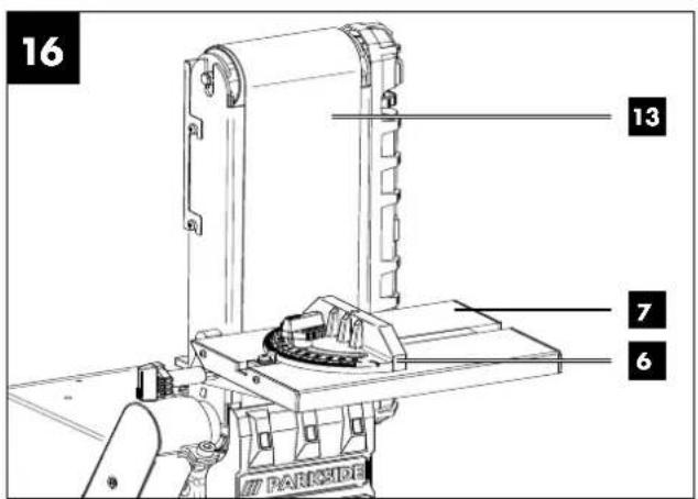
11.3 Horizontal and vertical sanding (fig. 9-11, 16)
Your sander can sand both vertically and horizontally. The worktable can be used for both applications.
- Loosen the Allen screw (12).
- Move the sanding belt (13) upwards into the desired position.
- Tighten the Allen screw (12) again to fix this position.
- In this position you can use the sanding table (7) to support the workpiece. To do this, first loosen the two Allen screws (17) and then remove the stop rail (14). The sanding table (7) can now be pushed into the hole of the holder tube (20) and fixed with the locking screw (8).
Note: Sand long workpieces in the vertical position by moving the workpiece evenly over the sanding belt (13).
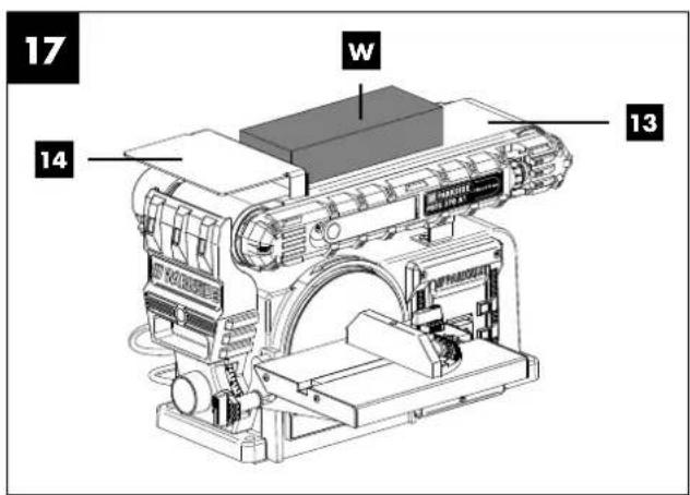
11.4 Surface sanding on the sanding belt (fig. 17)
- Hold the workpiece (W) firmly. Watch your fingers! Danger of injury!
- Keep the workpiece pressed firmly against the stop rail (14) guiding it evenly over the sanding belt (13). Attention: Be particularly careful when sanding very thin pieces and extra long pieces (perhaps even without stop rail (14)). Apply only enough pressure to allow the sanding belt (13) to remove sanded material.
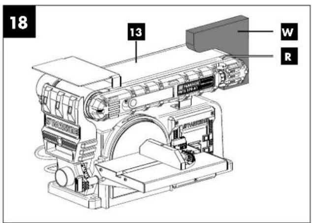
11.5 Sanding inside (concave) curves (fig. 18)
Warning: Never attempt to sand the end pieces of a workpiece on the idler drum (R). If you do so, the workpiece (W) may be ejected. Danger of injury!
Always sand concave curves using the idler drum at the sanding belt (13).
- Hold the workpiece firmly. Watch your fingers! Danger of injury!
- Guide the workpiece evenly over the sanding belt (13). Attention: Be particularly careful when sanding very thin pieces and extra long pieces.
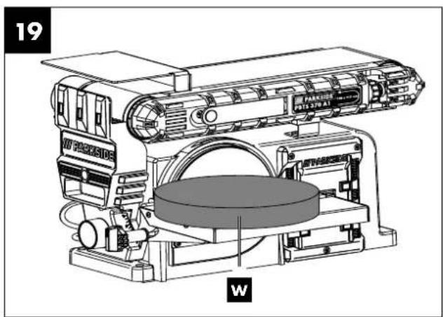
11.6 Sanding outside (convex) curves (fig. 19)
Always sand convex curves using the sanding disc by guiding the workpiece (W) from the left side to the centre of the sanding disc.
- Hold the workpiece firmly. Watch your fingers! Danger of injury!
- Press the workpiece firmly against the sanding disc moving it from the left to the centre of the sanding disc.
Warning: Never attempt to sand concave curves at the right side of the sanding disc! The workpiece may be ejected! Danger of injury!
12. Cleaning and maintenance
Warning! Pull out the mains plug before carrying out any adjustments, maintenance or repair work!
12.1 General maintenance tasks
Wipe swarf and dust off the machine from time to time with a cloth. Oil the rotating parts once monthly to extend the life of the tool. Do not oil the motor.
Do not use corrosive agents for cleaning the plastic.
12.2 General maintenance information
After using your sander, clean it completely. Regularly lubricate all moving parts.
12.3 Cleaning
Dust can collect in the belt and disc sander. Check regularly (preferably after each use) and remove dust, e. g. by blowing away or carefully with compressed air.
12.4 Service information
With this product, it is necessary to note that the following parts are subject to natural or usage-related wear, or that the following parts are required as consumables.
Wearing parts*: sanding tools, toothed belt
* not included in the scope of delivery!
12.5 Available accessories
-
Sanding belt L 915 x W 100 mm, 3 units respectively:
K 240 - article number: 7903306602
K 120 - article number: 88000212
K 180 - article number: 88000221
K 80 - article number: 88000211 -
Sanding paper ∅ 150 mm, 10 units respectively:
K 80 - article number: 88000208
K 120 - article number: 88000209
K 180 - article number: 88000220
K 240 - article number: 7903306601
- Sanding set 12 pieces – article number: 7903302601 Comprising:
3 x sanding paper grain size 80/120/180 respectively
1 x sanding paper grain size 80/120/180 respectively
- Protective goggles – article number: 7909601701
13. Storage
Store the device and its accessories in a dark, dry and frost-free place that is inaccessible to children. The optimum storage temperature lies between 5 and 30 °C.
Cover the device in stationary use after work to protect it from dust or moisture.
Store the device in portable use in the original packaging after work.
Store the operating manual with the power tool.
14. Electrical connection
The electrical motor installed is connected and ready for operation. The connection complies with the applicable VDE and DIN provisions. The customer's mains connection as well as the extension cable used must also comply with these regulations.
14.1 Damaged electrical connection cable
The insulation on electrical connection cables is often damaged.
This may have the following causes:
- Pressure points, where connection cables are passed through windows or doors.
- Kinks where the connection cable has been improperly fastened or routed.
- Places where the connection cables have been cut due to being driven over.
- Insulation damage due to being ripped out of the wall outlet.
- Cracks due to the insulation ageing.
Such damaged electrical connection cables must not be used and are life-threatening due to the insulation damage.
Check the electrical connection cables for damage regularly. Ensure that the device is disconnected from electrical power when checking for damage.
Electrical connection cables must comply with the applicable VDE and DIN provisions. Only use connection cables of the same designation.
The printing of the type designation on the connection cable is mandatory.
Safety information for replacing damaged or defective mains connection cables
Type Y
If it is necessary to replace the connection cable, this must be done by the manufacturer or their representative to avoid safety hazards.
14.2 AC motor
- The mains voltage must be 230–240 V\~.
- Extension cables up to 25 m long must have a cross-section of 1.5 mm 2 .
Connections and repair work on the electrical equipment may only be carried out by electricians.
Please provide the following information in the event of any enquiries:
• Type of current for the motor
• Data of machine type plate
• Data of motor type plate
15. Disposal and recycling
The device is supplied in packaging to avoid transport damages. This packaging is raw material and can thus be used again or can be reintegrated into the raw material cycle. The device and its accessories are made of different materials, such as metals and plastics. Take defective components to special waste disposal sites. Check with your specialist dealer or municipal administration!

The packaging is wholly composed of environmentally-friendly materials that can be disposed of at a local recycling centre.
Contact your local refuse disposal authority for more details of how to dispose of your worn-out electrical devices.
Old devices must not be disposed of with household waste!
This symbol indicates that this product must not be disposed of together with domestic waste in compliance with the Directive (2012/19/EU) pertaining to waste electrical and electronic equipment (WEEE). This product must be handed over at the intended collection point. This can be done, for example, by returning it when purchasing a similar product or delivering it to an authorised collection point for the recycling of old electrical and electronic devices. Improper handling of waste equipment may have negative consequences for the environment and human health due to potentially hazardous substances that are often contained in electrical and electronic equipment. By properly disposing of this product, you are also contributing to the effective use of natural resources. You can obtain information on collection points for waste equipment from your municipal administration, public waste disposal authority, an authorised body for the disposal of waste electrical and electronic equipment or your waste disposal company.
16. Troubleshooting
| Fault Possible cause Remedy | ||
| Motor does not start | On/off switch damaged | Replace all damaged parts before you use your sander again.Contact your local service centre or an authorised service station. Every attempt to carry out a repair, can be dangerous if it is not done by skilled personnel. |
| On/off cable damaged | ||
| On/off relay damaged | ||
| Machine becomes slower during work. | Too much pressure is applied to the workpiece. Apply less pressure to the workpiece. | |
| Sanding belt comes off the drive pulleys. | It does not run straight. Reset the track. | |
| Wood gets burnt during sanding. | Sanding disc or belt is covered with grease. | Replace belt or disc. |
| Excessive pressure was applied to the workpiece. | Reduce the pressure applied to the workpiece. | |
17. Warranty certificate
Dear Customer,
All of our products undergo strict quality checks to ensure that they reach you in perfect condition. In the unlikely event that your device develops a fault, please contact our service department at the address shown on this guarantee card. Of course, if you would prefer to call us then we are also happy to offer our assistance under the service number printed below. Please note the following terms under which guarantee claims can be made:
- These guarantee terms cover additional guarantee rights and do not affect your statutory warranty rights. We do not charge you for this guarantee.
- Our guarantee only covers problems caused by material or manufacturing defects, and it is restricted to the rectification of these defects or replacement of the device. Please note that our devices have not been designed for use in commercial, trade or industrial applications. Consequently, the guarantee is invalidated if the equipment is used in commercial, trade or industrial applications or for other equivalent activities. The following are also excluded from our guarantee: compensation for transport damage, damage caused by failure to comply with the installation/assembly instructions or damage caused by unprofessional installation, failure to comply with the operating instructions (e.g. connection to the wrong mains voltage or current type), misuse or inappropriate use (such as overloading of the device or use of non-approved tools or accessories), failure to comply with the maintenance and safety regulations, ingress of foreign bodies into the device (e.g. sand, stones or dust), effects of force or external influences (e.g. damage caused by the device being dropped) and normal wear resulting from proper operation of the device.
The guarantee is rendered null and void if any attempt is made to tamper with the device.
- The guarantee is valid for a period of 3 years starting from the purchase date of the device. Guarantee claims should be submitted before the end of the guarantee period within two weeks of the defect being noticed. No guarantee claims will be accepted after the end of the guarantee period. The original guarantee period remains applicable to the device even if repairs are carried out or parts are replaced. In such cases, the work performed or parts fitted will not result in an extension of the guarantee period, and no new guarantee will become active for the work performed or parts fitted. This also applies when an on-site service is used.
- In order to assert your guarantee claim, please contact the service partner shown below. If the complaint is within the guarantee period, we will provide you with a return slip, with which you can return your defective device free of charge to us. It would help us if you could describe the nature of the problem in as much detail as possible. If the defect is covered by our guarantee then your device will either be repaired immediately and returned to you, or we will send you a new device.
Of course, we are also happy offer a chargeable repair service for any defects which are not covered by the scope of this guarantee or for units which are no longer covered. To take advantage of this service, please send the device to our service address.
Service-Hotline (GB/IE):
+800 4003 4003
(0,00 EUR/Min.)
Service-Email (GB):
service.GB@scheppach.com
Service-Email (IE):
service.IE@scheppach.com
Service Address (GB/IE):
Forest Park & Garden
Coed Court, Taffsmead Road
Treforest, Ind. Estate, Pontypridd CF375SW

At www.lidl-service.com you can download this and many more manuals, product videos plus installation software.
The QR code takes you directly to the Lidl service page (www.lidl-service.com) and you can open your operating manual by entering the article number (IAN) 339368_2001.
Table des matières: Page:
Günzburger Straße 69
D-89335 Ichenhausen
Cher client,
Dimensions de la plaque support ....225 x 160 mm
Service-hotline (BE):
+800 4003 4003
(0,00 €/Min.)
Email du service (FR):
service.FR@scheppach.com
E-mailadres (BE):
service.BE@scheppach.com
Scheppach France Strassburg
2, Impasse Jean Millot
FR - 6700 Strasbourg
Serviceadres (BE):
Günzburger Straße 69
D-89335 Ichenhausen
Geachte klant,
9.1 Montage (afb. 1-4)
service.NL@scheppach.com
E-mailadres / Email du service (BE):
service.BE@scheppach.com
Serviceadres / Adresse du service (NL/BE):
Günzburger Straße 69
D-89335 Ichenhausen
Szanowny Kliencie,
Günzburger Straße 69
D-89335 Ichenhausen
Vážený zákazníku,
Günzburger Straße 69
D-89335 Ichenhausen
Vážený zákazník,
CE - Declaration of Conformity Translation of the original EC declaration of conformity
Article name: BELT & DISC SANDER - PBTS 370 A1
Nom d'article: PONCEUSE À BANDE/DISQUES - PBTS 370 A1
Art.-Nr. / Art. no. / Numéro d'article: 3903306974 - 3903306981; 39033069915; 39033069951
Ident.-Nr. / Ident. no. / N° d'ident.: 01001 - 28528
| 2014/29/EU | 2004/22/EC | 89/686/EC_96/58/EC | |||
| 2014/35/EU | 2014/68/EU | 90/396/EC | |||
| X | 2014/30/EU | X | 2011/65/EU* | ||
| X 2006/42/EC | |||||
| Annex IVNotified Body:Notified Body No.:Certificate No.: | |||||
Standard references:
EN 62841-1:2015; EN ISO 12100:2010; EN 55014-1:2017; EN 55014-2:2015; EN 61000-3-2:2014; EN 61000-3-3:2019
This declaration of conformity is issued under the sole responsibility of the manufacturer.
Subject to change without notice
Documents registar: Andreas Pecher
Günzburger Str. 69, D-89335 Ichenhausen
CE

Stand der Informationen · Last Information Update · Version des informations · Stand van de informatie · Stan informacji · Stav informaci · Stav informaci
Update: 04 / 2020 - Ident.-No.: 339368_2001_39033069915


- BAND- UND TELLERSCHLEIFER PBTS 370 A1 BELT & DISC.SANDER PBTS 370 A1 PONCEUSE À BANDE/DISQUES PBTS 370 A1
- BAND- EN SCHIJFSCHUURMACHINES
- INHALT
- SEITE
- VEREHRTER KUNDE
- TABLE OF CONTENTS: PAGE
- EXPLANATION OF THE SYMBOLS ON THE DEVICE
- INTRODUCTION
- MANUFACTURER
- DEAR CUSTOMER
- NOTE
- PLEASE CONSIDER
- DEVICE DESCRIPTION (FIG. 1-19)
- SCOPE OF DELIVERY
- PROPER USE
- SAFETY INFORMATION
- GENERAL POWER TOOL SAFETY WARNINGS
- SAVE ALL WARNINGS AND INSTRUCTIONS FOR FUTURE REFERENCE
- WORK AREA SAFETY
- ELECTRICAL SAFETY
- PERSONAL SAFETY
- POWER TOOL USE AND CARE
- SERVICE
- HAVE YOUR POWER TOOL SERVICED BY A QUALIFIED REPAIR PERSON USING ONLY IDENTICAL REPLACEMENT PARTS
- ADDITIONAL SAFETY INSTRUCTIONS FOR THE BELT AND DISC SANDER
- RESIDUAL RISKS
- TECHNICAL DATA
- WEAR HEARING PROTECTION
- BEFORE COMMISSIONING
- 8.1 UNPACKING
- DANGER
- 8.2 GENERAL NOTES
- WARNING
- ATTACHMENT AND OPERATION
- 9.1 ASSEMBLING THE MACHINE (FIG. 1-4)
- 9.2 CHANGING THE SANDING BELT (FIG. 5-8)
- 9.3 ADJUSTING THE SANDING BELT
- 9.4 MOVING THE SANDING POSITION OF THE SANDING BELT (FIG. 9-11)
- 9.5 REPLACING THE SANDING PAPER ON THE SANDING DISC (FIG. 12)
- 9.6 USE AS A STATIONARY TOOL
- 9.7 USE AS A PORTABLE TOOL
- 9.8 ON/OFF SWITCH (5) (FIG. 13)
- 9.9 SANDING
- 9.10 DUST EXTRACTION CONNECTION
- TRANSPORT
- WORKING INSTRUCTIONS
- 11.1 BEVEL SANDING (FIG. 14)
- 11.2 SANDING SMALL END SURFACES USING THE TRANSVERSE STOP (FIG. 15A, 15B)
- 11.3 HORIZONTAL AND VERTICAL SANDING (FIG. 9-11, 16)
- 11.4 SURFACE SANDING ON THE SANDING BELT (FIG. 17)
- 11.5 SANDING INSIDE (CONCAVE) CURVES (FIG. 18)
- 11.6 SANDING OUTSIDE (CONVEX) CURVES (FIG. 19)
- CLEANING AND MAINTENANCE
- 12.1 GENERAL MAINTENANCE TASKS
- 12.2 GENERAL MAINTENANCE INFORMATION
- 12.3 CLEANING
- 12.4 SERVICE INFORMATION
- 12.5 AVAILABLE ACCESSORIES
- STORAGE
- ELECTRICAL CONNECTION
- 14.1 DAMAGED ELECTRICAL CONNECTION CABLE
- SAFETY INFORMATION FOR REPLACING DAMAGED OR DEFECTIVE MAINS CONNECTION CABLES
- TYPE Y
- 14.2 AC MOTOR
- DISPOSAL AND RECYCLING
- OLD DEVICES MUST NOT BE DISPOSED OF WITH HOUSEHOLD WASTE
- TROUBLESHOOTING
- WARRANTY CERTIFICATE
- TABLE DES MATIÈRES: PAGE
- CHER CLIENT
- GEACHTE KLANT
- 9.1 MONTAGE (AFB. 1-4)
- SZANOWNY KLIENCIE
- VÁŽENÝ ZÁKAZNÍKU
- VÁŽENÝ ZÁKAZNÍK
- CE - DECLARATION OF CONFORMITY TRANSLATION OF THE ORIGINAL EC DECLARATION OF CONFORMITY
- STANDARD REFERENCES
- EN 62841-1:2015; EN ISO 12100:2010; EN 55014-1:2017; EN 55014-2:2015; EN 61000-3-2:2014; EN 61000-3-3:2019
Brand : PARKSIDE
Model : PBTS 370 A1
Category : Sander