DF 500 QPlus - Electric router FESTOOL - Free user manual and instructions
Find the device manual for free DF 500 QPlus FESTOOL in PDF.

| Product type | Domino tenon router bit |
| Rated power | 420 W |
| No-load speed | 25,500 rpm |
| Max. routing depth | 28 mm |
| Max. routing width | 23 mm + ∅ of router bit |
| Max. router bit diameter | 10 mm |
| Thread of drive shaft | M6 x 0.75 |
| Weight (without cable) | 3.2 kg |
| Protection class | II |
| Sound pressure level | 84 dB(A) |
| Sound power level | 95 dB(A) |
| Vibration emission (ah) | 3.0 m/s² (K=1.5 m/s²) |
| Depth settings | 12, 15, 20, 25, 28 mm (by lever) |
| Router bit height adjustment | By slide plate thickness 16-40 mm or continuous vernier |
| Angular stop | 0° to 90° with detents at 0°, 22.5°, 45°, 67.5°, 90° |
| Dust extraction connection | Diameter 27 mm |
| Machinable materials | Soft and hard woods, particle boards, plywood, fiber boards |
| Maintenance of guides | Light resin-free oil (e.g., sewing machine oil) |
| Supplied accessories | Open-end wrench 8, stop extension, stop reducers |
| Safety | Column block, spindle lock, automatic brush cut-off |
Frequently Asked Questions - DF 500 QPlus FESTOOL
User questions about DF 500 QPlus FESTOOL
0 question about this device. Answer the ones you know or ask your own.
Ask a new question about this device
Download the instructions for your Electric router in PDF format for free! Find your manual DF 500 QPlus - FESTOOL and take your electronic device back in hand. On this page are published all the documents necessary for the use of your device. DF 500 QPlus by FESTOOL.
USER MANUAL DF 500 QPlus FESTOOL
GB Original operating manual - Dowel jointer 12
natural_image
Exterior view of a black-and-white industrial power saw with coiled cable (no visible text or symbols)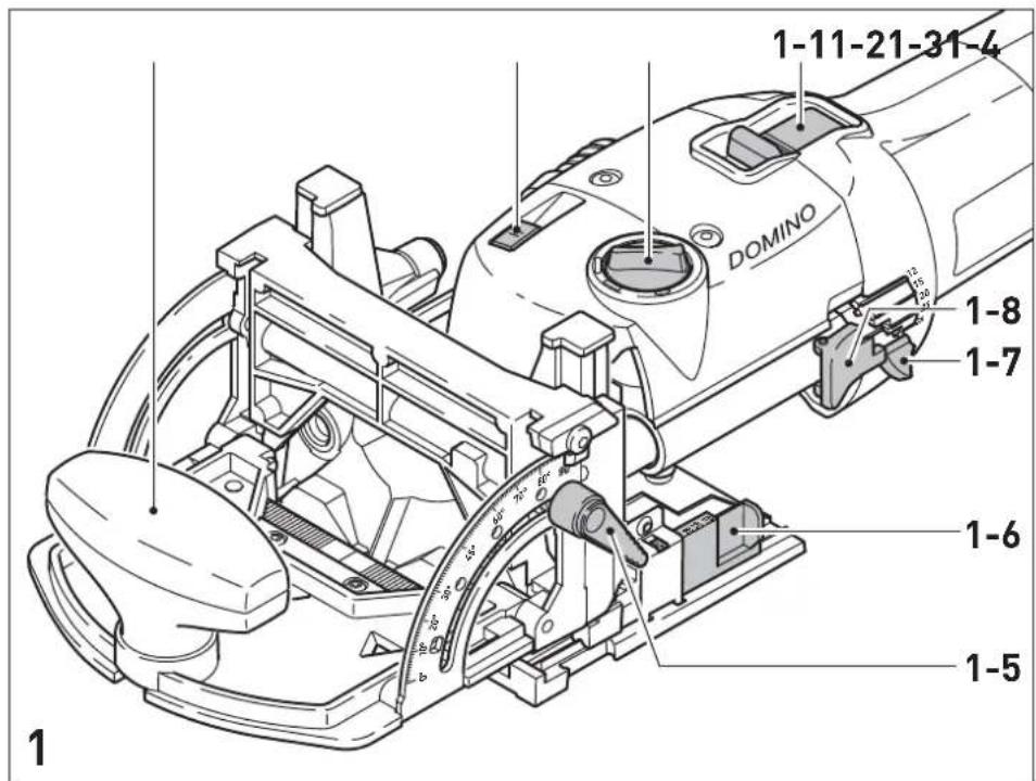
text_image
1-11-21-31-4 DOMINO 1-8 1-7 1-6 1-5 1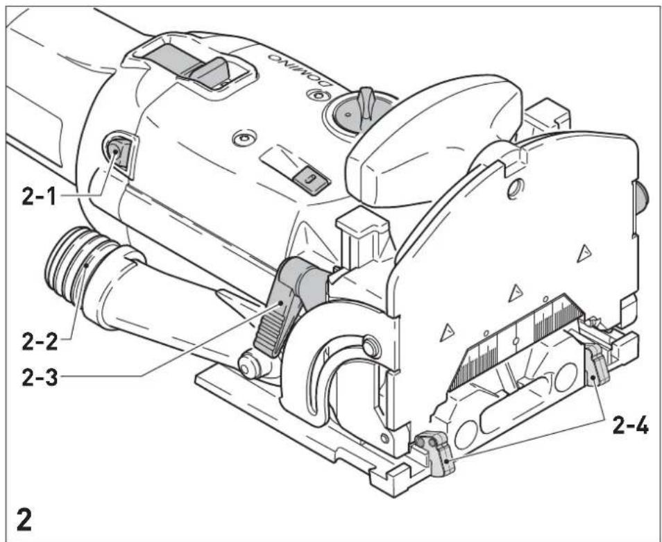
text_image
2 2-1 2-2 2-3 2-4 2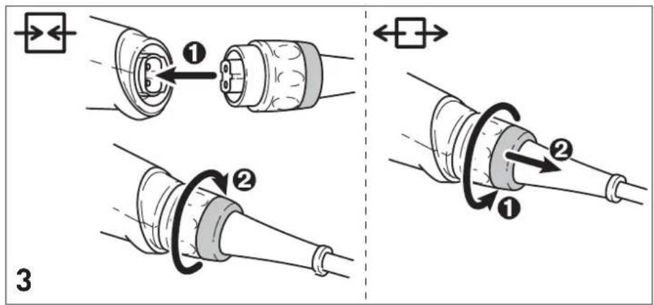
text_image
Technical diagram illustrating cable connector assembly steps with numbered instructions and directional arrows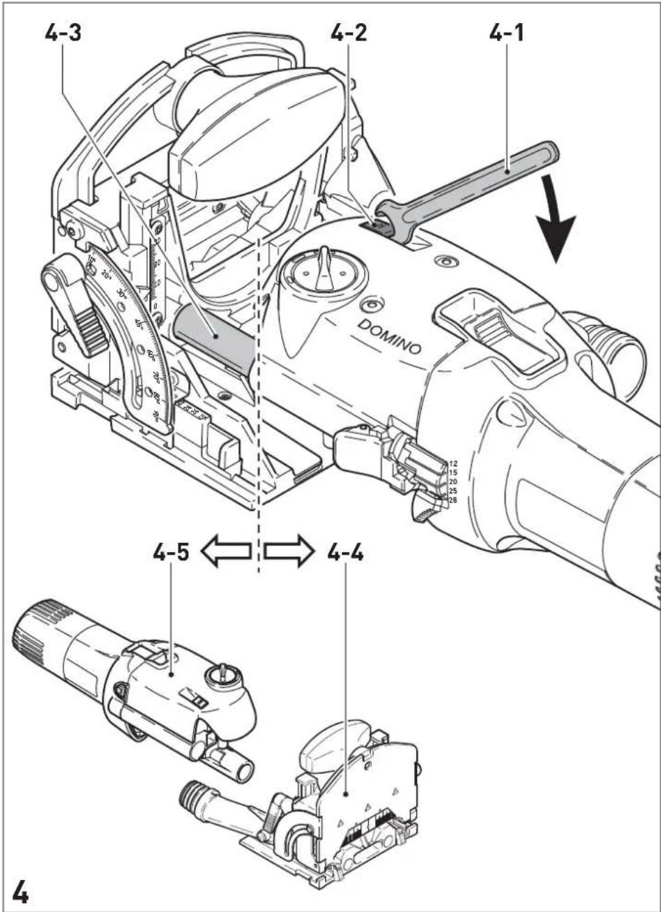
text_image
4-3 4-2 4-1 DOMINO 12 15 20 25 28 4-5 4-4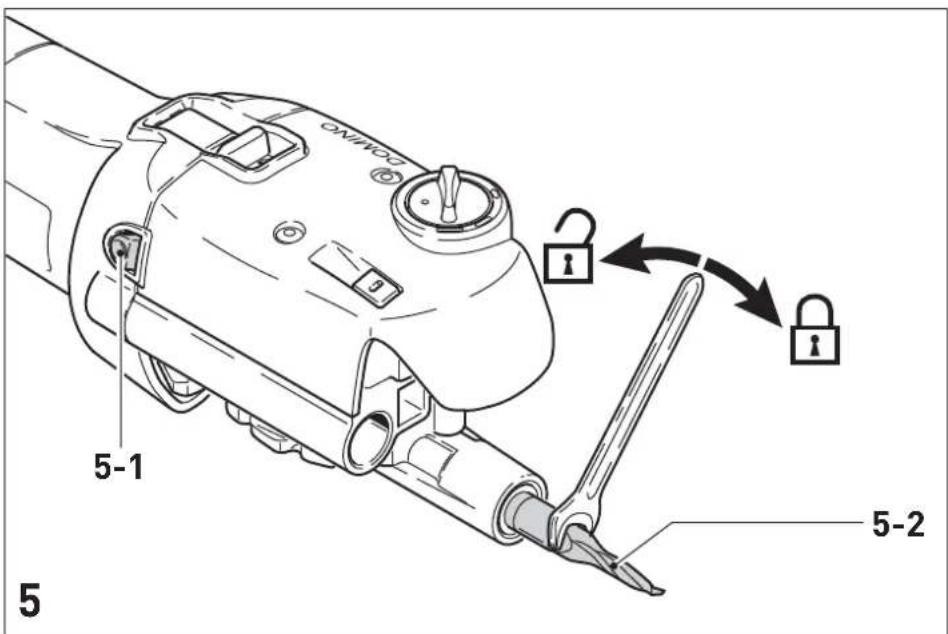
text_image
5-1 5-2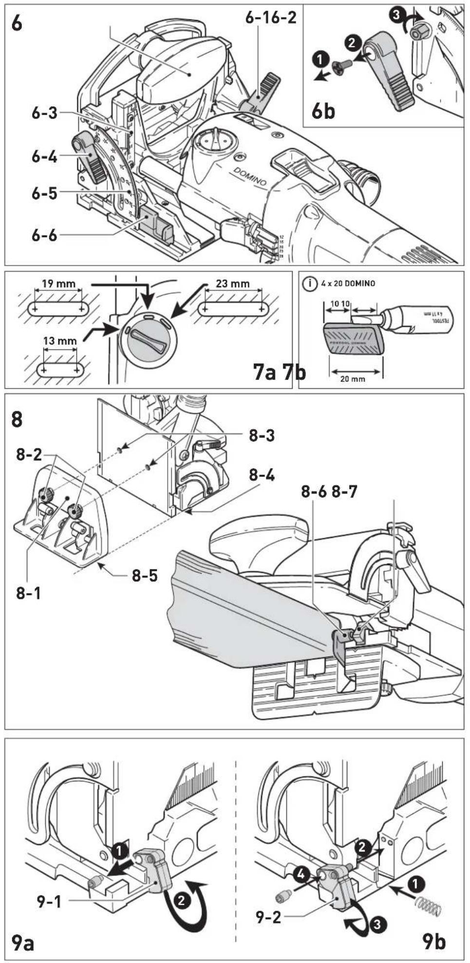
10-3
Wolfgang Zondler
Head of Research, Development and Technical Documentation
Wendlingen, 2016-12-14
Declaration of Conformity
We as the manufacturer Festool GmbH, Wertstraße 20, 73240 Wendlingen, Germany declare under our sole responsibility that the product(s):
Designation:
Designation of Type(s):
Serial number(s) ^1) :
Joining machine
DF 500 Q
498621, 498622
fulfills all the relevant provisions of the following UK Regulations:
S.I. 2008/1597
S.I. 2016/1091
S.I. 2012/3032
Supply of Machinery (Safety) Regulations 2008
Electromagnetic Compatibility Regulations 2016
Restriction of the Use of Certain Hazardous Substances in Electrical and Electronic Equipment Regulations 2012
and are manufactured in accordance with the following designated standards:
• BS EN 60745-1:2009 + A11:2010
• BS EN 60745-2-19:2009 + A1:2010
• BS EN 55014-1:2017
• BS EN 55014-2:2015
• BS EN IEC 61000-3-2:2019
• BS EN 61000-3-3:2013
• BS EN IEC 63000:2018
1) in the specified serial number range (S-Nr.) from 400000000 - 499999999

Place and date of declaration: Wendlingen, 03.05.2021
Signed on behalf of and in name of Festool GmbH

text_image
Markus Stark Head of Productdevelopmenti.V.Q.Bordt
Ralf Brandt
Head of Productconformity
D
Dowel jointer Table of contents
1 Machine features 12
2 Technical data 12
3 Pictograms....12
4 Intended use 12
5 Safety instructions....12
6 Power supply and start-up 13
7 Machine settings....13
8 Working with the machine....14
9 Maintenance and care 15
10 Accessories, tools.... 15
11 Environment....15
12 Example applications.... 16
13 Fault correction 16
1 Machine features
[1 1] ON/OFF switch
[1 2] Rotary switch for Domino dowel-hole width
[1 3] Unlocking device for motor unit / guide frame
[1 4] Auxiliary handle
[1 5] Clamping lever for angle guide
[1 6] Selection slide for material thickness
[1 7] Notch lever for Domino dowel-hole depth
[1 8] Notch lever lock
[2 1] Spindle lock
[2 2] Extraction nozzle
[2 3] Clamping lever for jointing height adjustment
[2 4] Stop latch
The specified illustrations can be found at the beginning of the operating instructions.
2 Technical data
| Power 420 W |
| Speed (no load) 25 500 min |
| Jointing depth, max. 28 mm |
| Jointing width, max. 23 mm + jointer bit |
| diameter |
| Jointing bit diameter, max. 10 mm |
| Connecting thread of drive shaft M6 x 0.75 |
| Weight (excluding cable) 3.2 kg |
| Degree of protection / II |
3 Pictograms

, Danger!

r ear protection!

Wear protective goggles!

Manual, read the instructions.

r a protective mask!

CE marking: Confirms the conformity of the power tool with the European Community directives.

UKCA marking: The United Kingdom Conformity Assessed symbol is a marking for products being placed on the market in the United Kingdom. It is a manufacturers indication that the product is in conformance with the relevant regulations in the UK.
4 Intended use
The Domino dowel jointer is designed to produce Domino dowelled joints in soft and hard wood, chip board, plywood and fibre boards. All applications beyond this are regarded as unspecified use. The Domino dowel jointer is designed and approved for use by trained persons or specialists.

The user is liable for damage and injury resulting from incorrect usage!
5 Safety instructions
5.1 General Safety Rules

WARNING! Read all safety warnings and all instructions.
Failure to follow the warnings and instructions may result in electric shock, fire and/or serious injury.
Save all warnings and instructions for future reference.
The term „power tool“ in the warnings refers to your mains-operated (corded) power tool or battery-operated (cordless) power tool.
5.2 Tool-specific safety rules
- Mounting tools must be rated for at least the speed marked on the tool. Mounting tools running over rated speed can fly apart and cause injury.
- Always use the guard. The guard protects the operator from broken mounting tool fragments and unintentional contact with the mounting tool.
- Hold power tool by insulated gripping surfaces, because the cutter may contact its own cord. Cutting a "live" wire may make exposed metal parts of the power tool "live" and could give the operator an electric shock.
- The DF 500 Q must only be fitted with the jointer bits offered by Festool for this purpose. The
use of other jointer bits is prohibited due to the increased risk of injury.
- Never work with blunt or damaged jointer bits. Blunt or damaged jointer bits can lead to a loss of control of the power tool.
- When the motor unit is released, it must move back actuated by spring force so that the jointer bit disappears completely in the protective cover. If this does not happen, the machine must be switched off immediately and repaired before reuse.
- Only for AS/NZS: The tool shall always be supplied via residual current device with a rated residual current of 30 mA or less.

To protect your health, wear a P2 protective mask.
5.3 Noise and vibration information
The typical values determined in accordance with EN 60745 are:
Sound-pressure level 84 dB(A)
Sound-power level 95 dB(A)
Measuring uncertainty allowance K = 3 dB

r ear protection!
Vibration emission value a_h (vector sum for three directions) and uncertainty K measured in accordance with EN 60745:
Vibration emission value a _h = 3,0 m/s^2 K = 1,5 m/s²
The specified emissions values (vibration, noise) – are used to compare machines.
- They are also used for making preliminary estimates regarding vibration and noise loads during operation.
- They represent the primary applications of the power tool.
Increase possible for other applications, with other insertion tools or if not maintained adequately. Take note of idling and downtimes of machine!
6 Power supply and start up

The mains voltage must correspond to the specification on the rating plate.

Always switch the machine off before connecting or disconnecting the mains lead!
See Fig. 2 for connection and disconnection of the power cable.
To switch on, push the switch [1 1] forwards until it engages. Pressing the back end of the switch is sufficient to release the switch-on lock and switch the machine off.
7 Machine settings

Always remove the power supply plug from the socket before carrying out any work on the machine.
7.1 Changing tools
Required tools: fork wrench a/f 8 (supplied).

Always wear protective gloves during tool change due to the risk of injury from the sharp tool cutters.
a) Removing the tool
- Lift the unlocking lever [4 2] until it audibly engages with the fork wrench [4 1].
- Separate the motor unit [4 5] and the guide frame [4 4].
- Press and hold in the spindle lock [5 1].
- Release and unscrew the jointer bit [5 2] with the fork wrench.
- Release the spindle lock.
b) Inserting the tool
- Before inserting a new jointer bit, ensure that the machine, the guide frame and the guides [4 3] are clean. Remove any contamination that may be present. Only use sharp, undamaged and clean tools.
- Press and hold in the spindle lock [5 1].
- Use the fork wrench to screw on the jointer bit [5 2].
- Release the spindle lock.
- Slide the guide frame onto the motor unit until it audibly engages.
7.2 Adjusting the milling depth
- Open the notch lever lock [1 8] by pressing it.
- Use the locking lever [1 7] to set the desired jointing depth (12 mm, 15 mm, 20 mm, 25 mm, 28 mm). For the jointer bit with a diameter of 5 mm, only jointing depths of 12 mm, 15 mm and 20 mm are permitted due to its short shank length.
- Release the notch lever lock again.
A special cutter is available for the DOMINO dowel 4x20 mm (due to risk of breakage). Note the following when using this cutter (D 4-NL 11 HW-DF 500):
- Set the routing depth to 20 mm using the stop lever [1 7]. The actual routing depth is 10 mm. The dowel can only be positioned centrally (see Fig. 7b).

Ensure that the jointing depth is at least 3 mm smaller than the workpiece thickness. Otherwise the jointer bit can emerge from the workpiece at the rear side, which involves an increased risk of injury.
7.3 Setting jointing height a) with selection slide
- Release the clamping lever [6 1] for jointing height adjustment.
- Using the additional handle [6 2], raise the front section of the guide frame.
- Use the slide [6 6] to set the desired board thickness (16 mm, 20 mm, 22 mm, 25 mm, 28 mm, 36 mm, 40 mm).
- Press the front section of the guide frame downwards as far as the stop.
- Close the clamping lever [6 1].
b) freely selectable
- Release the clamping lever [6 1] for jointing height adjustment.
- Using the additional handle [6 2], raise the front section of the guide frame.
- Push the slide [6 6] to the stop in direction motor unit.
- Set the desired jointing height using the scale [6 3] by moving the front section of the guide frame vertically.
- Close the clamping lever [6 1].
7.4 Setting angle guide
- Release the clamping lever for the angle guide [6 4].
- Set the desired angle: using the scale [6 5] steplessly from 0^ - 90^ , or in notches at 0^ , 22.5^ , 45^ , 67.5^ , 90^ .
- Close the clamping lever [6 4].
Mitre cutting thin workpieces
- Set the desired angle.
- Release the clamping lever [6 1] for jointing height adjustment.
- Push the slide [6 6] to the stop in direction motor unit.
- Slide the angle stop all the way down.
- Close the clamping lever [6 1].

Always release the clamp lever [6 1] before resetting the angle stop.
7.5 Setting dowel hole width

Reliable setting of the dowel-hole width with the rotary switch [1 2] is only possible with the machine running! The following dowel-hole settings are possible (Fig. 7a):
13 mm + jointer bit diameter
19 mm + jointer bit diameter
23 mm + jointer bit diameter
7.6 Dust extraction

Always connect the machine to a dust extractor. You can connect a Festool extractor with an extractor hose diameter of 27 mm to the extractor connector [2 2].
7.7 Additional stop with extension
The additional stop [8 1] can be used to enlarge the contact surface when jointing on the workpiece edge, thus allowing safer guidance of the machine.
The distance to the centre of the routed hole can be reduced from 37 mm to 20 mm using the two integral stop spacers [8 6], allowing you to position the dowel closer to the edge.
- Secure the additional stop to the threaded bores [8 3] on the guide frame using both screws [8 2], whereby the contact areas of the support ring [8 5] and the table [8 4] must be level with one another.
- Swivel one of the distance spacers [8 6] outwards to reduce the distance (see Fig. 8). The spacer aligns automatically with the stop latch [8 7].
8 Working with the machine
Wood is a natural, non-homogenous material and because of this, its dimensions will most likely deviate slightly during processing, even if the machine is set accurately. Machine handling also influence the degree of working accuracy (e.g. fast-feed speed). Furthermore, the dimensions of wooden DOMINOs may vary (for example, due to humidity), regardless of how they are stored. All of these factors influence the dimensional accuracy of manufactured dowel holes and dowelling joints. Numerous tests have been run to produce an average figure for these dimensional discrepancies. The dimensions of the machine and DOMINO dowels are based on these averages. If a lateral offset of approx. 0.03 mm - 0.04 mm occurs when two workpieces are joined together, you have the option of replacing the stop latches [2 4] fitted on delivery with correction stop latches. These latches are 0.15 mm narrower and reduce the lateral clearance of the dowel holes in relation the edge of the workpiece (see Chapter 14).
Prior to processing the final workpiece, it is advisable to optimise the dowel-hole depth, width and diameter using a sample workpiece.

se observe the following rules when working:
- Always secure the workpiece in such a manner that it cannot move while being sawed.
- Always hold the Domino dowel jointer with both hands at the motor housing and at the additional handle. This reduces the risk of injury and is a prerequisite for precise work.
- Close the clamping lever for jointing height adjustment [2 3] and the clamping lever for the angle guide [1 5] so that accidental release during operation is impossible.
- Adapt the feed rate to the jointer bit diameter and material. Work with a constant feed rate.
- Only lay the Domino dowel jointer aside when the jointer bit has come to a complete standstill.
- Use the machine only with the guide frame mounted.
Procedure
Proceed as follows to create a dowelled joint:
- Select a Domino dowel and insert a matching jointing bit in the Domino dowel jointer (Chap. 7.1).
- Set the jointing depth (Chap. 7.2). The jointing depth must be at least 3 mm smaller than the workpiece thickness so that the dowelled joint is supportable.
- Set the jointing height to correspond to the workpiece thickness (Chap. 7.3).
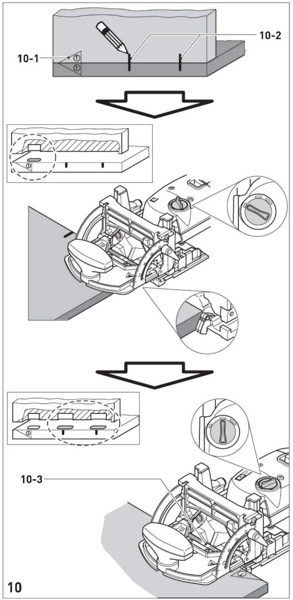
- Mark the areas on the workpiece that belong together [10 1] so that you will be able to join them correctly again once you have cut the dowel holes.
- Position the two workpieces to be joined against one another and mark the desired positions of the dowels with a pencil [10 2].
- Set the desired dowel-hole width (Chap. 7.5). Our recommendation: Cut the first hole without play (dowel-hole width = Domino dowel width), and the remaining dowel holes to the next largest dowel-hole width (Fig. 10). The first dowel hole therefore serves as a reference dimension, whereas the remaining dowel holes have tolerance for manufacturing inaccuracies.
- Cut the dowel holes: a) the first dowel hole by placing the stop latch at the side edge of the workpiece,
b) the following dowel holes according to the pencil markings made beforehand and the scale of the viewing window [10 3].
9 Maintenance and care

Always remove the power supply plug from the socket before carrying out any work on the machine.

All maintenance and repair work which requires the motor casing to be opened may only be carried out by an authorised service centre.

Customer service and repair. Only through manufacturer or service workshops: Please find the nearest address at: www.festool.com/Service
Use only original Festool spare parts! Order No. at: www.festool.com/Service

The Domino dowel jointer is to a large extent maintenance-free. However, we recommend an annual inspection and/or a check after approx. 100 operating hours at an authorised customer service workshop. This is for the safety of the user and the value stability of the Domino dowel jointer. Always keep the machine and the ventilation slots clean.
Dust deposits must be removed from the guides [4 3] . Oil the guides regularly and lightly with resin-free oil (e.g. sewing machine oil).
To secure the clamp lever (see Fig. 6b):
- Remove the clamp lever and tighten the hexagon screw.
- Attach the clamp lever to the hexagon screw again.
The tool is fitted with special motor brushes with an automatic cut-out. When the brushes become worn the power supply is shut off automatically and the tool comes to a standstill.
10 Accessories, tools

For your own safety, use only original Festool accessories and spare parts.
Festool offers extensive accessories that enable you to use your machine effectively for a wide variety of applications, e.g.: routing circle, guide rails with rows of holes, routing aid, router base for bench-mounted use.
The accessory and tool order number can be found in the Festool catalogue or on the Internet under „www.festool.com“.
11 Environment
Do not throw the power tool in your household waste! Dispose of the machine, accessories and packaging at an environmentally-responsible recycling centre! Observe the valid national regulations.
EU only: In accordance with European Directive on waste electrical and electronic equipment and implementation in national law, used electric power tools must be collected separately and handed in for environmentally friendly recycling.
Information on REACH:
www.festool.com/reach
12 General information
Imported into the UK by
Festool UK Ltd
1 Anglo Saxon Way
Bury St Edmunds
IP30 9XH
Great Britain
12 Example applications
(The following images A1 to A6.3 are on a separate enclosed sheet).
| A1.1 A1.4 Stable and non-twisting mitred frame joint. |
| A2 Very stable block frame joint. |
| A3 Very stable and non-twisting wood joints in frame and chair construction. |
| A4.1 A4.3 Stable, non-twisting and precisely fitting board joint (mitred). |
| A5.1 Stable and precisely fitting board joint (butted). |
| A5.2 Setting the Domino dowel jointer for board joint (butted), end face dowel hole. |
| A5.3 Setting the Domino dowel jointer with additional stop for board joint (butted). |
| A6.1 Stable and precisely fitting board joint (centred). |
| A6.2 Setting the Domino dowel jointer for board joint (centred). |
| A6.3 Setting the Domino dowel jointer for board joint (centred), end face dowel hole. |
13 Fault correction
(The following images B1 to B6 are on a separate enclosed sheet).
| Fault Cause Adjustment | |||
| B1 | burns blunt jointer bit use | sharp jointer bit | |
| B2 | expansion of dowel hole | jointing depth excessive (greater than 20 mm) with 5 mm jointing bit | reduce jointing depth |
| B3 | dowel penetrates workpiece | incorrect workpiece thickness and/or jointing depth | adapt workpiece thickness and/or jointing depth |
| B4 | Tears at edge of dowel hole | excessive feed rate reduce feed rate | |
| B5 | dowel hole not parallel to workpiece edge | workpiece has shifted during processing | secure workpiece properly |
| B6 | dowel hole not at right angles (90°) to work-piece surface | a) deposits (e.g. chips) below the base plateb) angle guide not set exactly to 90°c) worked on without additional stop | a) remove depositsb) set angle guide to 90° exactlyc) use additional stop |
| 9a,9b | The position of the dowel holes, which were created with the left and right stop latch, does not exactly match (different distance to workpiece edge). | The midpoint between the two stop latch is not exactly in the midpoint of the swivel range of the jointer bit. | Remove one of the stop latches [9 1] (Fig. 9a). Attach one of the accompanying stop latches [9 2] to the dowel jointer (Fig. 9b). These stop latches are narrower and allow you to make more accurate adjustments. |