
Aida - Loudspeaker Sonus Faber - Free user manual and instructions
Find the device manual for free Aida Sonus Faber in PDF.
| Brand | Sonus Faber |
| Model | Aida |
| Product type | Passive acoustic speaker |
| Configuration | Multi-way system: front/rear tweeter, front woofer, infra-woofer, Sound Field Shaper |
| Connection terminals | 3 pairs (MID HIGH, LOW, DEEP LOW) |
| Connection modes | Standard, Bi-wiring, Tri-wiring, Bi-amping, Tri-amping |
| User adjustments | LOW DAMP (bass attenuation), HIGH (treble level), DEPTH (Sound Field Shaper) |
| Recommended amplification | Generous, undistorted power, suitable for room size |
| Cabinet material | Wood |
| Finish | Wood, glass, metal |
| Included accessories | Transport trolley, 2 large Allen keys, 2 small Allen keys, microfiber cloth, cleaning kit, 4 wire tensioners, 4 rear feet with threaded pivot, 4 locking rings, 4 magnetic sub-spikes, 2 dust covers |
| Warranty | Covers manufacturing defects according to national regulations |
| Warranty conditions | Do not disassemble or modify by unauthorized personnel; keep original packaging |
| Safety | Do not place liquid objects; keep children at >50 cm; avoid magnetic fields; do not connect to 100V system |
| Maintenance | Clean with soft microfiber cloth and provided product; avoid waxes, detergents, alcohol |
| Membrane cleaning | Use a soft brush for dust |
| Protection | Use dust covers during prolonged inactivity |
| Disposal | Comply with WEEE directive; do not dispose with household waste |
| Compliance standards | IEC EN 60065, 55013, 55020, 61000-6-1, 61000-6-3; directives 2014/30/EU, 2011/65/EU, 2012/19/EU |
| Manufacturer | Sonus Faber SpA, Via Antonio Meucci, 10 - 36057 Arcugnano (VI) Italy |
| After-sales service | customerservice@sonusfaber.com; distributors at sonusfaber.com |
Frequently Asked Questions - Aida Sonus Faber
User questions about Aida Sonus Faber
0 question about this device. Answer the ones you know or ask your own.
Ask a new question about this device
Download the instructions for your Loudspeaker in PDF format for free! Find your manual Aida - Sonus Faber and take your electronic device back in hand. On this page are published all the documents necessary for the use of your device. Aida by Sonus Faber.
USER MANUAL Aida Sonus Faber
Filippo Fanton - CEO
We would like to thank and congratulate you for having chosen Aida for listening to your favourite Music.
While these exceptional loudspeakers are designed to immediately meet your highest expectations, our aim is to ensure that you obtain the best possible listening experience, and it is therefore recommended to read this user and maintenance instruction manual carefully prior to installation.
Should you have any doubts or enquiries, please contact your sales point's technical staff, the official Sonus faber distributor in your country, or Sonus faber directly by writing to customerservice@sonusfaber.com.
Finally, we highly suggest registering online with the website www.sonusfaber.com in order to keep up to date on all the latest news, initiatives and promotions offered by Sonus faber.
Enjoy
your
music!
1.2 WARRANTY AND AFTER SALES SUPPORT
Aidaloudspeakers are designed and manufactured according to the highest quality standards. Should however a fault or a malfunction occur, the loudspeakers are covered by warranty, in compliance with the regulations in force in the country where the loudspeakers were purchased.
In such cases, please contact the Sonus faber dealer from whom you purchased your loudspeakers, or the official Sonus faber distributor for your country; the contact information for all the distributors can be found on our website http://sonusfaber.com/en-us/distributors.
The following should also be kept in mind for your convenience:
- The warranty on the loudspeakers covers any manufacturing defects;
- Keep the receipt as proof of purchase to show to the retailer if necessary;
- Keep the loudspeakers' original packaging so that they can be transported without suffering damage if they need to be shipped to an authorised service centre;
- The loudspeakers must be accompanied by a description of the malfunction or defect encountered.
The product's warranty will be void under the following conditions:
• If the product has been disassembled or modified by persons other than a Sonus faber authorised service centre;
- If the product has been used in a manner that is not consistent with the indications contained within this manual.
1.3 DECLARATION OF CONFORMITY

Sonus faber SpA with headquarters at Via Antonio Meucci, 10 - 36057 Arcugnano (VI) Italy, hereby declares under its sole responsibility that the passive loudspeaker system
Aida
to which this declaration refers, is in compliance with:
Directives:
2014/30/UE (EMC) Electromagnetic Compatibility.
2011/65/UE (RoHS) Restriction of the use of certain hazardous substances in electrical and electronic equipment.
2012/19/UE (RAEE) Waste electrical and electronic equipment.
2006/1907/CE (REACH) Registration, evaluation, authorisation and restriction of chemical substances.
Standards:
CEI EN 60065:2016
Audio, video and similar electronic apparatus - Safety requirements.
CEI EN 55013:2014
Sound and television broadcast receivers and associated equipment - Radio disturbance characteristics.
CEI EN 55020:2016
Sound and television broadcast receivers and associated equipment; Immunity characteristics - Limits and methods of measurement.
CEI EN 61000-6-1:2013
Electromagnetic compatibility (EMC) Part 4-3: Testing and measurement techniques; Radiated, radio-frequency, electromagnetic field immunity test.
CEI EN 61000-6-3:2014
Generic standards; Immunity for residential, commercial and light-industrial environments.
Filippo Fanton - CEO
2 SAFETY INFORMATION
- This instruction manual must be read carefully and kept in an accessible location for any needs that may arise.
- Adjust the support feet in such a way as to obtain the best possible stability.
- Avoid placing heavy objects upon the loudspeaker, as these can compromise its stability.
- If the loudspeakers are to be positioned upon a raised support surface (e.g. mezzanines, wooden boosters, etc.), check beforehand to make sure that the surface is capable of bearing their weight. Also make sure that there is sufficient friction to prevent the loudspeakers from moving due to the vibrations generated under normal operating conditions.
- Do not place any objects containing flammable liquids, substances, or liquefiable substances upon the loudspeaker.
- Use one of the connection diagrams contained in this instruction manual. The connection of two or more loudspeakers in parallel can damage your amplifier. If in doubt, contact your dealer.
- Keep at a safe distance from the speakers while the audio system is operating at high volume. This can cause permanent damage to your hearing! Children must be kept at a safety distance of least 50 cm from the loudspeaker.
- The speakers generate an electromagnetic field that is harmless to humans and pets, but can compromise the proper functionality of electronic equipment, such as CRT monitors or TVs, when placed in close proximity. If this occurs, increase
the equipment's distance from the loudspeakers. Do not place credit cards or other similar magnetic stripe cards on the loudspeaker.
- The technology underlying the speakers' functionality is based on the principles of electromagnetism, and the user should therefore avoid operating equipment that generates strong electromagnetic fields, as these could affect the loudspeaker's proper functionality. Avoid placing transmitting devices such as mobile phones, cordless phones, intercom systems, etc., upon the loudspeakers' cabinet.
- Do not connect the loudspeakers directly to a constant voltage sound distribution system (100 V, 70.7 V or similar). This could result in a serious system overload, with possible damage to the loudspeaker system and/or the amplifier unit.
- Do not place audio cables and electrical power cables in close proximity to one another. An electromagnetic field is present in the vicinity of the power cables, which can cause an unpleasant humming noise. In this case, increase the distance between the audio cables and the power cables.
- The banana plug sockets on the loudspeakers' cable terminals are blocked by removable plugs in order to prevent them from being accidentally connected to unprotected electrical outlets. Only remove the red and black plastic caps if you intend to use this type of connection, and make sure that the other end of the cable is connected to the amplifier's power output terminals.
3 INSTALLATION
3.1 UNPACKING
Perform the unpacking operations as follows. Refer to the images contained in chapter 7 Illustrations.
Respect the following general indications:
- Keep all the packaging elements for any future transport operations;
- Do not wear any watches, bracelets, rings, etc., in order to avoid scratching the loudspeakers and their finishes. The same care must be taken in order to protect the loudspeakers from any metal elements present on the clothes you are wearing, such as zippers, buttons, belt clasps, rivets, etc..
 | Hold the loudspeakers securely with both hands in order to avoid dropping them.The indicated operations can be performed more safely and conveniently by two people. |
 | The packaging materials can cause pollution.These materials must not be disposed of as domestic waste, and must be brought to a waste collection and recycling centre. |
 | Do not leave the packaging materials within the reach of children!They could pose a risk of poisoning or suffocation if ingested. |
3.1.1 PACKAGING CONTENTS
In addition to the loudspeakers, the packaging also contains:
1 Support and transport trolley
1 Photo book
1 Manual
2 Large hex wrenches
2 Small hex wrenches
2 Cleaning cloths
2 Cleaning kits
4 Grilles
4 Rear support feet with threaded pins
4 Lock nuts for blocking the front support feet's pins
4 Magnetic floor discs
2 Fabric dust guards
If one or more of these items is missing, notify the retailer from whom the product was purchased.
3.1.2 SPEAKER PREPARATION
The following operations serve to prepare the loudspeakers for their placement within the listening environment. The two loudspeakers must be moved one at a time using the special support and transport trolley (henceforth referred to as the "trolley").
The trolley must be removed from the first loudspeaker after it has been positioned, and mounted on the second loudspeaker in order to perform the same operation.
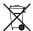
The first package to be opened is that which bears the wording "PLEASE OPEN THIS BOX FIRST". The side to be opened is that upon which the wording is present. The loudspeaker contained in this package is mounted on the support and transport trolley (C in Figure 1-).
Remove the accessory box on the upper casing, bearing the wording "BEFORE DOING ANYTHING ELSE, PLEASE READ THE OWNER'S MANUAL CONTAINED IN THE ACCESSORIES' BOX".
UNPACKING
1 Remove the screws securing the box's cover in place, which are located at the top of its wider sides
2 Remove the box's cover
3 Remove the box's wider sides
4 Remove the lower screws from the box's narrower sides
5 Remove the box's narrower sides
6 Remove the upper and lower casing
7 Use the large hex wrench to remove the two screws (V in Figure 1-) fastening the safety bar (B) to the support pallet (P).

Use maximum caution to avoid damaging the membrane of the lower subwoofer, which is facing downwards. The removal of the safety bar (B) could damage the membrane.
8 Remove the safety bar (B)
Keep the fastening bar for any future transport operations.
At this point the loudspeaker has been separated from the support pallet (P).
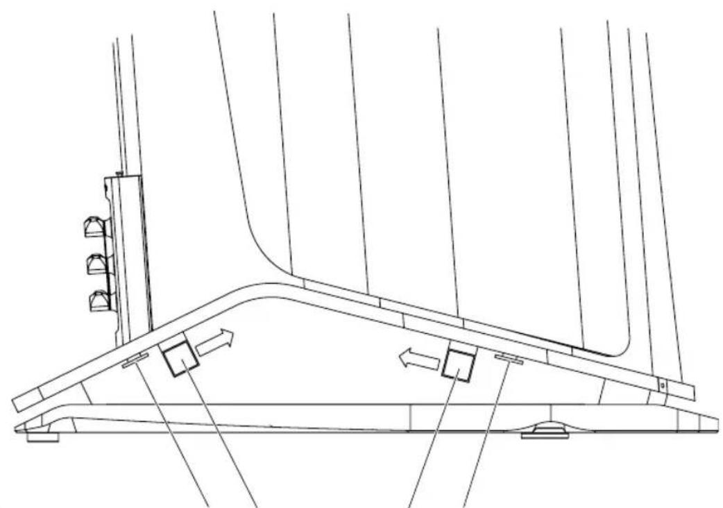
9 Pull the slides (S in Figure 2-) outward until they extend beyond the pallet and the hole (F) becomes visible. Do extract the slides beyond the hole.
10 Simultaneously turn the trolley's four cranks (R) anti-clockwise to lower the wheels to the ground

The loudspeaker could fall if tilted too much. Slowly and gradually raise the loudspeaker to the same height on all four sides to keep it in balance.
11 Once the wheels are touching the ground, extract the pallet from underneath the loudspeaker's base (Figure 3-)
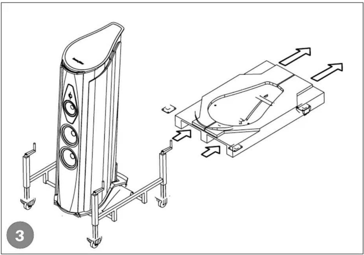
12 Screw the rear support feet with threaded pins (PS in Figure 4-) all the way into the loudspeaker's base.
13 Insert the lock nuts (G) to block the front pins in place. The raised portion should be facing upwards.
14 Apply the magnetic floor discs (M) to the rounded ends of the front support feet's pins (G).
15 Simultaneously turn the trolley's four cranks (R) clockwise to lower the loudspeaker to the floor

The loudspeaker could fall if tilted too much. Slowly and gradually lower the loudspeaker to the same height on all four sides to keep it in balance.
At this point the loudspeaker is resting on the floor, supported by the support feet, with the trolley's wheels fully raised.
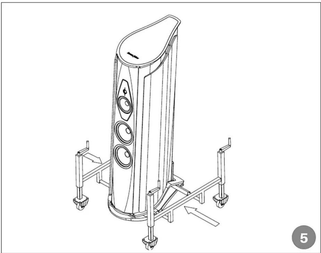
16 Push the trolley's slides (S) towards the loudspeaker until they reach the end of their stroke
The structure must be assembled in a stable manner in view of the subsequent transport operations (Figure 5-).
3.1.3 MOVING THE LOUDSPEAKER
1 Simultaneously turn the trolley's four cranks anti-clockwise to lower the wheels to the ground, and raise the loudspeaker by a few centimetres

The loudspeaker could fall if tilted too much. Slowly and gradually lower the loudspeaker to the same height on all four sides to keep it in balance.
The loudspeaker is now ready to be moved to its position within the listening environment
2 Position the loudspeaker, and turn the cranks clockwise to lower it to the ground
3.1.4 REMOVING THE HANDLING SLIDES AND THE LOAD-BEARING BARS
1 Pull the handling slides (S in Figure 6-) outwards completely to extract them from the trolley's load-bearing bars (B1 and B2)
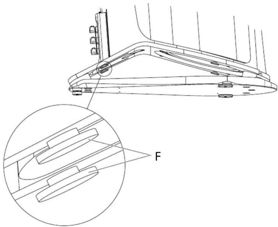
2 Carefully check the positioning of the load-bearing bars (rear B1 and front B2 in Figure 7-) and the connection system (flanges F in Figure 8-) before removing them

Use maximum caution to avoid damaging the membrane of the lower subwoofer, which is facing downwards. The removal of the load-bearing bars could damage the membrane. The removal operation must be performed by two people.
Refer to Figure 7-
3 Support the rear bar (B2) from the side, and gently move it towards the front of the loudspeaker to release it from the flange (F)
4 Support the front bar (B1) from the side, and gently move it towards the rear of the loudspeaker to release it from the flange (F)
5 Check to make sure that the loudspeaker is perfectly stable
If the front support feet need to be adjusted:
6 Use the small hex wrench (E) provided to adjust the support feet's front pins (P). Perform the operation from the upper part of the base, as shown in Figure 9-.
Unpack and position the second loudspeaker as described below.
3.1.5 MOUNTING THE HANDLING SLIDES AND THE LOAD-BEARING BARS ON THE SECOND LOUDSPEAKER
1 Open the second loudspeaker's packaging
2 Remove the accessory box on the upper casing
3 Remove the upper and lower casing
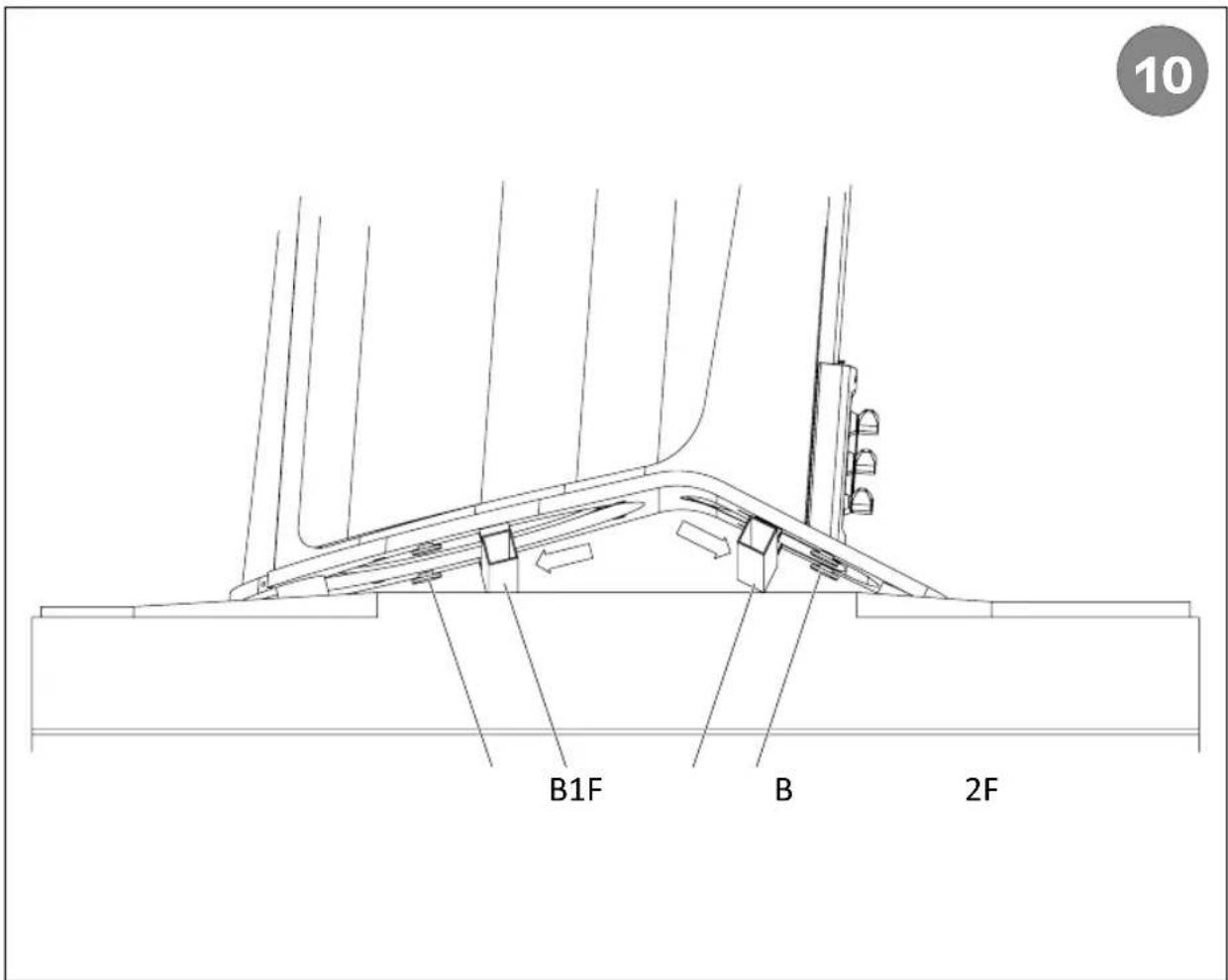
4 Check the positioning of the connection flanges (F in Figure 10-).
Insert the load-bearing bars as described below.

Use maximum caution to avoid damaging the membrane of the lower subwoofer, which is facing downwards. The insertion of the load-bearing bars could damage the membrane. The operation must be performed by two people.
1 Support the rear bar (B2 in Figure 10-) from the side, and gently move it towards the rear of the loudspeaker to release it from the flange (F)
2 Support the front bar (B1 in Figure 10-) from the side, and gently move it towards the front of the loudspeaker to release it from the flange (F)
3 Insert the handling slides (S in Figure 6-) into the trolley's load-bearing bars (B1 and B2) until the hole (F in Figure 2-) becomes visible
4 Position the second loudspeaker by repeating the same operations described for the first loudspeaker.
3.2 THE LOUDSPEAKER IN THE LISTENING ENVIRONMENT
The experience and knowledge of a qualified installer are indispensable for installing the loudspeakers within a listening environment.
3.2.1 AIDA ADJUSTMENTS
Refer to the images contained in chapter 7 Illustrations.
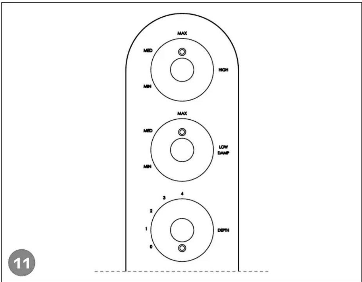
The Aida unit is comprised of a front speaker system, a rear speaker system called a Sound Field Shaper, and an infra-woofer positioned at the base of the loudspeaker. A control panel is installed at the rear, which allows for the following adjustments to be made in order to optimise the Aida unit's frequency response within the environment (Figure 11-).
| HIGH Front tweeter output level adjustment | |
| LOW DAMP | infra woofer output level adjustment |
| DEPHT Sound Field Shaper level adjustment | |
When positioning the Aida unit, the sound image must be kept as focused as possible, like for a conventional loudspeaker. Set the LOW DAMP and HIGH adjustments to the MED position, and the DEPTH regulator to the OFF position.
The Aida unit's rear speakers are mounted on the rear of the loudspeaker, oriented on one side. In this manner their output can be directed inward or outward with respect to the lateral walls of the environment.
Greater sound definition can be obtained with the rear speakers oriented inward. A sound definition with greater amplitude can be obtained with the rear speakers oriented outward, but with a slight loss of focus. This solution requires a space of at least 2 metres between each loudspeaker and the side wall.
3.2.2 LOUDSPEAKER POSITIONING
The choice of the listening environment and the loudspeakers' positioning can affect the entire audio system's performance. Rooms with irregular shapes are preferable, as these types of rooms can improve the frequency response within the listening environment, as they limit the formation of standing waves.
Within reason, the presence of rugs and curtains can have a positive effect upon the acoustic response, as they help to absorb the reflections and standing waves generated within the listening environment.
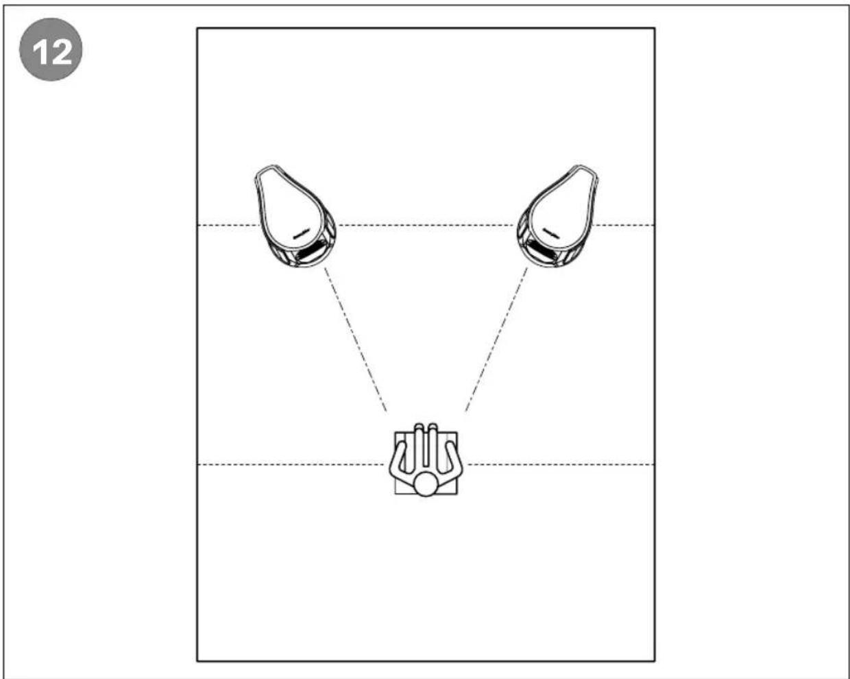
There are no fixed and universally-applicable rules for every environment. Nevertheless, one good approach to positioning the loudspeakers within the listening environment is to start by dividing the listening environment's floor plan into three equal areas, as indicated by the dotted lines in Figure 12-.
At this point, it is recommended to position the loudspeakers on the first line (A), at a good distance from the lateral walls, and to position the listening point on the second line (B).
In this manner, a good amount of air will be present all around the subjects involved in the stereo reproduction, thus allowing the loudspeakers to work freely, while at the same time shielding the listener from the acoustic reflections generated near the walls and in the corners of the room itself.
Figure 12- shows how the loudspeakers' axis should converge toward the listening position by crossing over top of it, thus creating the classic "isosceles triangle" configuration. This measure, which consists of orienting the loudspeakers in such a way as to literally point them towards the listener's ears, provides for a significant improvement in the focus of the stereophonic image.
Given that the illustrated procedure, which is aimed at creating quasi-ideal listening conditions, cannot be applied by all of our customers due to objective problems linked to the organisation of the living environment, it is recommended to position each of the two loudspeakers at a distance of at least 2 metres from one another, from the walls, from the listening point.
The listening point should be at a height of approximately 1.1 metres off the ground.
The distance between the loudspeakers themselves, and between the loudspeakers and the listening point, can be subsequently adjusted as desired.
3.2.3 AMPLIFICATION
For loudspeakers like the Aida model, adequate quality amplification is essential, regardless of the technology utilised (valves or solid state). Given the size of the loudspeakers and the environment in which they will be installed, the amplification must have a generous amount of undistorted power.
3.3 CONNECTIONS
Refer to the images contained in chapter 7 Illustrations.
After the loudspeakers have been properly positioned, their connections must be completed.
The rear panel of the Aida unit has 3 pairs of connection terminals for powering the individual loudspeakers separately:
| MID HIGH Connecting the front and rear tweeters (high and mid-high frequencies) | |
| LOW Connecting the front woofers (low frequencies) | |
| DEEP LOW Connecting the infra-woofer (deep low frequencies) |
The terminals allow for connections using cables with spade terminals, stripped cable, or banana plugs.
The loudspeakers' terminals are equipped with jumpers, which allow the loudspeakers to be connected as follows. It may be necessary to move the jumpers based on the selected connection type.
The connection methods are listed in ascending order based on the playback quality that can be obtained in terms of definition, control, and detail

The connections must be made with the equipment turned off!
The proper tightening and periodic inspection of the terminals can help to improve performance.
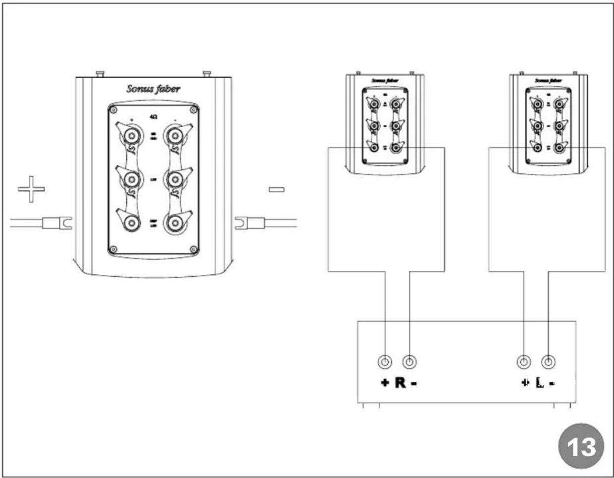
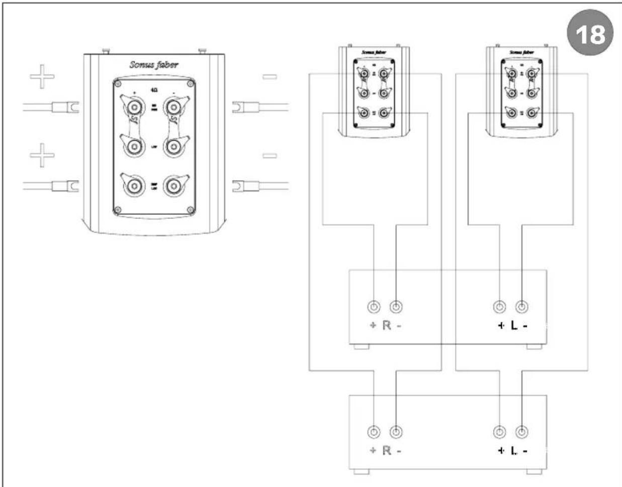
3.3.1 STANDARD CONNECTION
Use a single stereo amplifier or two mono amplifiers and a pair of power cables. Complete the connections as indicated in Figure 13-.
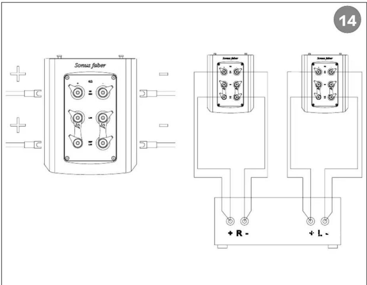
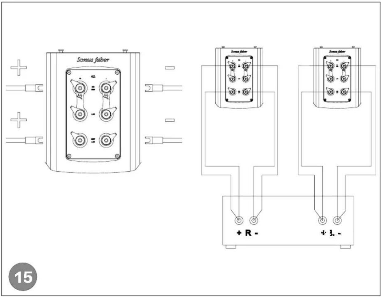
3.3.2 BI-WIRING
Use a single stereo amplifier or two mono amplifiers and two pairs of power cables.
Method A (Figure 14-, recommended method)
Connect the first pair of cables to the front and rear high/mid-high (HIGH) section, and the second pair of cables to the LOW and DEEP LOW sections.
Method B (Figure 15-)
Connect the first pair of cables to the front and rear high/mid-high (HIGH) and low frequency (LOW) sections, and the second pair of cables to the DEEP LOW sections.
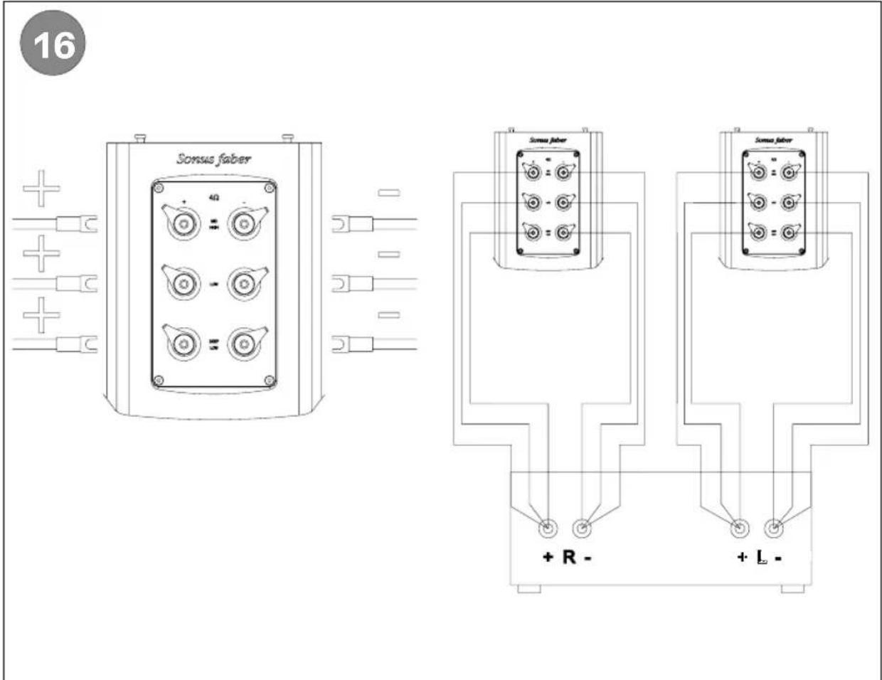
3.3.3 TRI-WIRING
Use a single stereo amplifier or two mono amplifiers and three pairs of power cables.
Complete the connections as indicated in Figure 16-.
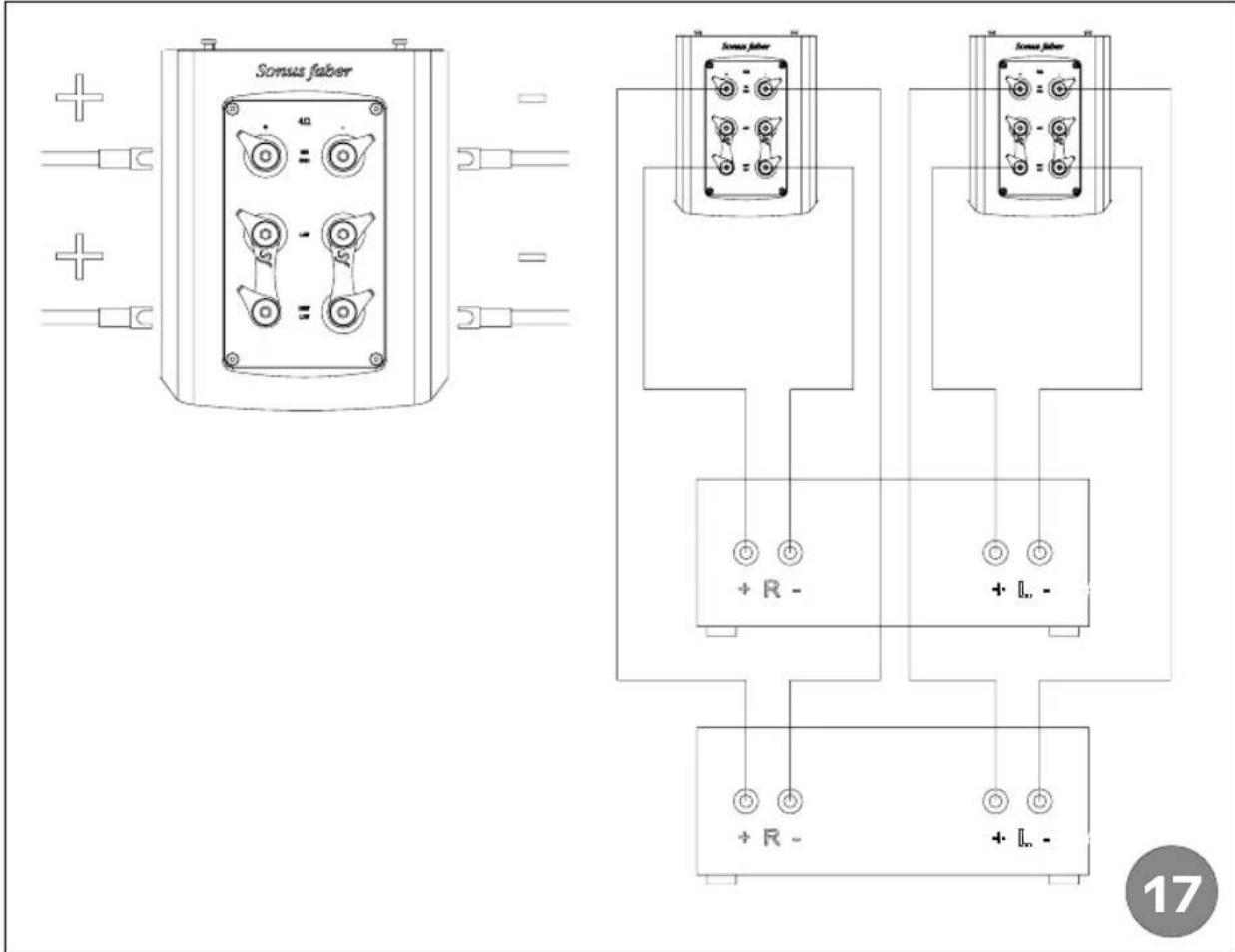
3.3.4 BI-AMPING
Use two stereo amplifiers or four mono amplifiers (of the same brand and model, if possible) and two pairs of power cables.
Method A (Figure 17-, recommended method)
Connect the first pair of cables to the front and rear high/mid-high (HIGH) sections, and the second pair of cables to the LOW and DEEP LOW sections.
Connect the first pair of cables to the front and rear high/mid-high (HIGH) and low frequency (LOW) sections, and the second pair of cables to the DEEP LOW sections.
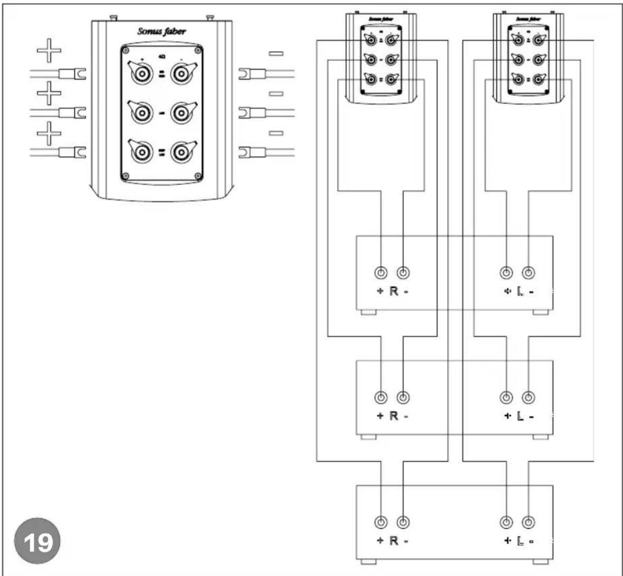
3.3.5 TRI-AMPING
Use three stereo amplifiers or six mono amplifiers (of the same brand and model, if possible) and three pairs of power cables.
Complete the connections as indicated in Figure 19-.
3.3.6 SOUND FIELD SHAPER OPTIMISATION
In order to ensure the Sound Field Shaper's proper functionality, the loudspeakers must be positioned at a minimum distance of 1-1.5 m from the rear wall. The best results are obtained with a minimum distance of 2 m from the rear wall.
Once you think that the Aida unit has been positioned in an optimal manner within the environment, the Sound Field Shaper can be adjusted. Use the DEPTH regulator (Figure 11-).
Listen to the same music track multiple times, selecting different regulator positions. Return to the "0" position after listening to the track each time in order to ascertain the differences obtained with the various adjustments.
This will allow you to obtain the best possible level of naturalness and realism for the sound within the specific environment.
3.3.7 OPTIMISATION OF THE LOW AND HIGH FREQUENCY LEVELS
The adjustments can be made using the LOW DAMP and HIGH regulators on the loudspeakers' rear panels (Figure 11-).
LOW DAMP. The amount of ultra-low frequency damping is modified. An increased level of damping corresponds to a decreased amount of ultra-low frequencies. The adjustment must be made based on the absorption capacity and the ultra-low frequency output regularity of the listening environment.
HIGH. Modifies the output of the mid-high frequencies. The MIN setting is recommended for particularly reflective environments. The MAX setting is preferable for particularly absorbent environments. The MAX adjustment is only recommended in the case of extremely absorbent environments or a considerable distance between the loudspeakers and the listening point, indicatively greater than 3.5 m.

WARNING: A "set up" that has been contemporaneously optimised to high levels in terms of DEPTH, LOW DAMP and HIGH (e.g. each knob set to maximum) will result in a decrease in the Aida unit's overall impedance. In turn, this will result in the need to use cables with suitable characteristics for the connection to the amplifier (Low resistance per linear metre and low inductance per linear metre).
4 MAINTENANCE AND CLEANING
The Aida unit only requires periodic general cleaning. In order to preserve the loudspeakers' finish, cover them with the supplied fabric protector, above all if the loudspeakers are not expected to be used for an extended period of time.

Risk of damage to the device's cabinet!
Do not use cleaning products, furniture wax, liquid detergents, or alcohol. Do not use rough cloths.
Do not use products like waxes or detergents to clean the wood portion of the cabinet, as these could stain or damage the wood or the loudspeakers themselves. Use a soft cloth (e.g. microfibre, like that supplied), and moisten it slightly with the supplied liquid, if necessary.
Wood is a natural living material that can be affected by the environmental conditions. We recommend keeping the loudspeakers away from heat sources or windows, above all during the summer months. Avoid exposing the loudspeakers to direct sunlight.
In order to clean the metal and glass surfaces of the Aida unit, it is recommended to use the liquid and cloth provided.
Use a soft brush to eliminate any dust that may have accumulated on the cabinet, the front panels, and the loudspeakers themselves, taking care not to damage the loudspeakers' delicate membranes.
These measures will help to keep the loudspeakers' working perfectly for years to come. Over time (from 100 to 300 hours of operation, based on the musical genre and the volume level), the sound will tend to improve as the speakers' moving parts (membranes and suspensions) are broken in, and the acoustic chamber will become increasingly responsive the more it is used - much like what happens with acoustic string instruments!
5 DISPOSAL
Disposal of the electrical and electronic equipment. Directives RAEE 2012/19/UE - RoHS 2011/65/UE
The crossed-out waste bin symbol shown on the equipment indicates that the product must be disposed of separately from household waste at the end of its service life.
The user is responsible for bringing the equipment to an appropriate waste collection facility at the end of its service life.
The separate disposal of the decommissioned equipment for recycling, treatment and disposal in compliance with the current environmental protection regulations will help prevent potential negative consequences for the environment and human health, and will allow for the recycling of the materials and components of which the product is comprised.
For more detailed information regarding the collection systems available in your area, please contact your local waste disposal service or the shop/dealer where you purchased the product.
This device contains materials that can pollute the environment if disposed of improperly.
The device must be disposed of at a designated sorted waste collection facility.
1 ALLGEMEINE INFORMATIONEN
1.1 BENUTZERINFORMATIONEN
Verehrter Kunde,
1.3 DÉCLARATION DE CONFORMITÉ

| SYSTEM | "3 and 2/3" way, "Sound field Shaper technology", "Zero Vibration Transmission" technology, para-aperiodic vented box "Stealth Ultraflex" system and staggered low frequency floor standing loudspeaker system. |
| TWEETER | Sonus faber "Arrow Point" DAD (Damped Apex Dome, synthesis of the classic dome and ring transducer) H28 XTR-04. A Sonus faber designed 28 mm moving coil driver, with Sonus faber's vibration optimized mechanical interface. The ultra-dynamic linearity is given by the Neodymium motor system. Implemented with a natural wood acoustic labyrinth rear chamber, a mechanical anti-resonator designed for this application. |
| MIDRANGE | Sonus faber M18 XTR-04. A Sonus faber designed 180 mm Neodymium magnet system ultra-dynamic linearity midrange. CCAW wire is used on a composite former "eddy current free" voice coil. The dynamically linear magnetic field motor incorporates triple Kellog/Goeller rings. A special custom diaphragm is made with a real time air dried non pressed blend of traditional cellulose pulp, Kapok, Kenaf and other natural fibers, developed according to the most natural sound. To further inhibit any residual cone coloration we are using a transparent viscous surface damping coating. The basket is thoroughly optimized to eliminate any resonance, fully CNC machined from solid billets of Avional and Gunmetal. The combination of the two different metals allows eliminating any mutual resonance. The same way as the tweeter, the midrange is decoupled from the main baffle board and designed synergistically with its optimized "acoustic chamber". A special coaxial anti-compressor is used, designed to remove cavity resonances and distortions. |
| WOOFERS | Sonus faber W22XTR-12. A pair of Sonus faber designed 220 mm Neodymium magnet system woofers, lightweight "sandwich" cone structure (high-tech syntactic foam core and two external surface skins of cellulose pulp) woofers. Each of them is integrated in its own acoustically amorphous "stealth reflex" chamber. Designed to blend perfectly with the special midrange and, at the same time, to have absolute definition in their range: the sandwich structure with outer paper pulp skins has the same sonic character of the midrange cone. A powerful long stroke motor system with a 2" controlled "eddy current" voice coil is implemented for high speed, performance and linearity. |
| INFRA WOOFER | Sonus faber SW32XTR-08. A Sonus faber designed 320 mm Neodymium magnet system infra woofer, sandwich cone structure with high-tech syntactic foam core and two external surface skins in Nano Carbon Fiber for maximum rigidity and light weight. An impressive 4" voice-coil, inside and outside winding design to take advantage of the magnet field strength and to control the Lorentz currents proportionally to the excursion obtaining this way the tightest available lows. To perfectly match the low-end performance to different listening rooms it is possible to adapt the SPL of the infra woofer. |
| SOUND FIELD SHAPER TWEETER | Sonus faber "Arrow Point" DAD 29XTR2. A Sonus faber designed 29 mm moving coil driver. The ultra-dynamic linearity is given by the new Neodymium motor system. |
| SOUND FIELD SHAPER MIDRANGES | Sonus faber M8XTR. A pair of Sonus faber designed 80 mm ultra-dynamic linearity midrange. CCAW wire is used on a controlled "eddy current free" voice coil. The dynamically linear magnetic field motor has focused field geometry. A special custom diaphragm is made with a blend of traditional cellulose pulp, Kapok, Kenaf and other natural fibers. A special coaxial anti-compressor is used, designed to remove cavity resonance and distortions. |
| CROSS-OVER FREQUENCIES | 55 Hz - 150 Hz - 200 Hz - 3000 Hz |
| FREQUENCY RESPONSE | 18 Hz - 35.000 Hz, Stealth Ultraflex included |
| SENSITIVITY | 92 db SPL (2.83 V/1 m). |
| NOMINAL IMPEDANCE | 4 Ω. |
| POWER HANDLING | 100W - 1KW, without clipping |
| DIMENSIONS (HxWxD) | 1725 x 482 x 780 mm. |
| WEIGHT | 330 Kg per pair - net weight / 550 Kg per pair - shipping weight |
natural_image
Technical line drawing of a speaker tower and its internal component with directional arrows indicating motion (no text or symbols)
natural_image
Technical line drawing of a speaker tower with three speakers and directional arrows indicating sound or vibration components (no text or symbols)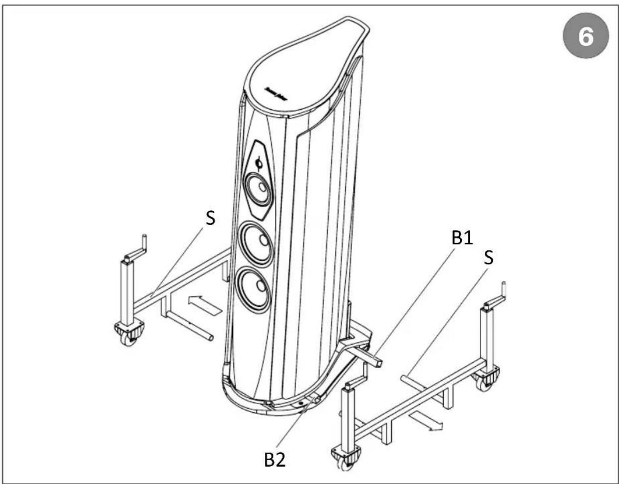
natural_image
Technical line drawing of a mechanical structure with no visible text or symbols7
B2F
F
8
natural_image
Technical line drawing of a mechanical component with an inset magnified view labeled 'F' (no text or symbols present)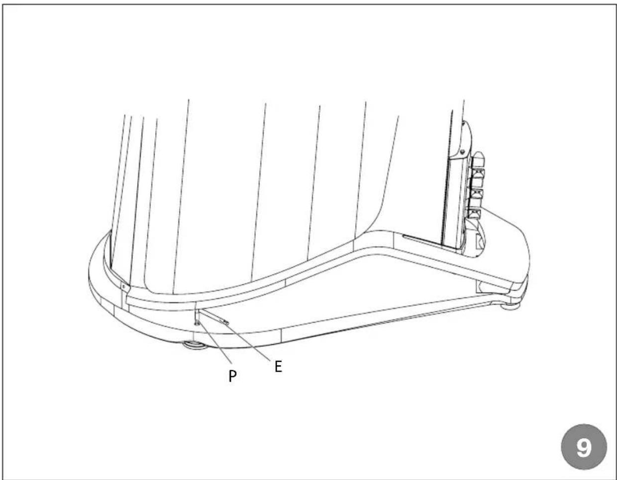
Sonus faber
sonusfaber.com


- WARRANTY AND AFTER SALES SUPPORT
- DECLARATION OF CONFORMITY
- Aida
- Directives:
- Standards:
- CEI EN 60065:2016
- CEI EN 55013:2014
- CEI EN 55020:2016
- CEI EN 61000-6-1:2013
- CEI EN 61000-6-3:2014
- SAFETY INFORMATION
- INSTALLATION
- UNPACKING
- PACKAGING CONTENTS
- SPEAKER PREPARATION
- UNPACKING
- MOVING THE LOUDSPEAKER
- REMOVING THE HANDLING SLIDES AND THE LOAD-BEARING BARS
- MOUNTING THE HANDLING SLIDES AND THE LOAD-BEARING BARS ON THE SECOND LOUDSPEAKER
- THE LOUDSPEAKER IN THE LISTENING ENVIRONMENT
- AIDA ADJUSTMENTS
- LOUDSPEAKER POSITIONING
- AMPLIFICATION
- CONNECTIONS
- STANDARD CONNECTION
- BI-WIRING
- TRI-WIRING
- BI-AMPING
- TRI-AMPING
- SOUND FIELD SHAPER OPTIMISATION
- OPTIMISATION OF THE LOW AND HIGH FREQUENCY LEVELS
- MAINTENANCE AND CLEANING
- DISPOSAL
- Disposal of the electrical and electronic equipment. Directives RAEE 2012/19/UE - RoHS 2011/65/UE
- ALLGEMEINE INFORMATIONEN
- BENUTZERINFORMATIONEN
- DÉCLARATION DE CONFORMITÉ
Brand : Sonus Faber
Model : Aida
Category : Loudspeaker