
Multidesk Comfort - Office OneConcept - Free user manual and instructions
Find the device manual for free Multidesk Comfort OneConcept in PDF.
| Product type | Electric height-adjustable desk |
| Brand | OneConcept |
| Model | Multidesk Comfort |
| Article number | 10034481, 10034483 |
| Maximum load | 100 kg |
| Adjustable frame width | 100-160 cm |
| Height adjustment range | 73-123 cm |
| Tabletop dimensions (accessory) | 120 x 65 cm |
| Tabletop weight (accessory) | 21 kg |
| Frame material | Steel |
| Tabletop material (accessory) | Melamine particle board |
| Power supply | 220-240 V ~ 50/60 Hz |
| Operating temperature | -5 °C to +40 °C |
| Display | Touch screen |
| Height memory | Up to 3 preset positions |
| Timer | Sit-stand reminder (0.5-2 h) |
| Units of measurement | Centimeters or inches |
| Safety sleep mode | Yes (manual activation) |
| Overload protection | Yes (error codes ER1, etc.) |
| Adjustable feet | Yes (for uneven floors) |
| Package contents | Frame, columns, feet, control box, cables, screws, dowels |
| Cleaning and maintenance | Disconnect before cleaning; use a dry cloth |
| Safety | Do not sit; do not use outdoors; unplug if unusual smell or noise |
| Certifications | CE, UKCA |
Frequently Asked Questions - Multidesk Comfort OneConcept
User questions about Multidesk Comfort OneConcept
0 question about this device. Answer the ones you know or ask your own.
Ask a new question about this device
Download the instructions for your Office in PDF format for free! Find your manual Multidesk Comfort - OneConcept and take your electronic device back in hand. On this page are published all the documents necessary for the use of your device. Multidesk Comfort by OneConcept.
USER MANUAL Multidesk Comfort OneConcept
Hight-adjustable Desk
Unit 6 Riverside Business Centre
Brighton Road
Shoreham-by-Sea
BN436RE
United Kingdom
Congratulations on purchasing this item. Please read the following instructions carefully and follow them to prevent possible damages. We assume no liability for damage caused by disregard of the instructions and improper use. Scan the QR code to get access to the latest user manual and more product information:

CONTENT
Technical Data 32
Safety Instructions 33
Parts Supplied 34
Assembly 36
Controller 54
Operation 54
Troubleshooting 55
Disposal Considerations 57
Declaration of Conformity 57
TECHNICAL DATA
| Item number 10034481 10034483 | ||
| Weight capacity 100 kg | ||
| Adjustable width 100-160 cm | ||
| Adjustable height range 73-123 cm | ||
| Electrical control module | ||
| Power supply 220-240 V ~ 50/60 Hz | ||
| Operating temperature range -5 °C bis +40 °C | ||
ACCESSIONS
| Item number 10034484 10034485 | ||
| Table top Dark walnut White | ||
| Material Melamine-coated chipboard | ||
| Dimensions 120 x 65 cm | ||
| Weight 21 kg | ||
NOTE: The table top is not included and must be purchased in addition to the table frame.
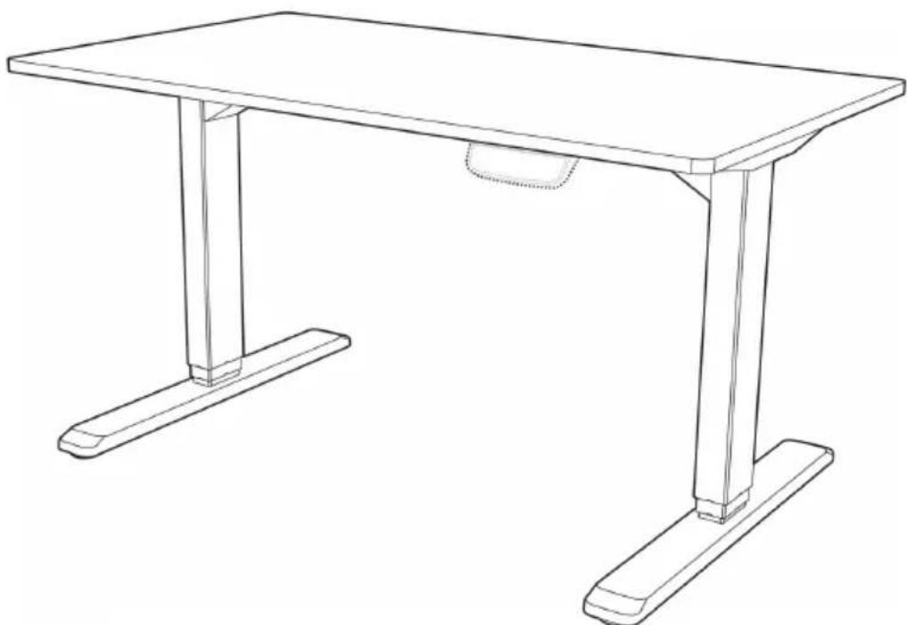
The electrically height-adjustable desk consists of a steel table frame and an electrical control module with power supply unit for height adjustment:
SAFETY INSTRUCTIONS
- Read these operating instructions completely and carefully before installation. Observe the safety and installation instructions to avoid serious injuries and serious damage to the product and its components.
- This product may be only used by children 8 years old or older and persons with limited physical, sensory and mental capabilities and / or lack of experience and knowledge, provided that they have been instructed in use of the product by a responsible person who understands the associated risks. Children shall not play with the product.
- Cleaning and user maintenance shall not be made by children without supervision. Unplug the desk when the system isn't in use, and place the power plug out of children reach.
- Never sit on the desktop and ensure that others do not sit on it to avoid serious injury.
- When adjusting the height of the desktop, make sure that there are no objects or other obstacles in the area.
- Do not leave the cords or plug unorganized in order to prevent tripping hazards.
- Any attempts to reconstruct the desk frame aren't allowed.
- Do not add anything to the adjustable junctions of the desk frame.
- Outdoor use is prohibited.
Electrical Safety Instructions
- The product is powered by electricity. In order to avoid burns, fire and electric shock, please read the instructions carefully.
- Do not clean the product with water while the power is still connected.
- Do not disassemble or replace components while the power is still connected.
- Never operate the system if it is in moist environment or its electrical components have contact with liquids.
- Disconnect the power supply and do not operate the system if the control box makes noise or odor.
- Alterations of the given power unit and control box are not allowed.
- Never use the desk if the power cord or plug is damaged. These must be replaced by the manufacturer, its service agent or similarly qualified persons.
PARTS SUPPLIED
Needed tools
- Spirit level
- Allen wrench (included)
- Drill
- Phillips screwdriver
- optional: Cordless screwdriver
Recommended material
- Shipping blanket
NOTE: Unless otherwise indicated, required tools and recommended installation material are not included in the scope of delivery.
| A (x1) Crossbar Side Bracket | B (x2) |
| C (x2) Foot Cable Management Tray | D (x1) |
| E (x2) Lifting Column Fixing Plate | F (x1) |
| G (x1) Control Box Hook | H (x2) |
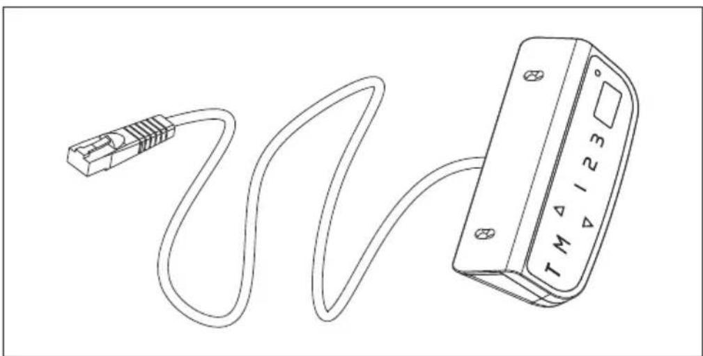
| I (x1) Power cord with mains plug Controller | J (x1) |
| S-A (x20) Hex Head Screw Phillips Head Screw + 1 Spacer | S-B (x10) |
| S-C (x2) Phillips Head Screw Phillips Head Screw | S-D (x6) |
| S-E (x3) Cable Clip Rubber Pad | S-F (x8) |
NOTE:
The picture of the controller is for your reference only. Actual product may vary.
ASSEMBLY
Preparation
Prepare a spacious area for installation, and put a shipping blanket on the area to prevent scratches on the floor and the frame.
Attaching Side Brackets
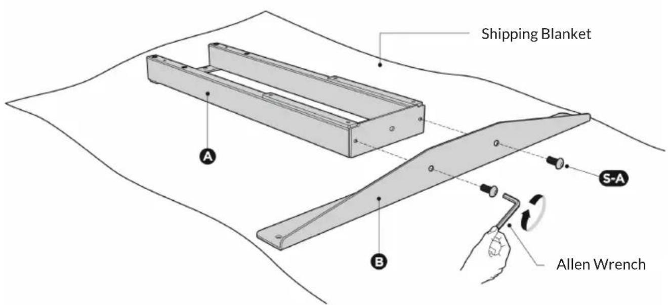
Unpack the crossbar (A) and carefully place it on the floor upside-down. Attach the side brackets (B) to the end of the crossbar (A) using the 2 screws (S-A), as shown above with the Allen wrench.
Repeat the same process to assemble the other side bracket.
NOTE: The drawings of both of the crossbar and side brackets are the backside of the components. Please make sure the crossbar and side brackets keep facing down while installation, which is convenient for the further steps.
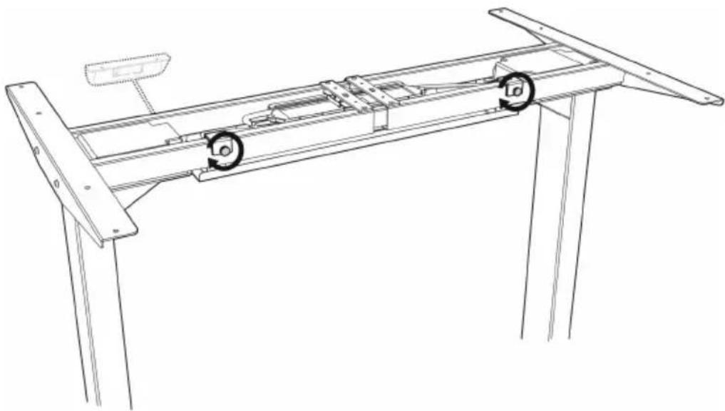
Drilling Mounting Holes
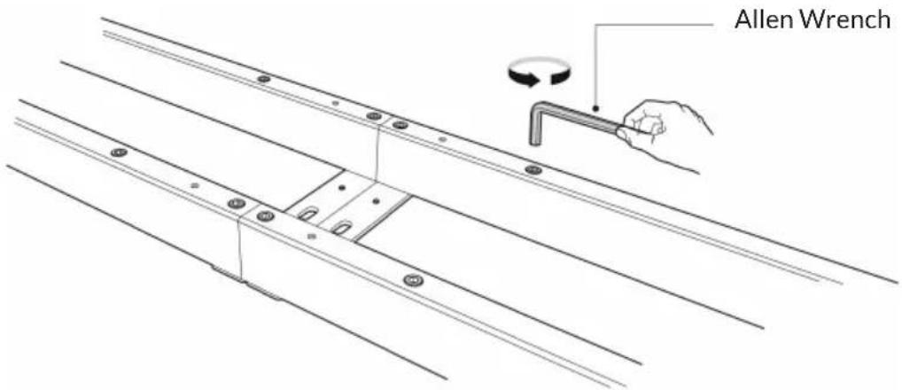
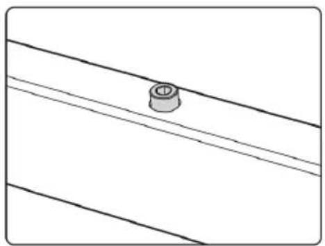
Loosen the hex head screws that fix the adjustable junction, but do not completely take out the screws.
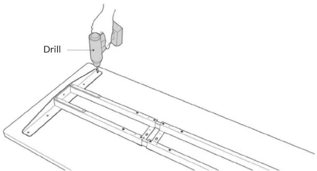
Place the assembled frame on the back of the tabletop. Ensure that the frame is placed in the center of the table.
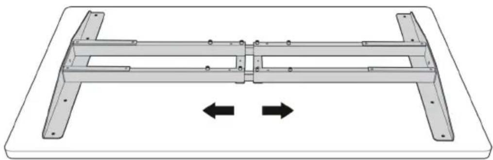
Then adjust the frame to suit the size of the tabletop.
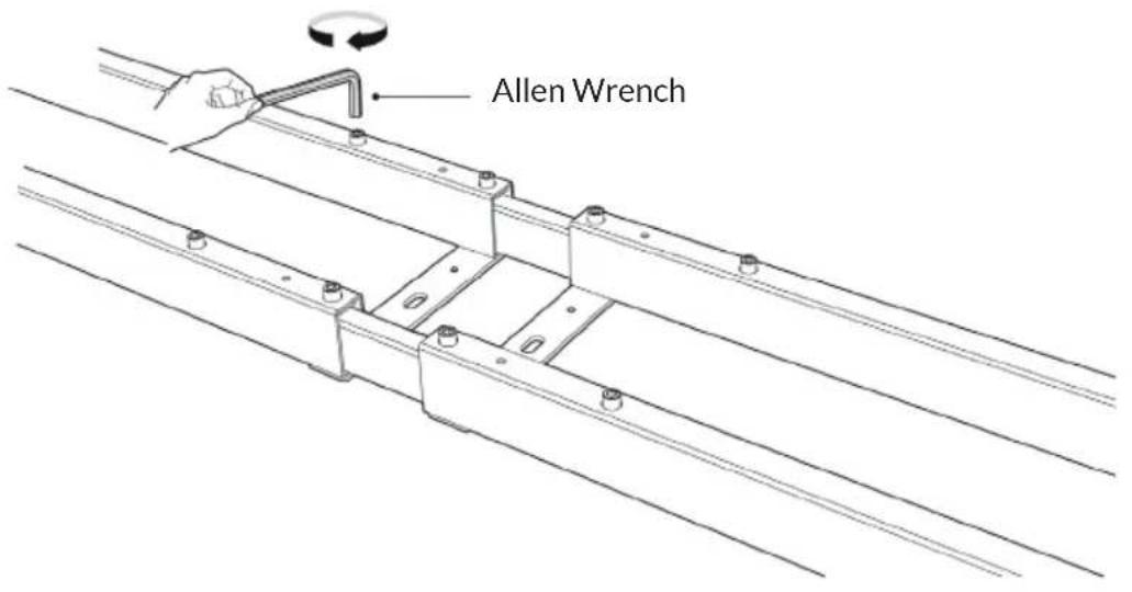
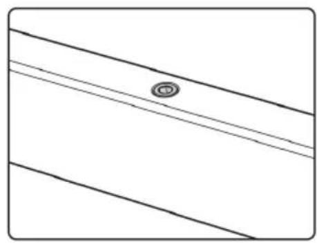
Retighten all the hex head screws to finish the adjustment.
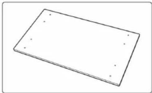
After tightening the screws, use a drill to make mounting holes on the backside of the tabletop through the 8 mounting holes on the side brackets.
NOTE: The depth of the mounting holes should be over 10mm and the diameter should be less than 3mm .
EN
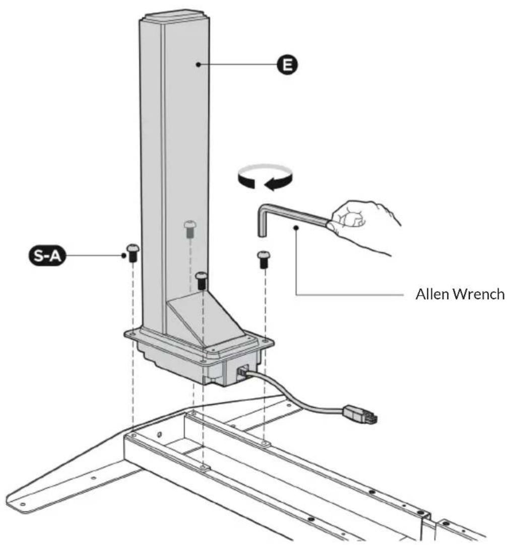
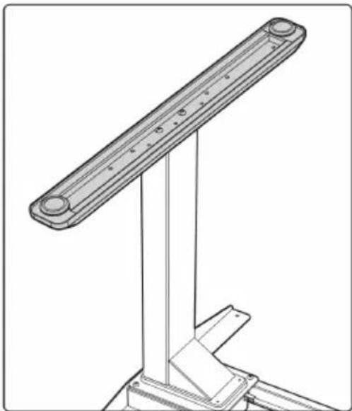
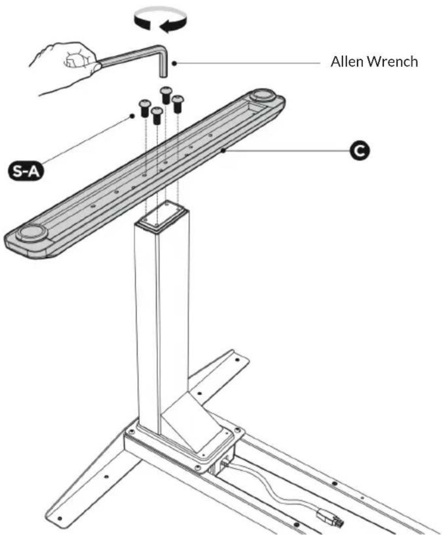
Assembling the Lifting Columns
Remove the tabletop for further installation.
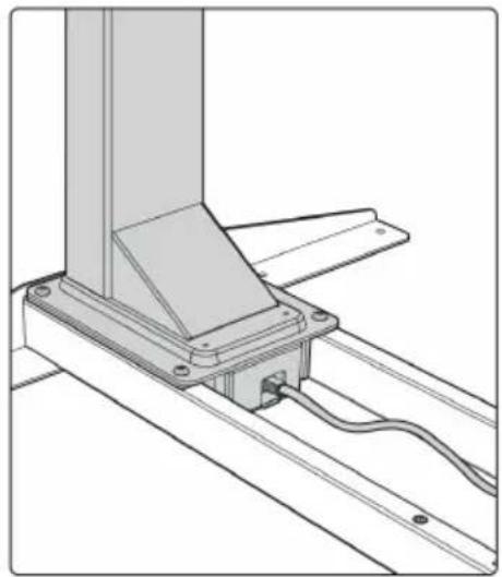
Insert one lifting column into one end of the crossbar with the head of the lifting column facing inward. Make sure the mounting holes on the lifting column completely align with the screw holes on the crossbar.
Fix the lifting column (E) with crossbar using 4 screws (S-A) with the Allen wrench.
Repeat the same process to assemble the other lifting column.
Assembling the Feet
Place the foot on the bottom of the lifting column.
Align the mounting holes on the foot with the screw holes on the lifting column.
Fix the foot (C) using 4 screws (A), with the Allen wrench.
Repeat the same process to assemble the other foot.
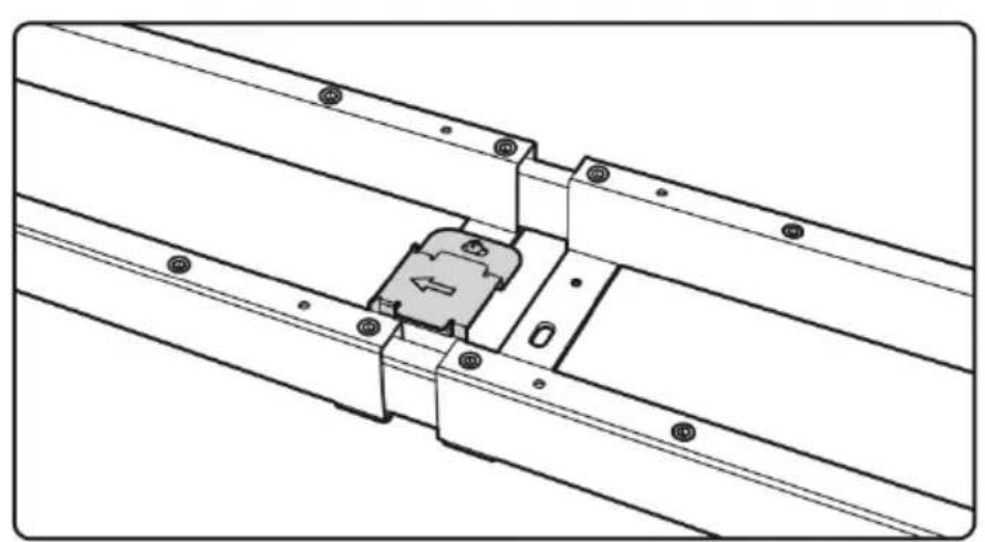
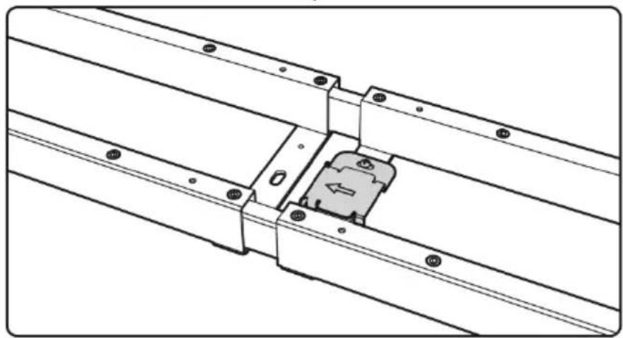
Assembling the Fixing Plate
Align the mounting holes on the fixing plate with the screw holes as shown.
Attach the fixing plate (F) on the center of the crossbar with 2 screws (S-D) using a Phillips screwdriver.
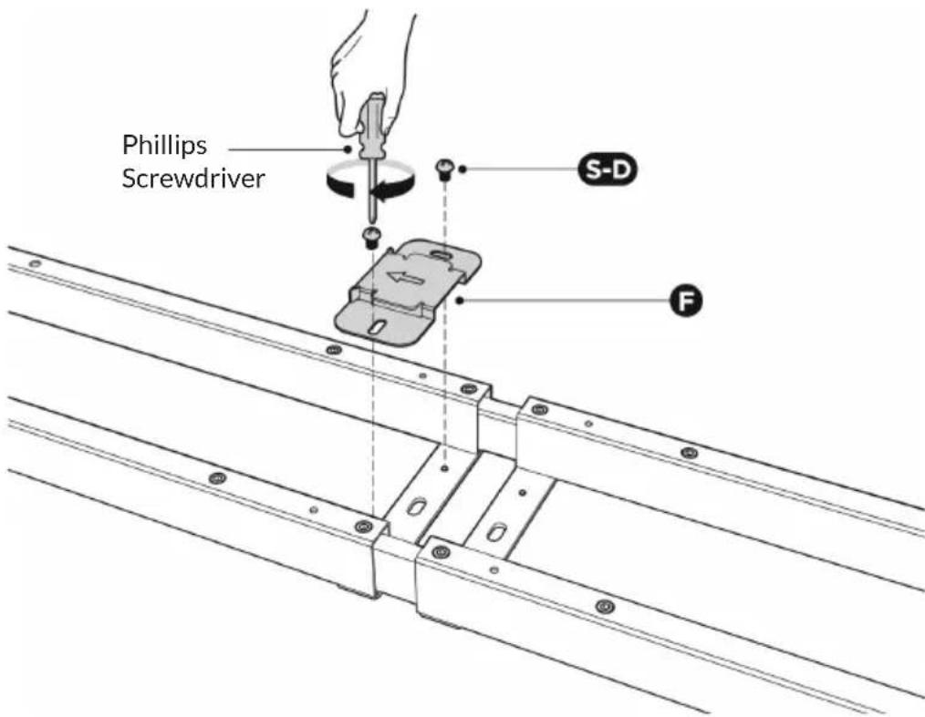
NOTE: The arrow on the fixing plate indicates the direction of sliding in the control box. Follow the direction of the arrow to mount the control box in the next step.
The fixing plate can be attached to either of the right side and the left side.

EN
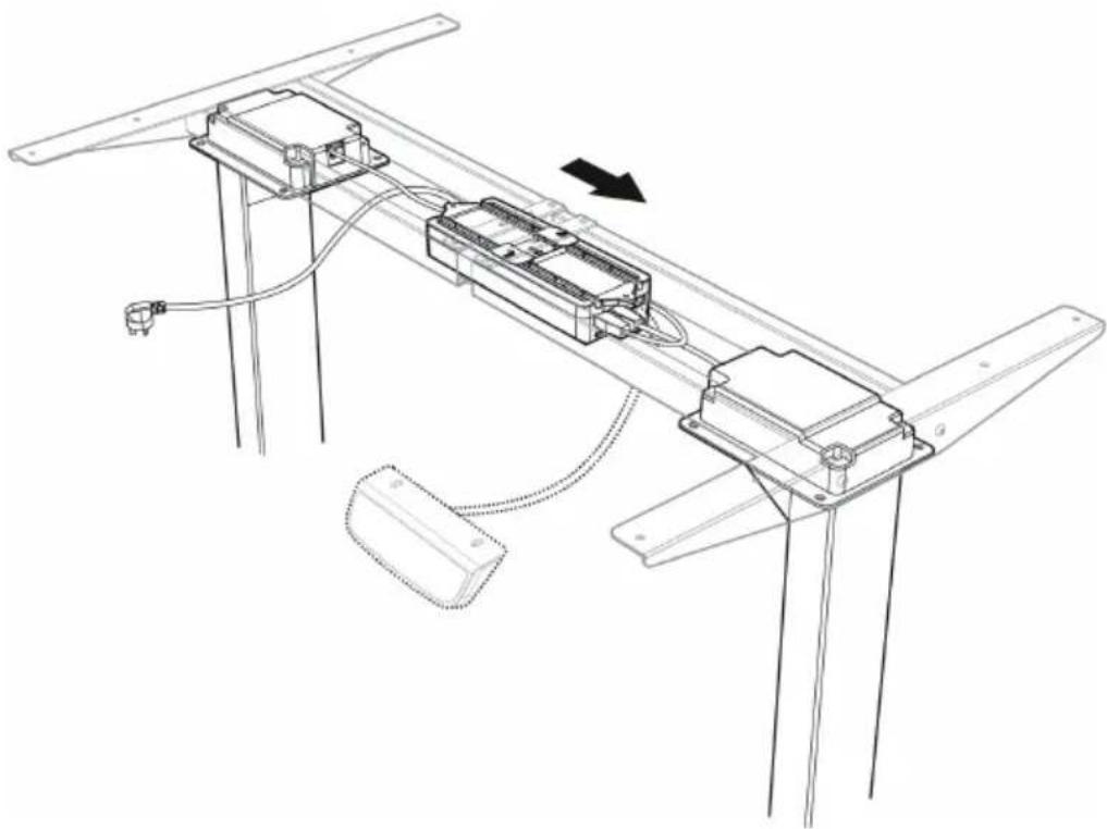
Connecting Cords and Attaching the Control Box
Turn over the desk frame with the crossbar facing up.

CAUTION
Risk of injury! At least two persons are required to turn the desk frame. If only one person turns over the desk frame, serious bodily injuries might occur.
Connect the two motor cords to the two ports on the right marked "M1" and "M2".
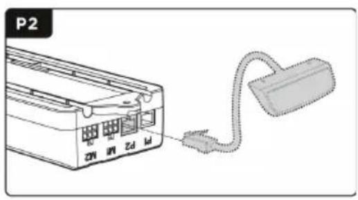
Connect the controller (J) cord to the port marked "P2" on the right.
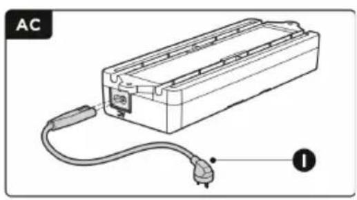
Insert the power plug (I) on the port on the left.
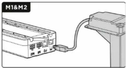
NOTE: Please make sure the slot on the control box (G) is facing upward. There is no corresponding relation between the two motor ports and the two lifting columns.
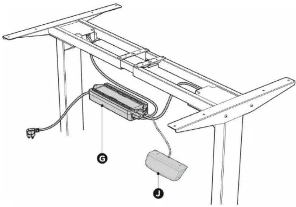
NOTE: The picture of the controller is for your reference only. Actual product may vary.
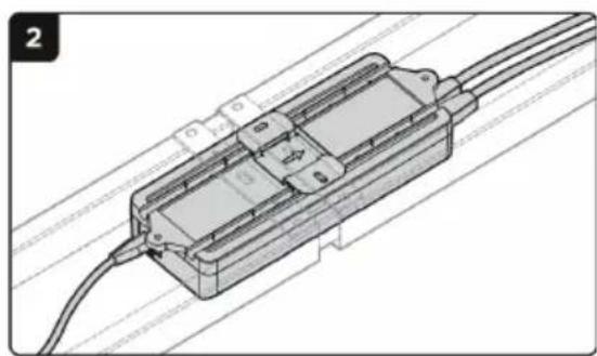
Align the fixing plate with the right end of the control box's slot.
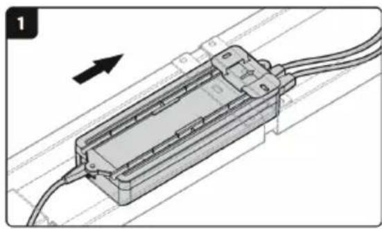
Slide the control box into the fixing plate from the left until the control box cannot be moved.
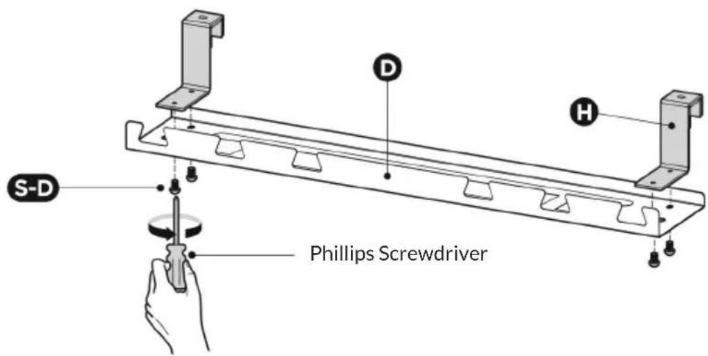
Assembling the Cable Management Tray
Align the mounting holes on the tray hangers with the screw holes on the cable management tray. Assemble the tray hangers to the cable management tray (D) with 4 screws (S-D) from below using a Phillips screwdriver.
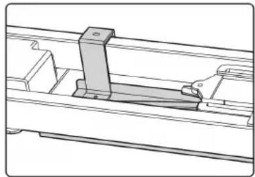
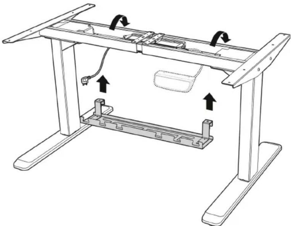
Hang the cable management tray on the crossbar as shown in the two drawings (right and below).
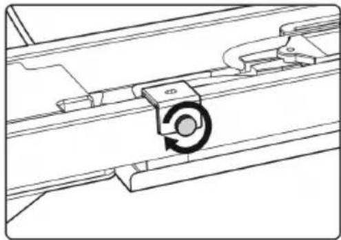
Tighten the knobs on the tray hangers.
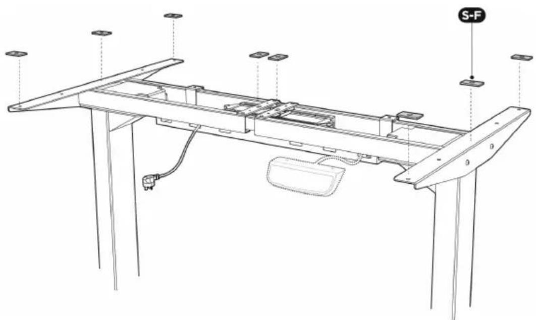
Assembling the Desktop
EN
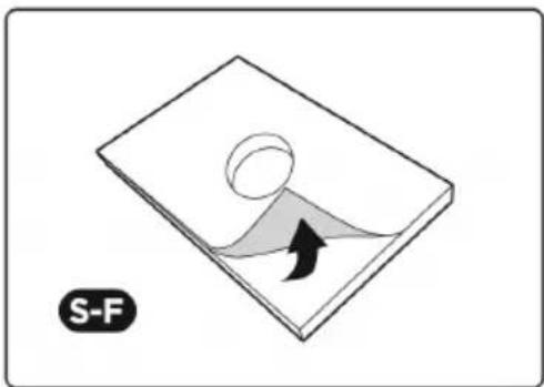
Remove the backings of the adhesive rubber pads (S-F). Stick them to the surface of the crossbar on the eight positions as shown.
Align the previously drilled screw holes with the mounting holes on the crossbar. Insert the 4 screws (S-B) from below and tighten them.
Repeat to mount the desktop on the other side.
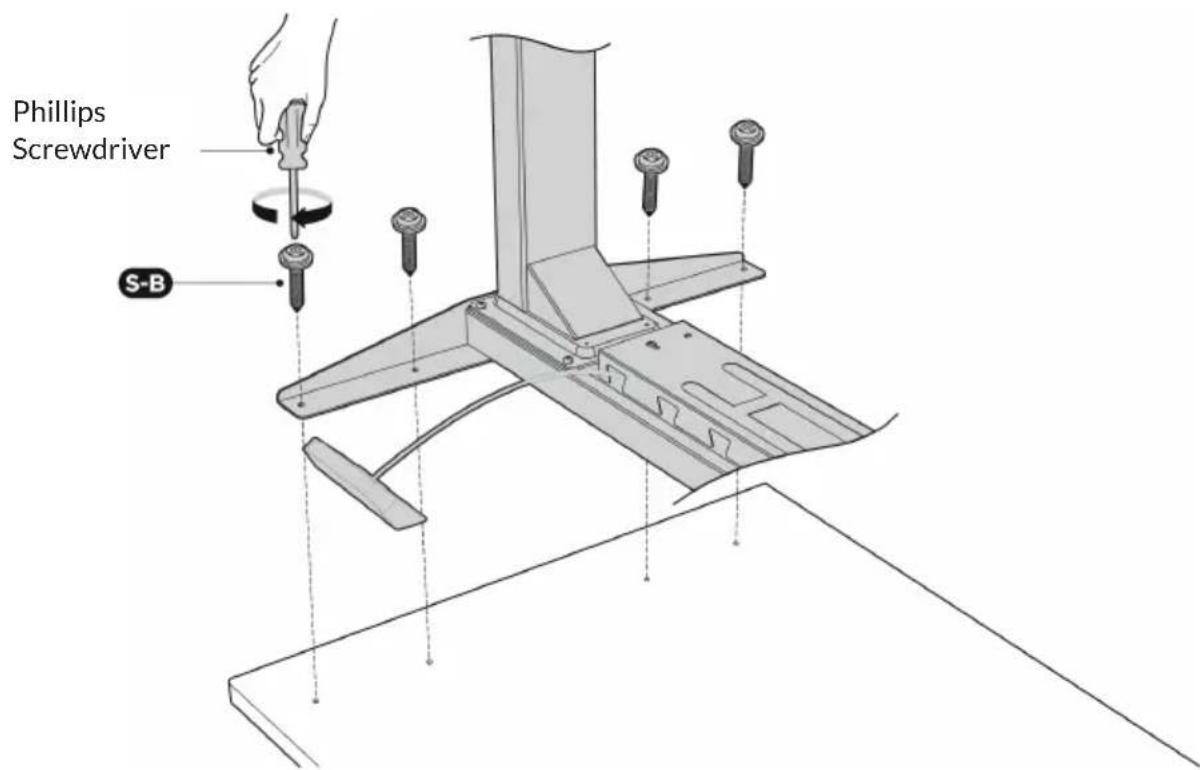
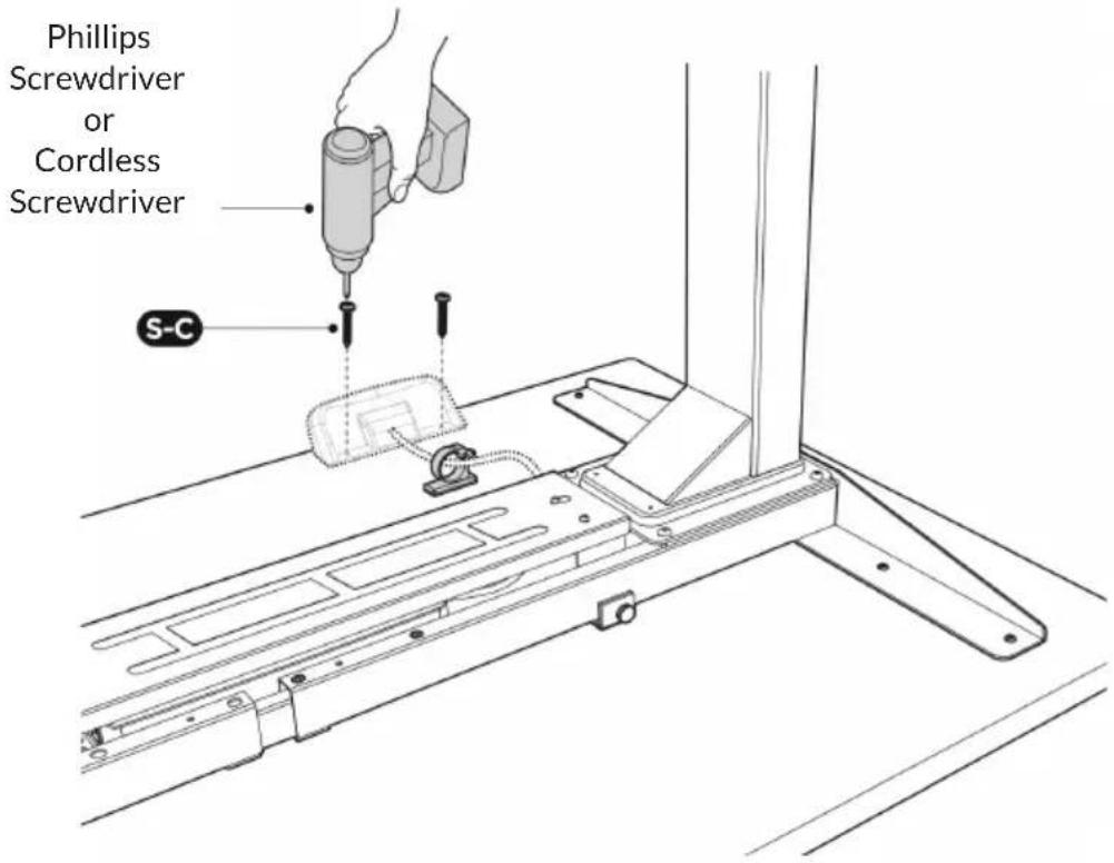
Attach the controller to the desktop with 2 screws (S-C).
Use a Phillips screwdriver or (if available) a cordless screwdriver.
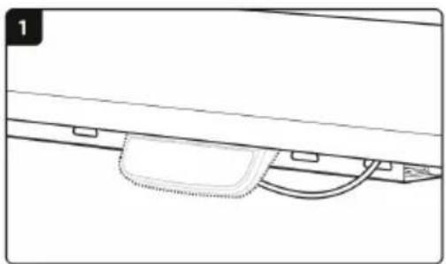
Stick the adhesive cable clip (S-E) to the desktop from below to organize the cords.
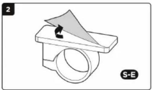
Low Profile Adjustment
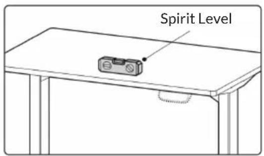
Two adjustable feet are located under each table foot. If the floor is uneven, simply rotate the leveling foot to adjust the height so that the desk is stable.
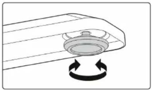
TIP: Use a spirit level to check if the desktop is even.
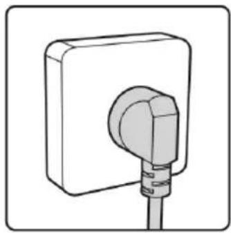
Insert the plug into the socket.
The desk is now fully assembled and ready for use.
CONTROLLER
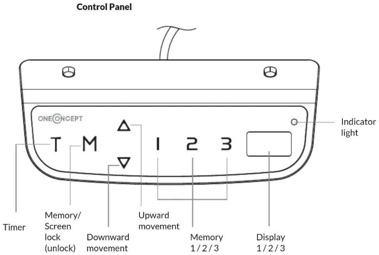
OPERATION
Activate the System: Touch the screen. The "---" will appear on the display. Then, press and hold the "M" button for 3 seconds. The current height will display, and you can start operating the system.
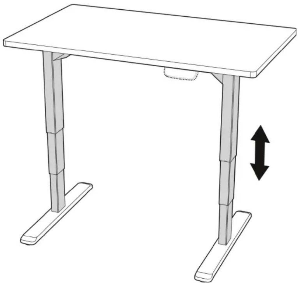
Height Adjustment: Press and hold the up button to lift the desk. Press and hold the down button to lower the desk.
Timer: The timer is designed to inform users to stand up after a set period of time. Press the "T" button to set the period of time. The display will flash "0.5 h" for 0.5 hour. Each press of the "T" button leads to a 0.5 hour increment. The maximal setting of time is 2 hours. When the display stops flashing, then the period of time is successfully set. And the indicator light on the top right of panel will be on. When the set time is up, the buzzer will beep to remind the users. The timer will turn off automatically after a long beep. To cancel the timing, press "T" button for 5 times until the display shows the current height and the indicator light is off.
Memory Selling: Adjust the desk to your desired position. Press the "M" button, then "S-" appears on the display. Press "1", "2" or "3".
The memory is successfully set. You can store up to 3 heights by repeating the same process.
Protective Standby Mode: If there is no operation for 1 minute, the system will enter the protective standby mode. To turn off the standby mode, press and hold the "M" button for 3 seconds. You can also press and hold the "M" button for 3 seconds to activate the standby mode, when you don't need to operate the system.
Power-saving mode: When no actions are made for over 10 minutes, the system will enter power-saving mode. Press any buttons to enter operation mode.
Measurement Switch (cm/inch): Press "T" for 8 s. The buzzer will beep twice. The measurement is changed from centimeter to inch. If you want to switch the measurement back to centimeter, also press the "T" for 8 s.
Reset Mode: While the system is reconnected, press the down button until "RST" is displayed. Continue to press the button. The desk will move down and then raise a little bit. (Make sure you never release the button during the process.) After the movement stops, the system is successfully reset to the starting position.
TROUBLESHOOTING
This repair guide intends to help you identify and solve the minor problems caused by unusual operation of the electric system of our sit-stand desk. The simple procedures in this manual are easy to follow and capable of solving the most problems happened in everyday use.
If "ER1/ER2/HOT/ER3/ER4/ER5" appear on the control panel, this is normally nothing to worry about, and usually is an indication that the system has experienced activity that is above rated specifications. Simply follow the steps below, most errors can be solved. If the problems aren't solved, please contact your point of purchase to replace components.
Error codes on the display
| Error code Steps | |
| ER1 | 1. Check if the desk is overloaded. If so,remove the items on the desktop, and disconnect the power. If not, only disconnect the power. 2. Wait for 10 s then reconnect the cord. |
| ER2/HOT | The system has experienced above-normal temperature. So, allow your desk to cool down and remain idle for approximately 20 minutes. Never turn off the power during the process. |
| ER3/ER4/ER5 | 1. The system has experienced unusual electrical problems. Firstly, disconnect the motor cords and power. 2. Wait for 10 s then reconnect the cords. 3. Press and hold the down button until the image appears, and continue to press the button. The desk will move down and then raise a little bit. (Make sure you never release the button during the process.) 4. Release the button after the movement stops. |
Control panel problems
If the control panel does not respond or you cannot adjust the desk, contact customer service. First, check that the desk is properly connected to the power supply.
The lifting columns are not working.
If the desk does not work, after confirming the control panel works properly, please turn the power off, and restart the system. If it still does not work, contact customer service.
Overcurrent protection
In addition, an over-current protection mode has been also programmed in this system. When the electricity is over rated specification, the system will enter this mode. The desk will lower approximately 30mm and stop with the height displayed if the mode activates. This is only an introduction of the function of the downward movement. No trouble shooting is required when this happens.
DISPOSAL CONSIDERATIONS

If there is a legal regulation for the disposal of electrical and electronic devices in your country, this symbol on the product or on the packaging indicates that this product must not be disposed of with household waste. Instead, it must be taken to a collection point for the recycling of electrical and electronic equipment. By disposing of it in accordance with the rules, you are protecting the environment and the health of your fellow human beings from negative consequences. For information about the recycling and disposal of this product, please contact your local authority or your household waste disposal service.
DECLARATION OF CONFORMITY
CE UK CA
Manufacturer:
Chal-Tec GmbH, Wallstrasse 16, 10179 Berlin,
Germany.
Importer for Great Britain:
Chal-Tec UK limited
Unit 6 Riverside Business Centre
Brighton Road
Shoreham-by-Sea
BN436RE
United Kingdom
The complete declaration of conformity of the manufacturer can be found at the following link: https://use.berlin/10034480
Chere cliente, cher client,
Unit 6 Riverside Business Centre
Brighton Road
Shoreham-by-Sea
BN436RE
United Kingdom
Unit 6 Riverside Business Centre
Brighton Road
Shoreham-by-Sea
BN436RE
United Kingdom
Chal-Tec GmbH, Wallstraße 16, 10179 Berlin, Germany.
Unit 6 Riverside Business Centre
Brighton Road
Shoreham-by-Sea
BN436RE
United Kingdom