J208D17 - Milling machine JONSERED - Free user manual and instructions
Find the device manual for free J208D17 JONSERED in PDF.
| Product Type | Tiller (power tiller) |
| Brand | Jonsered |
| Model | J208D17 |
| Fuel | Unleaded gasoline (max 10% ethanol E10) |
| Fuel Tank Capacity | 3.2 pints (approx. 3.0 L) |
| Engine Oil Type | SAE 30 (above 0°C) or 5W-30 (below 0°C) |
| Engine Oil Capacity | 20 oz (approx. 0.59 L) |
| Spark Plug | Champion R12YC (gap 0.030 in / 0.76 mm) |
| Tire Pressure | 1.4 kg/cm² (20 PSI) |
| Working Width | 17 inches (43 cm) - estimated based on model |
| Tilling Depth | Adjustable from 1 to 6 inches (2.5 to 15 cm) |
| Main Functions | Tilling, cultivating, transport, forward/reverse |
| Speeds | Multiple positions (tilling, forward, reverse, neutral) |
| Maintenance - Oil Change | Every 25 hours of use |
| Maintenance - Air Filter | Clean every 25 h, replace if necessary |
| Maintenance - Spark Plug | Replace every 50 hours |
| Safety - Engine Stop | Throttle control in STOP position, disconnect spark plug before maintenance |
| Safety - Gasoline Precautions | Never refuel with hot engine, use approved container |
| Spare Parts | Tines, belts, spark plugs, filters available |
| Repairability | Authorized Jonsered service center |
Frequently Asked Questions - J208D17 JONSERED
User questions about J208D17 JONSERED
0 question about this device. Answer the ones you know or ask your own.
Ask a new question about this device
Download the instructions for your Milling machine in PDF format for free! Find your manual J208D17 - JONSERED and take your electronic device back in hand. On this page are published all the documents necessary for the use of your device. J208D17 by JONSERED.
USER MANUAL J208D17 JONSERED
natural_image
Technical line drawing of a manual tiller machine with visible blades and housing (no text or symbols)- Read the Manual carefully. Be thoroughly familiar with the controls and the proper use of the equipment. Know how to stop the unit and disengage the controls quickly.
- Never allow children to operate the equipment. Never allow adults to operate the equipment without proper instruction.
- Keep the area of operation clear of all persons, partic u lar ly small children, and pets.
PREPARATION
- Thoroughly inspect the area where the equipment is to be used and remove all foreign objects.
- Disengage all clutches and shift into neutral before starting the engine (mo tor).
- Do not operate the equipment without wearing adequate outer garments. Wear footwear that will improve footing on slippery surfaces.
- Handle fuel with care; it is highly flammable.
- Use an approved fuel container.
- Never add fuel to a running engine or hot engine.
- Fill fuel tank outdoors with extreme care. Never fill fuel tank indoors.
- Replace gasoline cap securely and clean up spilled fuel before restarting.
- Use extension cords and receptacles as specified by the manufacturer for all units with electric drive motors or electric starting motors.
- Never attempt to make any adjustments while the engine (motor) is running (except where specifically rec om mend ed by manufacturer).
OPERATION
- Do not put hands or feet near or under rotating parts.
- Exercise extreme caution when operating on or crossing gravel drives, walks, or roads. Stay alert for hidden hazards or traffic. Do not carry pas sen gers.
- After striking a foreign object, stop the engine (motor), remove the wire from the spark plug, thoroughly in spect the tiller for any damage, and repair the damage before restarting and oper at ing the tiller.
• Exercise caution to avoid slipping or falling.
- If the unit should start to vibrate ab nor mal ly, stop the engine (motor) and check immediately for the cause. Vi bra tion is generally a warning of trouble.
- Stop the engine (motor) when leaving the operating position.
- Take all possible precautions when leaving the machine unattended. Disengage the tines, shift into neutral, and stop the engine.
- Before cleaning, repairing, or inspecting, shut off the engine and make certain all moving parts have stopped. Disconnect the spark plug wire, and keep the wire away from the plug to prevent accidental starting. Disconnect the cord on electric motors.
- Do not run the engine indoors; exhaust fumes are dangerous.
- Never operate the tiller without proper guards, plates, or other safety protective devices in place.
- Keep children and pets away.
- Do not overload the machine capacity by attempting to till too deep at too fast a rate.
- Never operate the machine at high speeds on slippery surfaces. Look behind and use care when backing.
- Never allow bystanders near the unit.
- Use only attachments and accessories approved by the manufacturer of the tiller.
- Never operate the tiller without good visibility or light.
- Be careful when tilling in hard ground. The tines may catch in the ground and propel the tiller forward. If this occurs, let go of the handlebars and do not restrain the machine.
MAINTENANCE AND STORAGE
- Keep machine, attachments, and accessories in safe working condition.
- Check shear pins, engine mounting bolts, and other bolts at frequent intervals for proper tightness to be sure the equipment is in safe working condition.
- Never store the machine with fuel in the fuel tank inside a building where ignition sources are present, such as hot water and space heaters, clothes dryers, and the like. Allow the engine to cool before storing in any enclosure.
- Always refer to the operator's guide instructions for important details if the tiller is to be stored for an extended period.
- IMPORTANT -
CAUTIONS, IMPORTANTS, AND NOTES ARE A MEANS OF ATTRACTING ATTENTION TO IMPORTANT OR CRITICAL IN FOR MATION IN THIS MANUAL.
IMPORTANT: USED TO ALERT YOU THAT THERE IS A POS SI BIL I TY OF DAM AG ING THIS EQUIP MENT.
NOTE: Gives essential information that will aid you to better understand, incorporate, or execute a particular set of instructions.

Look for this symbol to point out important safety precautions. It means CAUTION!!! BECOME ALERT!!! YOUR SAFE TY IS INVOLVED.

CAUTION: Always disconnect spark plug wire and place wire where it cannot contact spark plug in order to prevent accidental starting when setting up, transporting, adjusting or making re pairs.

The engine exhaust from this product con tains chemicals known to the State of California to cause cancer, birth defects, or other reproductive harm.
PRODUCT SPECIFICATIONS
| Gasoline Capacity: 3.2 QuartsUnleaded Reg u lar | |
| Oil (API-SG-SL): SAE 30 Above 32°F/0°C(Capacity: 20 oz.) | SAE 5W30 Below 32°F/0°C |
| Spark Plug : | Champion RC12YC(Gap: .030") |
CONGRATULATIONS on your purchase of a new tiller. It has been designed, engineered and manufactured to give you the best possible de penda bility and per form ance.
Should you experience any prob lems you can not easily remedy, please contact your nearest authorized service center. We have competent, well-trained technicians and the proper tools to service or repair this unit.
Please read and retain this manual. The in struc tions will enable you to assemble and main tain your tiller prop erly. Always observe the "SAFETY RULES".
CUSTOMER RESPONSIBILITIES
- Read and observe the safety rules.
- Follow a regular schedule in maintaining, caring for and using your tiller.
- Follow instructions under “Maintenance” and “Storage” sections of this Owner’s Manual.
WARNING: This unit is equipped with an internal combustion engine and should not be used on or near any unimproved forest-covered, brush-covered or grass covered land unless the engine's exhaust system is equipped with a spark arrester meeting applicable local laws (if any). If a spark arrester is used, it should be maintained in effective working order by the operator.
In the state of California, a spark arrester is required by law (Section 4442 of the California Public Resources Code). Other states may have similar laws. Federal laws apply on federal lands. See your authorized service center/DEPARTMENT for spark arrester.
TABLE OF CONTENTS
SAFETY RULES ......2
CUSTOMER RESPONSIBILITIES ....3
PRODUCT SPECIFICATIONS ....3
ASSEMBLY....4-6
OPERATION....7-11
MAINTENANCE SCHEDULE 12
MAINTENANCE 12-14
SERVICE & ADJUSTMENTS ......15-18
STORAGE ....19
TROUBLESHOOTING....20
WARRANTY 21-22
ASSEMBLY
Your new tiller has been assembled at the factory with exception of those parts left unassembled for shipping purposes. To ensure safe and proper operation of your tiller all parts and hardware you assemble must be tightened securely. Use the correct tools as necessary to insure proper tightness.
TOOLS REQUIRED FOR ASSEMBLY
A socket wrench set will make assembly easier. Standard wrench sizes are listed.
(1) Utility knife
(1) Tire pressure gauge
(1) Pair of pliers
(1) 9/16" wrench
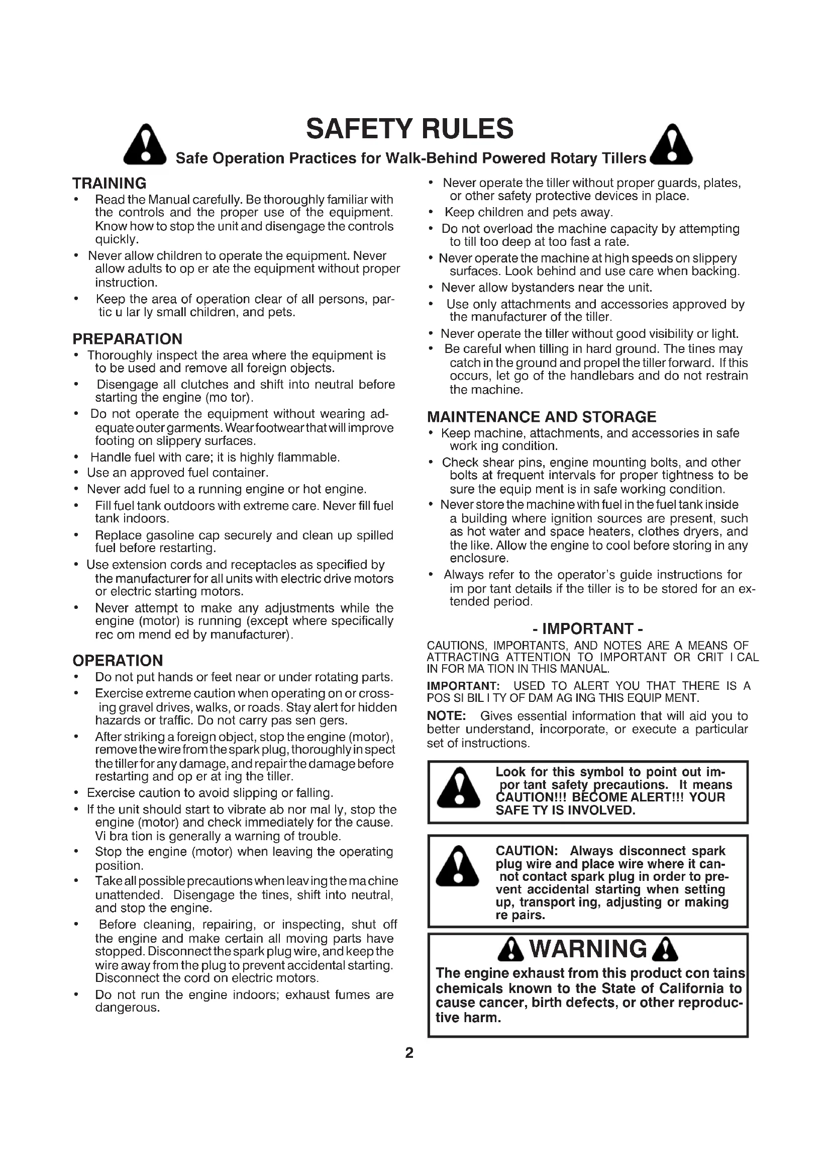
OPERATOR'S POSITION (See Fig. 1)
When right or left hand is mentioned in this manual, it means when you are in the operating position (standing behind tiller handles).
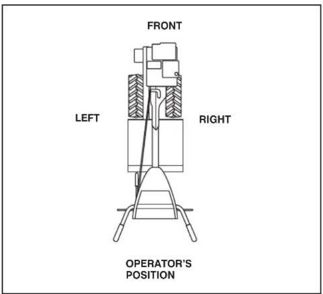
UNPACKING CARTON (See Fig. 2)

CAUTION: Be careful of exposed sta ples when handling or disposing of cartoning material.
IMPORTANT: WHEN UNPACKING AND ASSEMBLING TILLER, BE CAREFUL NOT TO STRETCH OR KINK CABLES.
- While holding handle assembly, cut cable ties securing handle assembly to top frame and depth stake. Let handle assembly rest on tiller.
- Remove top frame of carton.
- Slowly ease handle assembly up and place on top of carton.
- Cut down right hand front and right hand rear corners of carton, lay side carton wall down.
- Remove packing material from handle assembly.
text_image
HANDLE AS SEM BLY SHIFT RODFig. 2
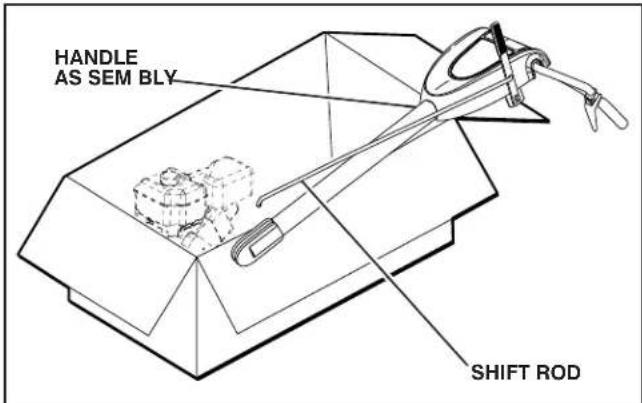
INSTALL HANDLE (See Figs. 3, 4, and 5)
- Insert one handle lock (with teeth facing outward) in gearcase notch. (Apply grease on smooth side of handle lock to aid in keeping lock in place until handle assembly is lowered into position.)
text_image
HANDLE ASSEMBLY GEARCASE NOTCH HANDLE LOCK (VIEWED FROM R.H. SIDE OF TILLER)Fig. 3
- Grasp handle assembly. Hold in "up" position. Be sure handle lock remains in gearcase notch. Slide handle assembly into position.
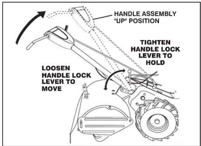
text_image
HANDLE ASSEMBLY "UP" POSITION TIGHTEN HANDLE LOCK LEVER TO HOLD LOOSEN HANDLE LOCK LEVER TO MOVEFig. 4
- Rotate handle assembly down. Insert rear carriage bolt first, with bolt head on L.H. side of tiller and loosely assemble locknut (See Fig. 5).
- Insert pivot bolt in front part of plate and tighten.
- Cut down remaining corners of carton and lay panels flat.
- Lower the handle assembly. Tighten nut on carriage bolt so handle moves with some resistance. This will allow for easier adjustment.
- Place flat washer on threaded end of handle lock lever.
- Insert handle lock lever through handle base and gearcase. Screw in handle lock lever just enough to hold lever in place.
- Insert second handle lock (with teeth in ward) in the slot of the handle base (just inside of washer).
- With handle assembly in lowest position, securely tight en handle lock lever by rotating clockwise. Leaving handle assembly in lowest position will make it easier to remove tiller from carton.
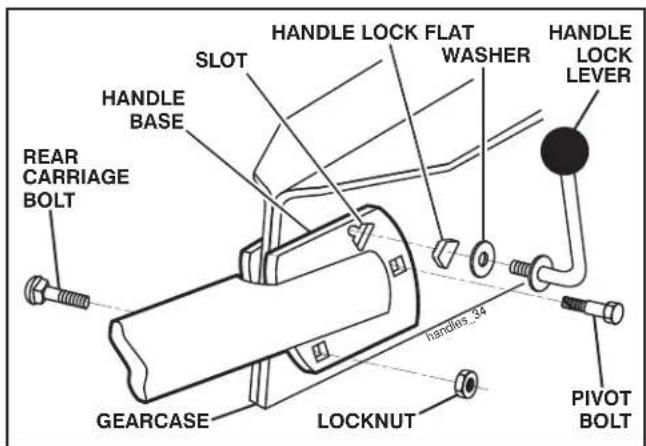
text_image
HANDLE LOCK FLAT WASHER HANDLE LOCK LEVER SLOT HANDLE BASE REAR CARRIAGE BOLT GEARCASE LOCKNUT handles 34 PIVOT BOLTFig. 5
ASSEMBLY
CONNECT SHIFT ROD (See Fig. 7)
- Insert end of shift rod into hole of shift lever indicator.
- Insert hairpin clip through hole of shift rod to secure.
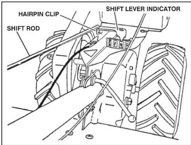
text_image
HAIRPIN CLIP SHIFT ROD SHIFT LEVER INDICATORFig. 7
REMOVE TILLER FROM CRATE
- Make sure shift lever indicator is in "N" position (See Fig. 7)
- Tilt tiller forward by lifting handle. Separate cardboard cover from leveling shield.
- Rotate tiller handle to the right and pull tiller out of carton.
CHECK TIRE PRESSURE
The tires on your unit were overinflated at the factory for shipping purposes. Correct and equal tire pressure is important for best tilling performance.
- Reduce tire pressure to 20 PSI (1.4 kg/cm ^2 ).
HANDLE HEIGHT
- Handle height may be adjusted to better suit operator. (See "TO ADJUST HANDLE HEIGHT" in the Service and Adjustments section of this manual).
OPERATION
KNOW YOUR TILLER
READ THIS OWNER'S MANUAL AND SAFETY RULES BEFORE OPERATING YOUR TILLER.
Compare the illustrations with your tiller to familiarize yourself with the location of various controls and adjustments. Save this manual for future reference.
These symbols may appear on your Tiller or in literature supplied with the product. Learn and understand their meaning.

text_image
F R N R CAUTION ENGINE STOP FAST SLOW OILFUELCHTILLING


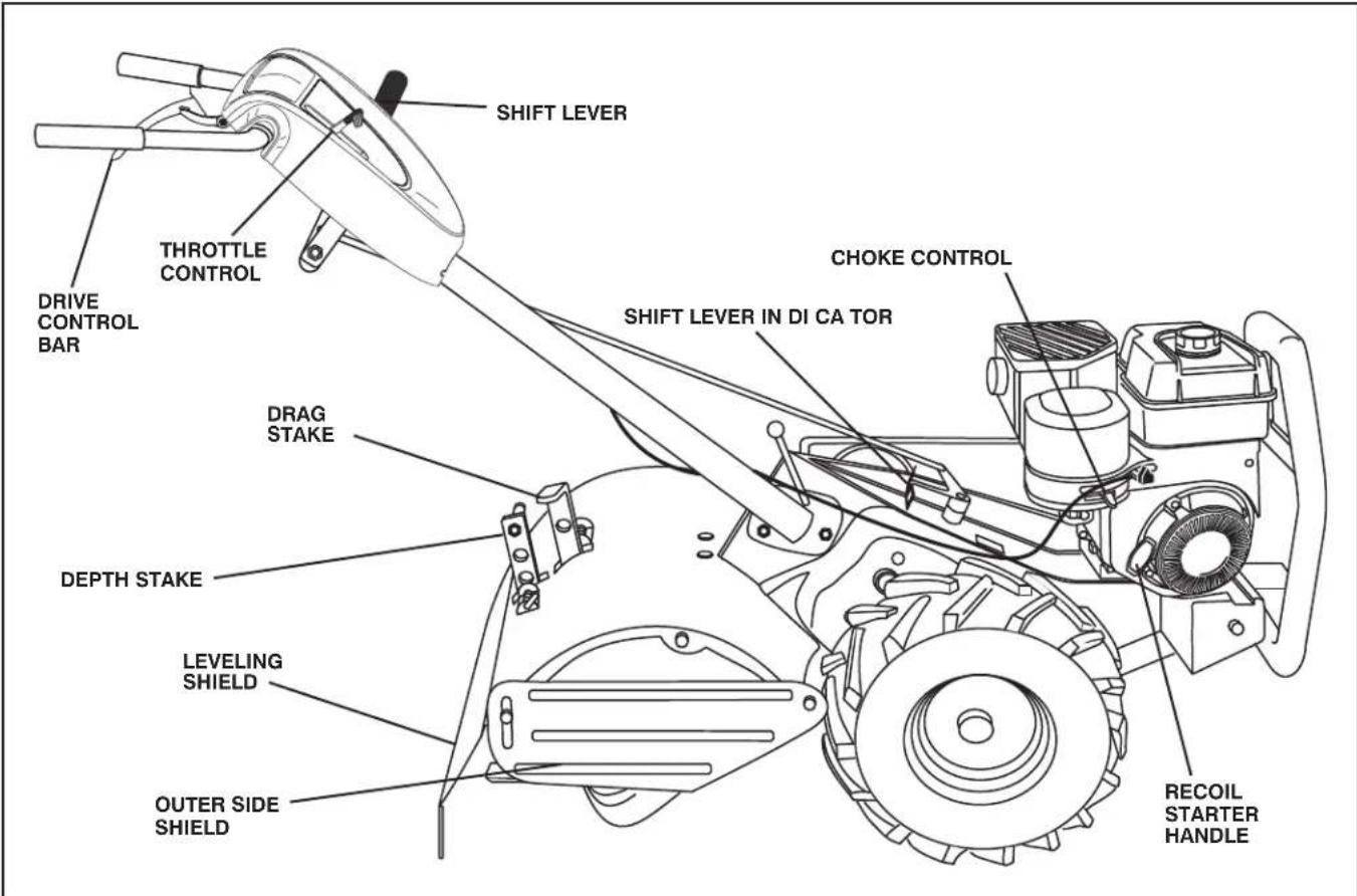
text_image
SHIFT LEVER THROTTLE CONTROL DRIVE CONTROL BAR DRAG STAKE DEPTH STAKE LEVELING SHIELD OUTER SIDE SHIELD SHIFT LEVER IN DI CA TOR CHOKE CONTROL RECOIL STARTER HANDLEFIG. 8
MEETS ANSI SAFETY REQUIREMENTS
Our tillers conform to the safety standards of the American National Standards Institute.
CHOKE CONTROL - Used when starting a cold engine.
DEPTH STAKE - Controls depth at which tiller will dig.
DRAG STAKE - Controls forward speed in forward rotating till position.
DRIVE CONTROL BAR - Used to engage tines.
LEVELING SHIELD - Levels tilled soil.
OUTER SIDE SHIELD - Adjustable to protect small plants from being buried.
RECOIL STARTER HANDLE - Used to start the engine.
SHIFT LEVER - Used to shift transmission gears.
SHIFT LEVER INDICATOR - Shows which gear the transmis sion is in.
THROTTLE CONTROL - Controls engine speed.
OPERATION

The operation of any tiller can result in foreign objects thrown into the eyes, which can result in severe eye damage. Always wear safety glasses or eye shields before starting your tiller and while tilling. We recommend a wide vision safety mask over spectacles or standard safety glasses.

Use ear protectors to avoid damage to hearing.
HOW TO USE YOUR TILLER
Know how to operate all controls before adding fuel and oil or attempting to start engine.
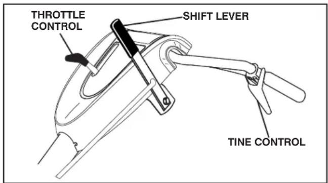
STOPPING (See Fig. 9)
TINES AND DRIVE
- Release drive control bar to stop movement.
- Move shift lever to "N" (neutral) position.
ENGINE
- Move throttle control to "STOP" position.
- Never use choke to stop engine.
text_image
THROTTLE CONTROL SHIFT LEVER TINE CONTROLFig. 8
- Always release drive control bar before moving shift lever into another position.
- Tine movement is achieved by moving shift lever to either the counter rotating (2) till position or the forward rotating (2) till position and engaging drive control bar.
FORWARD - WHEELS ONLY/TINES STOPPED
- Release drive control bar and move shift lever in di ca- tor to "F" (forward) position. Engage drive control bar and tiller will move forward.
REVERSE - WHEELS ONLY/TINES STOPPED
• DO NOT STAND DIRECTLY BEHIND TILLER.
- Release the drive control bar.
- Move throttle control to "SLOW" position.
- Move shift lever indicator to "R" (reverse) position.
- Hold drive control bar against the handle to start tiller movement.
HARD TO SHIFT GEARS
- Briefly engage drive control bar and release or rock tiller forward and backward until are able to shift gears.
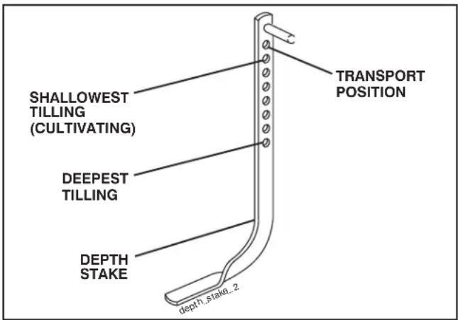
DEPTH STAKE (See Fig. 10)
The depth stake can be raised or lowered to allow you more versatile tilling and cul ti vat ing, or to more easily transport your tiller.
text_image
SHALLOWEST TILLING (CULTIVATING) DEEPEST TILLING DEPTH STAKE dept1_stake_2 TRANSPORT POSITIONFIG. 10
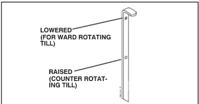
DRAG STAKE (See Fig. 11)
The drag stake should be raised when tilling in the counter rotating (2) till position. The drag stake should be lowered when tilling in the forward rotating (2) till position.
text_image
LOWERED (FOR WARD ROTATING TILL) RAISED (COUNTER ROTAT- ING TILL)FIG. 11
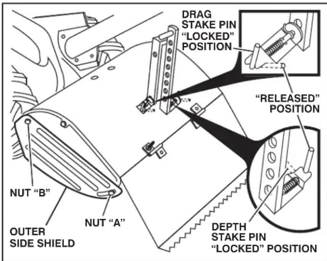
TILLING (See Fig. 12)
- Release depth stake pin. Pull the depth stake up for increased tilling depth. Place depth stake pin in hole of depth stake to lock in position.
- Place shift lever indicator in counter rotating ( till position.
- Hold the drive control bar against the handle to start tilling movement. Tines and wheels will both turn.
- Move throttle control to "FAST" position for deep tilling. To cultivate, throttle control can be set at any desired speed, depending on how fast or slow you wish to cultivate.
IMPORTANT: ALWAYS RELEASE DRIVE CONTROL BAR BEFORE MOVING SHIFT LEVER INTO ANOTHER POSITION.
OPERATION
text_image
NUT "B" OUTER SIDE SHIELD NUT "A" DRAG STAKE PIN "LOCKED" POSITION "RELEASED" POSITION DEPTH STAKE PIN "LOCKED" POSITIONFig. 12
TURNING
- Release the drive control bar.
- Move throttle control to "SLOW" position.
- Place shift lever indicator in "F" (forward) position. Tines will not turn.
- Lift handle to raise tines out of ground.
- Swing the handle in the opposite direction you wish to turn, being careful to keep feet and legs away from tines.
- When you have completed your turn-around, release the drive control bar and lower handle. Place shift lever in (till) position and move throttle control to de sired speed. To begin tilling, hold drive control bar against the handle.
CULTIVATING
- Use the forward rotating tine drive when cultivating, tilling soft ground or tilling pre-tilled soil.
- Release depth and drag stake pins. Lower drag stake. Pull the depth stake up for increased tilling depth. Place proper pin in hole of depth stake or drag stake to lock in position.
- Place shift lever indicator in forward rotating ( ) till position.
- Hold the drive control bar against the handle to start tilling movement. Tines and wheels will both turn.
- Move throttle control "FAST" position for deep tilling. To cultivate, throttle control can be set at any desired speed, depending on how fast or slow you wish to cultivate.
- Always lower the drag stake when using the forward rotating tine drive.
OUTER SIDE SHIELDS (See Fig. 12)
The back edges of the outer side shields are slotted so that the shields can be raised for deep tilling and low ered for shall low tilling to protect small plants from being buried. Loosen nut "A" in slot and nut "B". Move shield to desired position (both sides). Retighten nuts.
TO TRANSPORT

CAUTION: Before lifting or trans porting, allow tiller engine and muffler to cool. Disconnect spark plug wire. Drain gasoline from fuel tank.
AROUND THE YARD
- Release the depth stake pin. Move the depth stake down to the top hole for transporting the tiller. Place depth stake pin in hole of depth stake to lock in position. This prevents tines from scuffing the ground.
- Place shift lever indicator in "F" (forward) position for transporting.
- Hold the drive control bar against the handle to start tiller movement. Tines will not turn.
- Move throttle control to desired speed.
AROUND TOWN
- Disconnect spark plug wire.
- Drain fuel tank.
- Transport in upright position to prevent oil leakage.
BEFORE START ING ENGINE
IMPORTANT: BE VERY CAREFUL NOT TO ALLOW DIRT TO ENTER THE ENGINE WHEN CHECKING OR ADDING OIL OR FUEL. USE CLEAN OIL AND FUEL AND STORE IN APPROVED, CLEAN, COVERED CONTAINERS. USE CLEAN FILL FUNNELS.
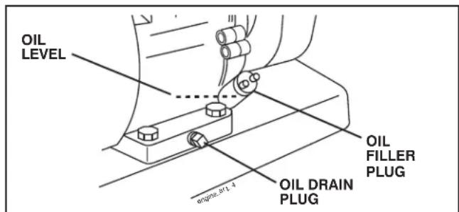
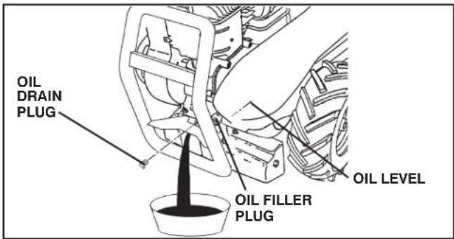
CHECK ENGINE OIL LEVEL (See Fig. 13)
- The engine in your unit has been shipped, from the factory, already filled with SAE 30 summer weight oil.
- With engine level, clean area around oil filler plug and remove plug.
- Engine oil should be to point of overflowing when engine is level. For approximate capacity see "PRODUCT SPEC I FI CATIONS" on page 3 of this manual. All oil must meet A.P.I. Service Classification SG-SL.
- Reinstall engine oil cap and tighten.
- For cold weather operation you should change oil for easier starting (See oil viscosity chart in the Maintenance section of this manual).
- To change engine oil, see the Maintenance section in this manual.
text_image
OIL LEVEL OIL FILLER PLUG OIL DRAIN PLUG 0.1 ± 4Fig. 13
OPERATION
ADD GASOLINE
- Fill fuel tank to bottom of filler neck. Do not overfill. Use fresh, clean, regular un lead ed gasoline with a minimum of 87 octane. Do not mix oil with gasoline. Purchase fuel in quan ti ties that can be used within 30 days to assure fuel freshness.

CAUTION: Fill to within 1/2 inch of top of fuel tank to prevent spills and to allow for fuel expansion. If gasoline is ac ci den tal ly spilled, move machine away from area of spill. Avoid creating any source of ignition until gasoline vapors have disappeared.
Wipe off any spilled oil or fuel. Do not store, spill or use gasoline near an open flame.
IMPORTANT: WHEN OPERATING IN TEMPERATURES BELOW 32°F(0°C), USE FRESH, CLEAN WINTER GRADE GAS O LINE TO HELP INSURE GOOD COLD WEATHER START ING.
CAUTION: Alcohol blended fuels (called gas o-hol or using ethanol or methanol) can attract moisture which leads to separation and formation of acids during storage. Acidic gas can damage the fuel system of an engine while in storage. To avoid engine problems, the fuel system should be emptied before storage of 30 days or longer. Drain the gas tank, start the engine and let it run until the fuel lines and carburetor are empty. Use fresh fuel next season. See Storage Instructions for additional information. Never use engine or carburetor cleaner products in the fuel tank or permanent damage may occur.
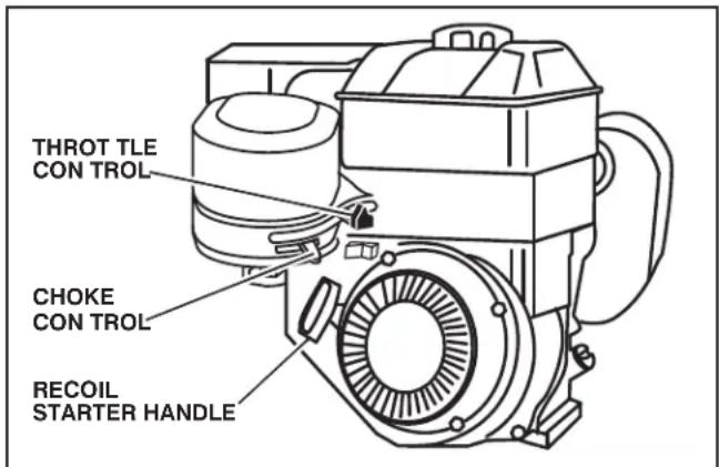
TO START ENGINE (See Fig. 14)

CAUTION: Keep drive control bar in "DISENGAGED" position when starting en gine.
When starting engine for the first time or if engine has run out of fuel, it will take extra pulls of the recoil starter to move fuel from the tank to the engine.
- Make sure spark plug wire is proper ly connected.
- Move shift lever indicator to "N" (neutral) position.
- Place throttle control in "FAST" position.
- Move choke control to full "CHOKE" position. Grasp recoil starter handle with one hand and grasp tiller handle with other hand. Pull rope out slowly until engine reaches start of com pres sion cycle (rope will pull slightly harder at this point).
- Pull recoil starter handle quickly. Do not let starter handle snap back against starter. Repeat if necessary.
- If engine fires but does not start, move choke control to half choke position. Pull recoil starter handle until engine starts.
- When engine starts, slowly move choke control to "RUN" position as engine warms up.
NOTE: A warm engine requires less choking to start.
- Move throttle control to desired running position.
- Allow engine to warm up for a few minutes before engaging tines.
NOTE: If at a high altitude (3000 feet) or in cold temperatures (below 32^ F), the carburetor fuel mixture may need to be adjusted for best engine performance. If you think the fuel mixture needs adjusting, contact your nearest authorized service center/department, which has the proper equipment and experience to make any necessary adjustments.
NOTE: If engine does not start, see troubleshooting points.
text_image
THROT TLE CON TROL CHOKE CON TROL RECOIL STARTER HANDLEFig. 14
TILLING HINTS (See Fig. 15)

CAUTION: Until you are accustomed to handling your tiller, start actual field use with throttle in slow position (mid-way between "FAST" and "IDLE").
- Tilling is digging into, turning over, and breaking up packed soil before planting. Loose, unpacked soil helps root growth. Best tilling depth is 4" to 6" (10-15 cm). A tiller will also clear the soil of unwanted vegetation. The decomposition of this vegetable matter enriches the soil. Depending on the climate (rain fall and wind), it may be advisable to till the soil at the end of the growing season to further condition the soil.
- You will find tilling much easier if you leave a row un-tilled between passes. Then go back between tilled rows. (See Fig. 14) There are two reasons for doing this. First, wide turns are much easier to negotiate than about-faces. Second, the tiller won't be pulling itself, and you, toward the row next to it.
- Soil conditions are important for proper tilling. Tines will not readily penetrate dry, hard soil which may contribute to excessive bounce and difficult handling of your tiller. Hard soil should be moistened before tilling; however, extremely wet soil will "ball-up" or clump during tilling. Wait until the soil is less wet in order to achieve the best results. When tilling in the fall, re move vines and long grass to prevent them from wrapping around the tine shaft and slowing your tilling operation.
OPERATION
- Do not lean on handle. This takes weight off the wheels and reduces traction. To get through a really tough section of sod or hard ground, apply upward pressure on handle or lower the depth stake.
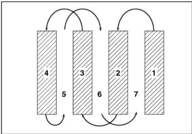
flowchart
graph TD
    A["4"] -->|5| B["3"]
    B -->|6| C["2"]
    C -->|7| D["1"]
    D -->|7| A
    A -->|7| B
    B -->|7| C
    C -->|7| D
FIG. 15
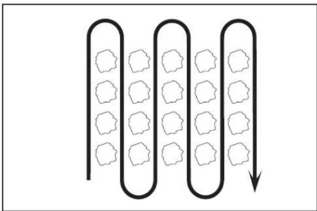
CULTIVATING
Cultivating is destroying the weeds between rows to prevent them from robbing nourishment and moisture from the plants. At the same time, breaking up the upper layer of soil crust will help retain moisture in the soil. Best digging depth is 1" to 3" (2.5-7.5 cm). Lower the outer side shields to protect small plants from being buried.
- Cultivate up and down the rows at a speed which will allow tines to uproot weeds and leave the ground in rough condition, promoting no further growth of weeds and grass (See Fig. 16).
- Do not lean on handle, this takes weight off the wheels, reduces traction, and may cause the tiller to skip over the ground.
• Always lower the drag stake when using the forward rotating tine drive.
natural_image
Diagram of a coiled tube with hexagonal patterns inside, connected by a downward arrow (no text or symbols)FIG. 16
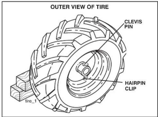
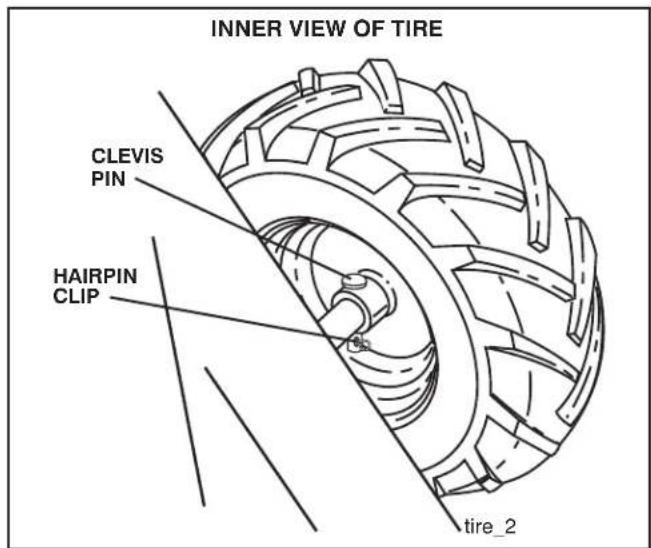
ADJUST WHEELS FOR CULTIVATING (See Figs. 17 and 18)
- Place blocks under right hand side of tiller and remove hairpin clip and clevis pin from right hand wheel.
- Move wheel outward approximately 1 inch until hole in inner wheel hub lines up with inner hole in axle.
- Replace clevis pin and hairpin clip on inside of wheel and remove blocks.
- Repeat preceding steps on left hand side.
NOTE: In extremely rough conditions and while cultivating, the wheels should be moved outward on the axle for increased stability.
text_image
OUTER VIEW OF TIRE CLEVIS PIN HAIRPIN CLIP tire_1FIG. 17
text_image
INNER VIEW OF TIRE CLEVIS PIN HAIRPIN CLIP tire_2FIG. 18
MAINTENANCE
| MAINTENANCE SCHEDULEFILL IN DATESAS YOU COMPLETEREGULAR SERVICE | BEFORE EACH USEEVERY 5 HOURSEVERY 25 HOURSEVERY 50 HOURSEVERY SEASON | ||||||||||||
| Check Engine Oil Level | √ | √ | |||||||||||
| Change Engine Oil | 1,2 | ||||||||||||
| Oil Pivot Points | √ | ||||||||||||
| Inspect Spark Arrester / Muffler | √ | ||||||||||||
| Inspect Air Screen | √ | ||||||||||||
| Clean or Replace Air Cleaner Cartridge | √2 | ||||||||||||
| Clean Engine Cylinder Fins | √ | ||||||||||||
| Replace Spark Plug | √ | ||||||||||||
| RH Gear Case Grease Fitting (1oz.) | √ | ||||||||||||
1 - Change more often when operating under a heavy load or in high ambient temperatures.
2 - Service more often when operating in dirty or dusty conditions.
GENERAL RECOMMENDATIONS
The warranty on this tiller does not cover items that have been subjected to operator abuse or negligence. To receive full value from the warranty, the operator must main tain tiller as instructed in this manual.
Some adjustments will need to be made periodically to properly maintain your tiller.
All adjustments in the Service and Adjustments section of this manual should be checked at least once each season.
- Once a year you should replace the spark plug, clean or replace air filter, and check tines and belts for wear. A new spark plug and clean air filter assure proper air-fuel mixture and help your engine run better and last longer.
BEFORE EACH USE
- Check engine oil level.
- Check tine operation.
- Check for loose fasteners.
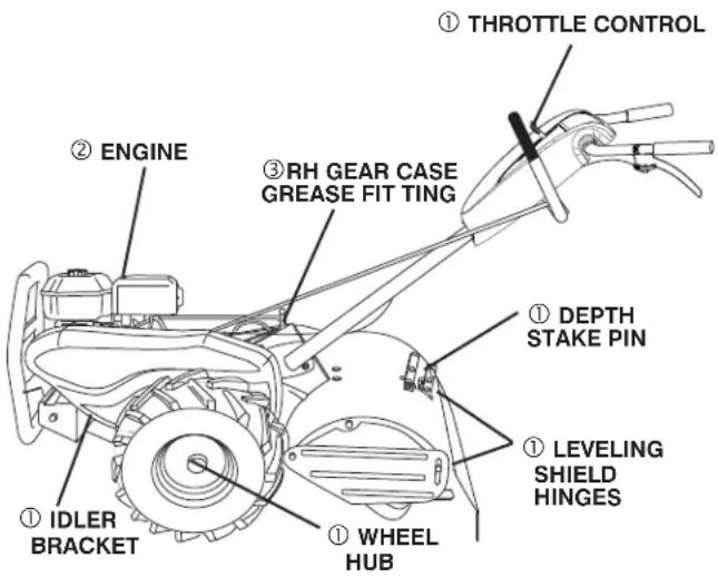
LUBRICATION
Keep unit well lubricated (See "LUBRICATION CHART").
LUBRICATION CHART
text_image
① THROTTLE CONTROL ② ENGINE ③ RH GEAR CASE GREASE FIT TING ① DEPTH STAKE PIN ① LEVELING SHIELD HINGES ① IDLER BRACKET ① WHEEL HUB①SAE 30 OR 10W-30 MOTOR OIL
②REFER TO MAINTENANCE "ENGINE" SECTION
③EP #1 GREASE
MAINTENANCE

Disconnect the spark plug wire before performing any maintenance to prevent accidental starting of the engine.
Prevent fires! Keep the engine free of grass, leaves, spilled oil, or fuel. Re move fuel from tank before tipping unit for maintenance. Clean muffler area of all grass, dirt, and debris.
Do not touch hot muffler or cylinder fins as contact may cause burns.
ENGINE
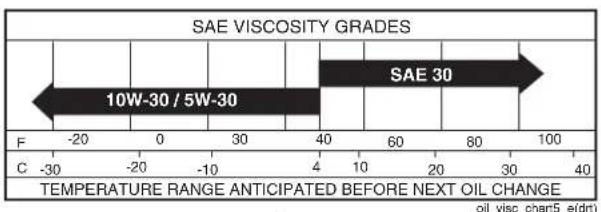
LUBRICATION
Use only high quality detergent oil rated with API service classification SG-SL. Select the oil's SAE vis cos i ty grade according to your expected temperature.
text_image
SAE VISCOSITY GRADES 10W-30 / 5W-30 SAE 30 F -20 0 30 40 60 80 100 C -30 -20 -10 4 10 20 30 40 TEMPERATURE RANGE ANTICIPATED BEFORE NEXT OIL CHANGE oil_visc_chart5_e(dtt)FIG. 19
NOTE: Although multi-viscosity oils (5W-30, 10W-30, etc.) improve starting in cold weather, these multi-viscosity oils will result in increased oil consumption when used above 40°F (4°C). Check your engine oil level more frequently to avoid possible engine damage from running low on oil.
Change the oil after every 25 hours of operation or at least once a year if the tiller is not used for 25 hours in one year.
Check the crankcase oil level before starting the engine and after each five (5) hours of continuous use. Add SAE 30 motor oil or equivalent. Tighten oil filler plug securely each time you check the oil level.
TO CHANGE ENGINE OIL (See Figs. 19 and 20)
- Be sure tiller is on level surface.
• Oil will drain more freely when warm. - Use a funnel to prevent oil spill on tiller, and catch oil in a suitable container.
- Remove drain plug.
- For easier removal of plug use 7/16 12 Pt. socket with extension.
• Tip tiller forward to drain oil.
• After oil has drained completely, replace oil drain plug and tighten securely. - Remove oil filler plug. Be careful not to allow dirt to enter the engine.
- Refill engine with oil. See "CHECK ENGINE OIL LEVEL" in the Operation section of this manual.
text_image
OIL DRAIN PLUG OIL FILLER PLUG OIL LEVELFIG. 20
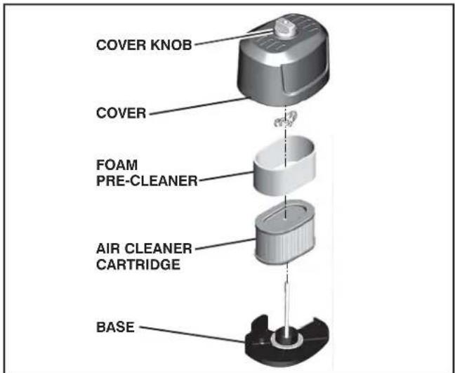
AIR FILTER (See Fig. 21)
Your engine will not run properly using a dirty air filter. Clean the foam pre-cleaner after every 25 hours of operation or every season. Service paper cartridge every 100 hours of operation or every season, which ever occurs first. Service air cleaner more often under dusty conditions.
- Remove cover knob and cover.
TO SERVICE PRE-CLEANER
- Remove foam pre-cleaner from air cleaner cover.
- Wash it in liquid detergent and water.
- Squeeze it dry in a clean cloth.
- If very dirty or damaged, replace pre-cleaner.
- Reinstall pre-cleaner into air cleaner cover.
- Reinstall cover and secure screw.
TO SERVICE CARTRIDGE
- Carefully remove cartridge to prevent debris from enter ing carburetor. Clean base carefully to pre vent debris from entering carburetor.
- Clean cartridge by tap ping gently on flat surface. If very dirty or damaged, replace cartridge.
- Reinstall cartridge, cover with pre-cleaner and secure with screw.
IMPORTANT: PETROLEUM SOLVENTS, SUCH AS KERO SENE, ARE NOT TO BE USED TO CLEAN THE CAR TRIDGE. THEY MAY CAUSE DETERIORATION OF THE CARTRIDGE. DO NOT OIL CARTRIDGE. DO NOT USE PRESSURIZED AIR TO CLEAN OR DRY CARTRIDGE.
text_image
COVER KNOB COVER FOAM PRE-CLEANER AIR CLEANER CARTRIDGE BASEFig. 21
MAINTENANCE
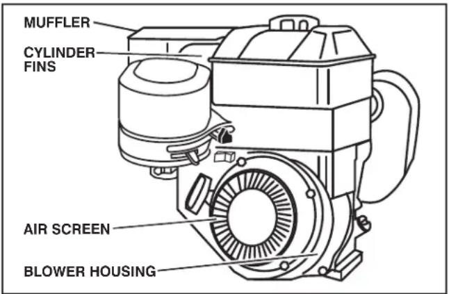
COOLING SYSTEM (See Fig. 22)
Your engine is air cooled. For proper engine performance and long life keep your engine clean.
- Clean air screen frequently using a stiff-bristledbrush.
- Remove blower housing and clean as nec es sary.
- Keep cylinder fins free of dirt and chaff.
text_image
MUFFLER CYLINDER FINS AIR SCREEN BLOWER HOUSINGFig. 22
MUFFLER
Do not operate tiller without muffler. Do not tamper with exhaust system. Damaged mufflers or spark arresters could create a fire hazard. Inspect pe ri odi cally and re place if nec es sary. If your engine is equipped with a spark arrester screen assembly, re move every 50 hours for cleaning and inspection. Re place if dam aged.
SPARK PLUG
Replace spark plugs at the beginning of each tilling season or after every 50 hours of use, whichever comes first. Spark plug type and gap setting is shown in "PRODUCT SPEC I FI CA TIONS" on page 3 of this manual.
TRANSMISSION
Once a season, lubricate the right hand side gear case grease fitting with 1 oz. of EP #1 Grease.
CLEANING
Do not clean your tiller when the engine and transmission are hot. We do not rec om mend using pressurized water (gar den hose, etc.) to clean your unit un less the gasket area around the trans mis sion and the engine muf fler, air filter and carburetor are covered to keep water out. Water in en gine will short en the useful life of your tiller.
- Clean engine, wheels, finish, etc. of all foreign matter.
- Keep finished surfaces and wheels free of all gas o line, oil, etc.
- Protect painted surfaces with au to mo tive type wax.
SERVICE AND ADJUSTMENTS

CAUTION: Disconnect spark plug wire from spark plug and place wire where it cannot come into contact with plug.
TILLER
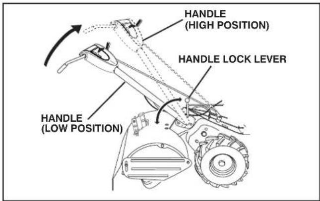
TO ADJUST HANDLE HEIGHT (See Fig. 23)
Select handle height best suited for your tilling conditions. Handle height will be different when tiller digs into soil.
- First loosen handle lock lever.
- Handle can be positioned at different settings between "HIGH" and "LOW" positions.
- Retighten handle lock lever securely after adjusting.
text_image
HANDLE (HIGH POSITION) HANDLE LOCK LEVER HANDLE (LOW POSITION)Fig. 22
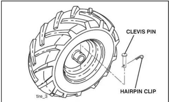
text_image
CLEVIS PIN HAIRPIN CLIP tire_3FIG. 24
TO REMOVE BELT GUARD (See Fig. 25)
NOTE: For ease of removal, remove hairpin clip and clevis pin from left wheel. Pull wheel out from tiller about 1 inch.
- Remove two (2) screws from side of belt guard.
- Remove hex nut and washer from bottom of belt guard (located behind wheel).
• Pull belt guard out and away from unit. - Replace belt guard by reversing above procedure.
TIRE CARE

CAUTION: When mounting tires, unless beads are seated, over in flation can cause an explosion.
- Maintain 20 pounds of tire pressure. If tire pressures are not equal, tiller will pull to one side.
- Keep tires free of gasoline or oil which can damage rubber.
TO REMOVE WHEEL (See Fig. 24)
- Place blocks under trans mis sion to keep tiller from tipping.
- Remove hairpin clip and clevis pin from wheel.
- Remove wheel and tire.
• Repair tire and reassemble.
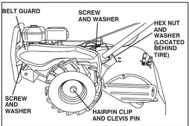
text_image
BELT GUARD SCREW AND WASHER HEX NUT AND WASHER (LOCATED BEHIND TIRE) SCREW AND WASHER HAIRPIN CLIP AND CLEVIS PINFIG. 25
SERVICE AND ADJUSTMENTS
TO REPLACE GROUND DRIVE BELT (See Figs. 25 and 26)
- Remove belt guard as described in "TO REMOVE BELT GUARD".
- Remove old belt by slipping off engine pulley first then remove from transmission pulley.
- Place new belt in groove of transmission pulley and into engine pulley. BELT MUST BE IN GROOVE ON TOP OF IDLER PULLEY. NOTE POSITION OF BELT TO GUIDES.
- Check belt adjustment as described below.
- Replace belt guard.
- Reposition wheel and replace clevis pin and hairpin clip.
GROUND DRIVE BELT ADJUSTMENT (See Fig. 26)
For proper belt tension, the extension spring should have about 5/8 inch (16 mm) stretch when drive control bar is in "EN GAGED" position. This tension can be attained as follows:
- Loosen cable clip screw securing the drive control cable.
- Slide cable forward for less tension and rearward for more tension until about 5/8 inch (16 mm) stretch is obtained while the drive control bar is engaged.
- Tighten cable clip screw securely.
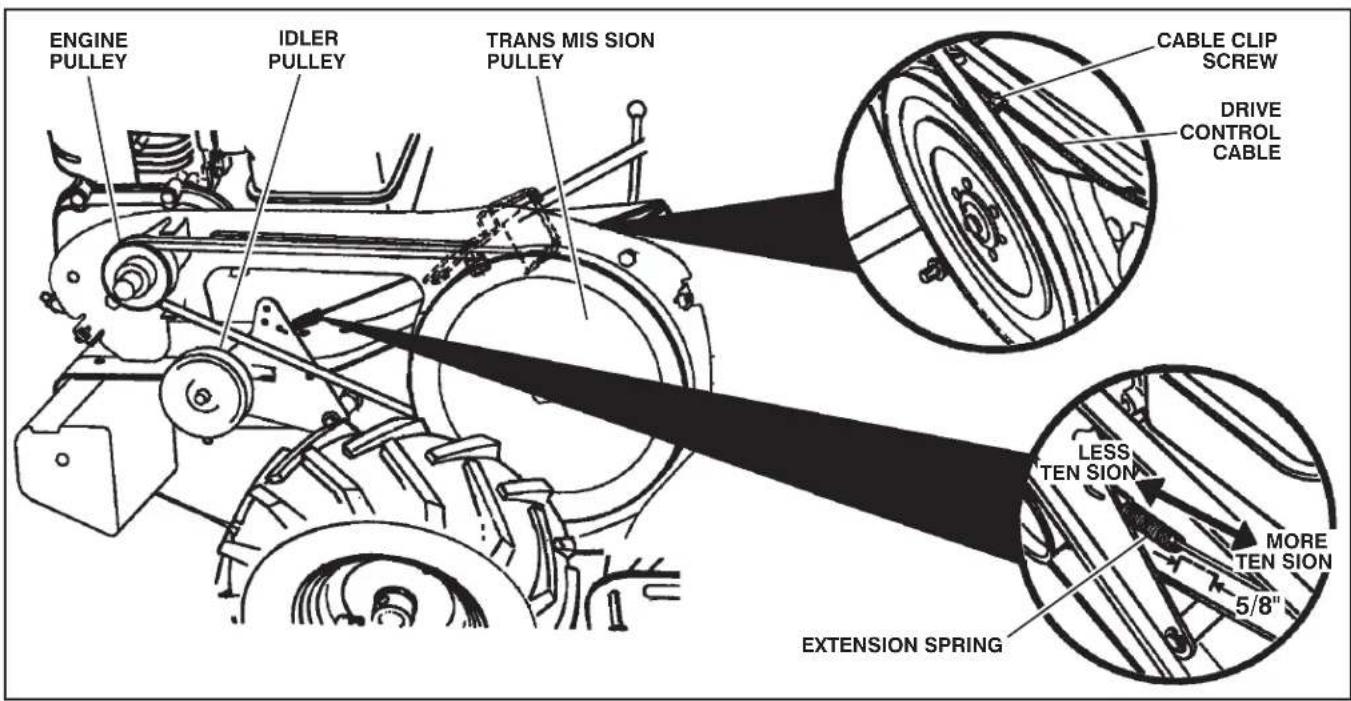
text_image
ENGINE PULLEY IDLER PULLEY TRANS MIS SION PULLEY CABLE CLIP SCREW DRIVE CONTROL CABLE LESS TEN SION MORE TEN SION 5/8" EXTENSION SPRINGFig. 26
SERVICE AND ADJUSTMENTS
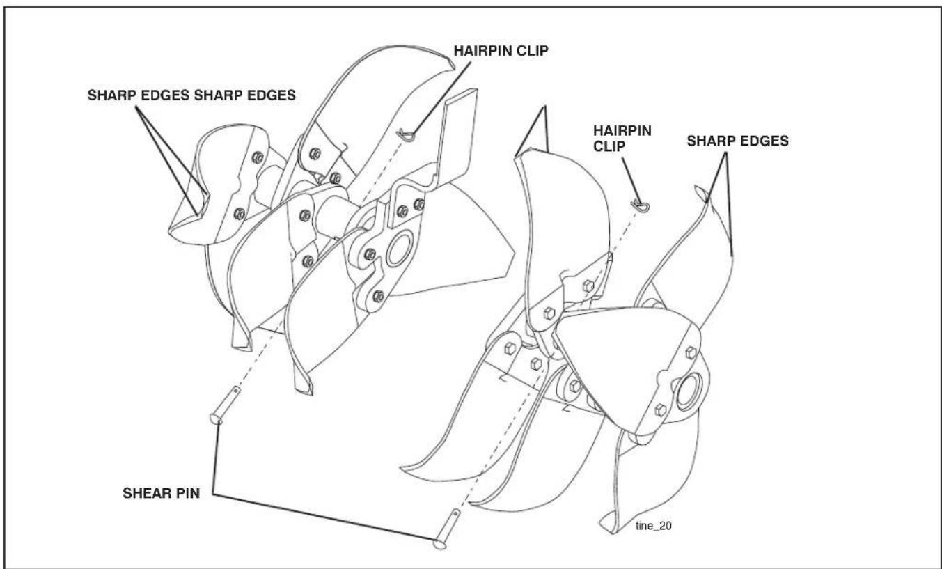
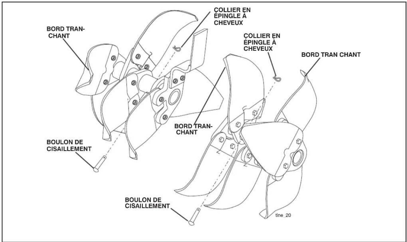
TINE REPLACEMENT (See Figs. 27, 28 and 29)

CAUTION: Tines are sharp. Wear gloves or other protection when handling tines.
A badly worn tine causes your tiller to work harder and dig more shallow. Most important, worn tines cannot chop and shred organic matter as effectively nor bury it as deeply as good tines. A tine this worn needs to be replaced.
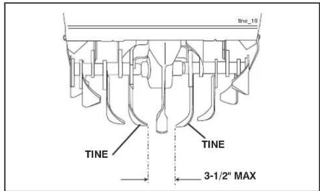
- To maintain the superb tilling performance of this machine the tines should be checked for sharpness, wear, and bending, particularly the tines which are next to the transmission. If the gap between the tines ex ceeds 3-1/2" they should be replaced or straightened as necessary.
- For tines that are slightly worn, the bolt ed tine and hub assemblies can be switched between sides to continue till ing in the same tilling mode if tilling in a different mode is desired then the bolt ed tine and hub assemblies should be switched back to their original side so that the tine edge with the least wear will be used.
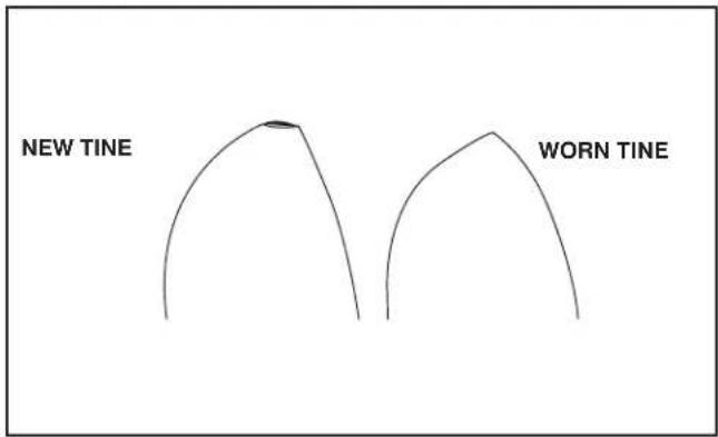
text_image
NEW TINE WORN TINEFIG. 27
text_image
line_19 TINE TINE 3-1/2" MAXFIG. 28
text_image
SHARP EDGES SHARP EDGES HAIRPIN CLIP HAIRPIN CLIP SHARP EDGES SHEAR PIN tine_20FIG. 29
SERVICE AND ADJUSTMENTS
ENGINE
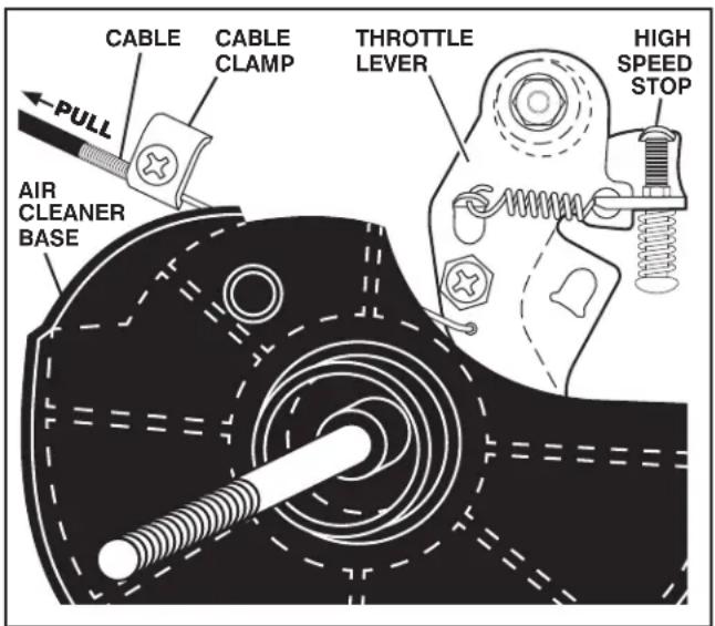
TO ADJUST THROTTLE CONTROL CABLE (See Fig. 30)
The throttle control has been preset at the factory and ad just ment should not be necessary. If adjustment is necessary, proceed as follows:
- With engine not running, remove air cleaner cover and cartridge (See “AIR CLEANER” in the Maintenance section of this manual).
- Move remote throttle control to "FAST" position.
- If throttle lever on engine touches high speed stop, no further adjustment is necessary. If throttle lever does not touch high speed stop, continue with adjustment procedure.
- Loosen cable clamp screw.
- Pull cable backward until throttle lever contacts the high speed stop, and hold in this position.
- Tighten cable clamp screw securely.
- Reinstall air cleaner cover and cartridge.
text_image
CABLE CABLE CLAMP THROTTLE LEVER HIGH SPEED STOP AIR CLEANER BASE PULLFig. 30
TO AD JUST CARBURETOR
The carburetor has been preset at the factory and is not adjustable.
IMPORTANT: NEVER TAMPER WITH THE ENGINE GOVERNOR, WHICH IS FACTORY SET FOR PROPER ENGINE SPEED. OVERSPEED ING THE ENGINE ABOVE THE FACTORY HIGH SPEED SETTING CAN BE DANGEROUS. IF YOU THINK THE ENGINE-GOVERNED HIGH SPEED NEEDS ADJUSTING, CONTACT YOUR NEAREST AUTHORIZED SERVICE CENTER/DEPARTMENT, WHICH HAS THE PROPER EQUIP MENT AND EXPERIENCE TO MAKE ANY NEC ES SARY ADJUSTMENTS.
STORAGE
Immediately prepare your tiller for storage at the end of the season or if the unit will not be used for 30 days or more.

CAUTION: Never store the tiller with gasoline in the tank inside a build ing where fumes may reach an open flame or spark. Allow the engine to cool before storing in any enclosure.
TILLER
- Clean entire tiller (See "CLEANING" in the Maintenance section of this manual).
- Inspect and replace belts, if nec es sary (See belt replacement instructions in the Service and Adjustments section of this manual).
- Lubricate as shown in the Maintenance section of this manual.
- Be sure that all nuts, bolts and screws are securely fastened. Inspect moving parts for damage, break age and wear. Replace if necessary.
- Touch up all rusted or chipped paint surfaces; sand lightly before painting.
ENGINE
FUEL SYSTEM
IMPORTANT: IT IS IMPORTANT TO PREVENT GUM DEPOSITS FROM FORMING IN ESSENTIAL FUEL SYSTEM PARTS SUCH AS THE CARBURETOR, FUEL FILTER, FUEL HOSE, OR TANK DURING STORAGE. ALSO, EXPERIENCE INDICATES THAT ALCOHOL BLENDED FUELS (CALLED GASOHOL OR USING ETHANOL OR METHANOL) CAN ATTRACT MOISTURE WHICH LEADS TO SEPARATION AND FORMATION OF ACIDS DURING STORAGE. ACIDIC GAS CAN DAMAGE THE FUEL SYSTEM OF AN ENGINE WHILE IN STORAGE.
- Empty the fuel tank by starting the engine and let it run until the fuel lines and carburetor are empty.
- Never use engine or carburetor cleaner products in the fuel tank or permanent.
- Use fresh fuel next season.
NOTE: Fuel stabilizer is an acceptable alternative in minimizing the formation of fuel gum deposits during storage. Add stabilizer to gasoline in fuel tank or storage container. Always follow the mix ratio found on stabilizer container. Run engine at least 10 minutes after adding stabilizer to allow the stabilizer to reach the carburetor. Do not empty the gas tank and carburetor if using fuel stabilizer.
ENGINE OIL
Drain oil (with engine warm) and replace with clean oil. (See "ENGINE" in the Maintenance section of this manual).
CYLINDER(S)
- Remove spark plug.
- Pour 1 ounce (29 ml) of oil through spark plug hole into cylinder.
- Pull starter handle slowly several times to distribute oil.
- Replace with new spark plug.
OTHER
- Do not store gasoline from one season to another.
- Replace your gasoline can if your can starts to rust. Rust and/or dirt in your gasoline will cause problems.
- If possible, store your unit indoors and cover it to give protection from dust and dirt.
- Cover your unit with a suitable pro tec tive cover that does not retain moisture. Do not use plastic. Plastic cannot breathe which allows con den sa tion to form and will cause your unit to rust.
IMPORTANT: NEVER COVER TILLER WHILE ENGINE AND EXHAUST AREAS ARE STILL WARM.
TROUBLESHOOTING POINTS
| PROBLEM | CAUSE | CORRECTION |
| Will not start1. Out of fuel. 1. Fill fuel tank.2. Engine not “CHOKED” properly. 2. See “TO START ENGINE” in the Operation section.3. Engine flooded. 3. Wait several minutes before attempting to start.4. Dirty air cleaner. 4. Clean or replace air cleaner cartridge.5. Water in fuel. 5. Empty fuel tank and carburetor, and refill tank with6. Clogged fuel tank. 6. Remove fuel tank and clean.7. Loose spark plug wire. 7. Make sure spark plug wire is seated properly on8. Bad spark plug or improper gap. 8. Replace spark plug or adjust gap. | ||
| Hard to start2. Dirty air cleaner. 2. Clean or replace air cleaner cartridge.3. Bad spark plug or improper gap. 3. Replace spark plug or adjust gap.4. Stale or dirty fuel. 4. Empty fuel tank and refill with fresh gasoline.5. Loose spark plug wire. 5. Make sure spark plug wire is seated properly on | ||
| Loss of power2. Dirty air cleaner. 2. Clean or replace air cleaner cartridge.3. Low oil level/dirty oil. 3. Check oil level/change oil.4. Faulty spark plug. 4. Clean and regap or change spark plug.5. Oil in fuel. 5. Empty and clean fuel tank and refill, and clean6. Stale or dirty fuel. 6. Empty fuel tank and refill with fresh gasoline.7. Water in fuel. 7. Empty fuel tank and carburetor, and refill tank with8. Clogged fuel tank. 8. Remove fuel tank and clean.9. Connect and tighten spark plug wire.10. Dirty engine air screen.11. Dirty/clogged muffler.12. Poor compression.10. Clean engine air screen.11. Clean/replace muffler.12. Contact an authorized service center/department. | ||
| Engine overheats2. Dirty engine air screen. 2. Clean engine air screen.3. Dirty engine. 3. Clean cylinder fins, air screen, muffler area.4. Partially plugged muffler. | ||
| Excessive bounce/difficult handling2. Wheels & depth stake incorrectly adjusted. 2. Adjust wheels and depth stake. | ||
| Soil balls up or clumps | 1. Ground too dry and hard.2. Adjust wheels and depth stake. | 1. Wait for more favorable soil conditions. |
| Engine runs but tiller won’t move3. V-belt is off pulley(s). | 1. Tine control is not engaged.2. V-belt not correctly adjusted.3. Inspect V-belt. | 1. Engage tine control.2. Inspect/adjust V-belt. |
| Engine runs but labors when tilling | 1. Tilling too deep.2. Throttle control not properly adjusted. | 1. Set depth stake for shallower tilling.2. Check throttle control setting. |
LIMITED WARRANTY
What is covered. We warrant that this product is free from defects in material or workmanship under normal use and maintenance. Certain components, such as normal wear parts, engines, and transmissions are excluded from this warranty. We will, at our option, repair or replace any defective product or part covered by the Limited Warranty, free of charge at any authorized Servicing Dealer/Center using OEM replacement parts, subject to the limitations and exclusions described below.
Limited Warranty period. We will warrant the product to the original retail purchaser from the date of retail purchase for the applicable period of time shown on the chart below.
What is NOT covered. This Limited Warranty does not cover:
(a) Engines and transmissions, except as noted on the chart below; a separate warranty provided with your product might apply.
(b) Normal wear parts (parts and items that normally wear out with use), including without limitation spark plugs, bulbs, filters, lubricants, starter cords, belts, blades, and blade adapters are not covered, nor is damage due to normal wear, such as abrasion to mower decks, tires punctured by an external source, natural discoloration of materials, or dulling or damage to blades due to contact with abrasives, rocks, rods, or other foreign objects.
(c) Emissions control equipment and components to the extent regulated by the U.S. Environmental Protection Agency or similar government agencies. These are covered by a separate emission control warranty contained in the operator's manual.
(d) Depending on the product, there is either NO WARRANTY or a reduced warranty if the product is used for commercial, non-residential, or rental purposes and, in such circumstances, this Limited Warranty is offered instead of and replaces any warranty regime provided by law. Please refer to the chart below.
(e) Damage related to abuse, misuse, neglect, modifications, alterations, use of unauthorized attachments, improper storage, or lack of lubrication or engine failure due to the use of oils that do not meet engine manufacturer's specifications, pressure cleaning or steam cleaning the product, excessive dirt, abrasives, salt water, moisture, corrosion, rust, or varnish. Failure to perform required maintenance as described in the operator's manual will void this warranty.
(f) Damage or failures due to improper set up, pre-delivery service or repair service by anyone other than an authorized servicing dealer during the warranty period.
(g) Damage caused by use of gasoline containing more than 10% (E10) ethanol content (e.g. E15, E25, E30, E50, E85), use of ether or similar starting fluids, or stale fuel.
(h) Damage to sprayers from using caustic or flammable materials in the sprayer, or lack of or broken strainers.
Your Responsibilities. To preserve your rights under this Limited Warranty, you must exercise reasonable care and use of the product, including following the preventive maintenance, storage, and fuel and oil usages as prescribed in the operator's manual. Any adjustment (e.g. to the throttle cable or belt guides) after the first thirty days of purchase and any preventive maintenance as outlined in the operator's manual are NOT covered. In addition, you must cease using the product immediately upon any failure or damage, and take the product to an authorized servicing dealer prior to any further use.
WARRANTY EXCLUSIONS, DISCLAIMERS, AND LIMITED RIGHTS. WE WILL NOT BE LIABLE FOR ANY INCIDENTAL OR CONSEQUENTIAL DAMAGES. YOUR REMEDY IS LIMITED TO REPAIR OR REPLACEMENT OF THE PRODUCT OR PART, AT OUR DISCRETION. THERE ARE NO EXPRESS WARRANTIES OTHER THAN THOSE SET FORTH HEREIN. ANY WARRANTY IMPLIED BY STATE LAW (WHETHER OF MERCHANTABILITY OR FITNESS FOR A PARTICULAR USE OR OTHERWISE) IS HEREBY DISCLAIMED; WHERE SUCH A DISCLAIMER IS NOT PERMITTED BY LAW, THEN SUCH IMPLIED WARRANTY IS LIMITED FOR THE DURATION OF THE APPLICABLE LIMITED WARRANTY PERIOD LISTED IN THE CHART BELOW. SOME LOCALITIES, INCLUDING THE PROVINCE OF QUEBEC, DO NOT ALLOW EXCLUSIONS OF INCIDENTAL OR CONSEQUENTIAL DAMAGES OR LIMITATIONS ON HOW LONG AN IMPLIED WARRANTY LASTS, SO THE ABOVE EXCLUSIONS AND LIMITATIONS MAY NOT APPLY TO YOU. THIS LIMITED WARRANTY GIVES YOU SPECIFIC LEGAL RIGHTS, AND YOU MAY ALSO HAVE OTHER RIGHTS BASED ON YOUR LOCALITY.
How to obtain service. To obtain warranty service, you must take your product to an authorized Servicing Dealer/Center. To find your nearest authorized Servicing Dealer/Center, visit our website and use the Dealer Locator feature, or call 1-800-487-5951 (US) or 1-800-805-5523 (Canada) from 8:00 AM to 7:00 PM EST. Any costs to transport or ship the product are your responsibility. You must present proof of purchase (including date, product model and serial number) to an authorized Servicing Dealer/Center for warranty service. Proof of purchase rests solely with you. You may register your product using our online product registration site to help ensure that you are notified of important product information. However, registering your product is not a condition of warranty service.
Jonsered®
www.jonsered.com/us or www.jonsered.com/ca
2015 587 47 08-01 Rev. A 2014-09-30
| Jonsered® Warranty Chart 2015 586 47 08-01 | Consumer (personal, household use only) | Commercial (any commercial, professional, agricultural, institutional or income producing use, other than rental use) | Rental (any rental usage) | |
| HANDHELD PRODUCTS | ||||
| Chain Saws, including engines (*) | 2 Years 90 days 90 days | |||
| Forestry Clearing Saws, including engines (1) | 2 Years 2 Years 90 days | |||
| All Other Handheld Products, including engines (1) | 2 Years 90 days 90 days | |||
| Attachments (Split boom models) (1) | 2 Years 90 Days 90 days | |||
| WHEELED PRODUCTS | ||||
| Landowner Zero Turn Mowers ZXF | 3 Years 1 Year No Warranty | |||
| Residential Zero Turn Mowers ZR, ZF (2) (3) | 3 Years | No Warranty | No Warranty | |
| Lawn Tractors (2) (3) | 3 Years | No Warranty | No Warranty | |
| Frame, Chassis, Front Axle | 5 Years | No Warranty | No Warranty | |
| Walk Behind Mowers, High Wheel Trimmer | 3 Years | No Warranty | No Warranty | |
| Snow Throwers, Tillers (1) (2) (3) | 3 Years 90 days 90 days | |||
| Lead-Acid Batteries (for all wheeled products) (4) | 180 days | 180 days | 180 days | |
| Engines | ||||
| Rato, LCT, Locin | 2 years | 90 days | No Warranty | |
| All Others | See Note 2 | See Note 2 | See Note 2 | |
| Transmission / Drive Systems | ||||
| Tuff Torq, General Transmission | 2 Years | No Warranty | No Warranty | |
| Peerless | 3 Years | No Warranty | No Warranty | |
| Hydro-Gear | See note 3 See note 3 | See note 3 | ||
| All Others | See note 3 See note 3 | See note 3 | ||
| Decks | ||||
| Zero-Turn Mowers and Riding Tractors with steel reinforced stamped deck shell have the Limited Warranty | 10 Years | No Warranty | No Warranty | |
| Zero-Turn Mowers and Riding Tractors fabricated deck shell | See Note 1 | No Warranty | No Warranty | |
| PARTS AND ACCESSORIES | ||||
| Parts and Accessories (if purchased) (5) | ||||
| Collection Systems and Baggers | 1 Year | 90 days | No Warranty | |
| All other accessories (e.g., bars, chains, carrying cases, trimmer heads, trimmer guards, personnel protective equipment, etc.) | 90 days 30 days | No Warranty | ||
| Parts (e.g., belts, blades, starter covers, starter springs, etc.) | 30 days 30 days | No Warranty | ||
| Reconditioned or Refurbished Products | 30 days | No Warranty | No Warranty | |
| Sprayers | 1 Year | 1 Year | 1 Year | |
1 Ignition modules, tiller tines, fabricated decks, and trimmer shafts all have a “Limited Lifetime Warranty,” and are warranted for the life of the product or 7 (seven) years after the product’s final production run, whichever comes first. Parts and labor are included in the initial warranty period; labor is excluded after the initial warranty period expires. Pole Saws and Pole Hedge Trimmers are excluded from the “Limited Lifetime Warranty.” Deck Shell replacement will be limited to a maximum of two (2) deck shells within the Limited Lifetime Warranty.
2 Your engine is warranted separately by the engine manufacturer; please refer to the separate engine warranty provided with your product.
3 ZX Landowner - (ZT3100 transmission):
Hydro-Gear warrants transmission for one (1) year commercial warranty, parts and labor.
ZX Landowner - (ZT3100 transmission):
Hydro-Gear warrants transmission for two (2) years consumer warranty, parts and labor.
Snow Throwers and Lawn Tractors: two (2) years consumer warranty, parts and labor.
For all others, your transmission is warranted separately by the transmission manufacturer; please refer to the separate transmission warranty provided with your product.
4 Battery warranty does not include discharged or uncharged batteries.
5 Replacement parts and accessories provided under this Limited Warranty are warranted only for the BALANCE of the warranty period applicable to the part or accessory that was replaced.
Product Registration
Please register your product at www.jonsered.com.
Go to "Support" then "Product Registration"
You may call 1-800-487-5951 (US) or 1-800-805-5523 (Canada) to have your product registered.
Please have all product information ready prior to calling Consumer Support.
Thank you for choosing Jonsered.

RÈGLES DE SÉCURITÉ
natural_image
Diagram of a coiled tube with hexagonal patterns and a downward arrow, no text or symbols presentFIG. 16
bar
DEGRÉ DE VISCOSITÉ SAE | Temperature Range | Value | | :--- | :--- | | -20 to 0 | -20 to 0 | | 0 to 30 | -10 to 30 | | 30 to 40 | 0 to 32 | | 40 to 60 | 10 to 60 | | 60 to 80 | 20 to 80 | | 80 to 100 | 30 to 100 | TABLEAU DES TEMPRATURESFIG. 19
text_image
NOU VEL LE DENT DENT USÉEFIG. 27
text_image
TRANSMISSION tine_19 DENT 3-1/2" MAX (9 CM) DENTFIG. 28
text_image
BORD TRAN- CHANT COILLIER EN ÉPINGLE À CHEVEUX COILLIER EN ÉPINGLE À CHEVEUX BORD TRAN CHANT BOULON DE CISAILLEMENT BORD TRAN- CHANT BOULON DE CISAILLEMENT tine 20FIG. 29