HP351 - Pressure washer DOLMAR - Free user manual and instructions
Find the device manual for free HP351 DOLMAR in PDF.
| Product Type | High pressure cleaner |
| Brand | Dolmar |
| Model | HP351 |
| Dimensions (L x W x H) | 292 mm x 358 mm x 830 mm |
| Weight | 11.0 kg |
| Power supply | Single-phase 220-250 V, double insulation |
| Max. admissible pressure | 12 MPa (120 bar) |
| Operating pressure (high pressure) | 10 MPa (100 bar) |
| Max. flow rate | 7.0 l/min |
| Water flow rate | 5.5 l/min |
| Max. inlet temperature | 40 °C |
| Max. suction height | 1.0 m |
| Motor protection | IPX5 |
| Sound pressure level (LpA) | 72 dB(A) (uncertainty K = 3.8 dB(A)) |
| Vibration emission (a_h) | 4.11 m/s² (uncertainty K = 1.5 m/s²) |
| Main functions | Variable power lance, rotating nozzle, foam cannon, trigger with safety lock |
| Included accessories | Spray lance, rotating nozzle, foam cannon, cleaning needle |
| Maintenance and cleaning | Regular cleaning of filter and nozzle with the supplied needle |
| Safety | Safety valve, double insulation, trigger lock, IPX5 protection |
| Spare parts and repairability | Original spare parts recommended, repair by Dolmar authorized center |
| General information | Domestic use, do not use without water for more than one minute, max water temperature 40 °C |
Frequently Asked Questions - HP351 DOLMAR
User questions about HP351 DOLMAR
0 question about this device. Answer the ones you know or ask your own.
Ask a new question about this device
Download the instructions for your Pressure washer in PDF format for free! Find your manual HP351 - DOLMAR and take your electronic device back in hand. On this page are published all the documents necessary for the use of your device. HP351 by DOLMAR.
USER MANUAL HP351 DOLMAR
text_image
1 2 Fig.1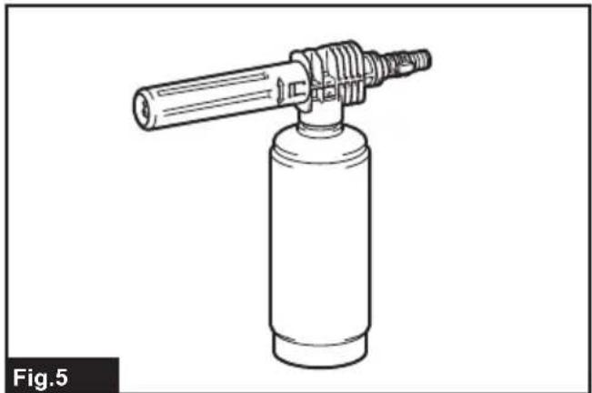
natural_image
Line drawing of a cylindrical tool emitting vapor, labeled Fig.5 (no text or symbols on the diagram itself)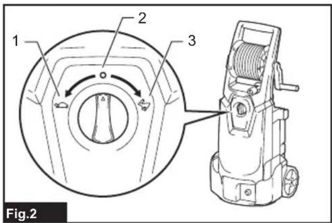
text_image
1 2 3 Fig.2
text_image
1 2 3 Fig.6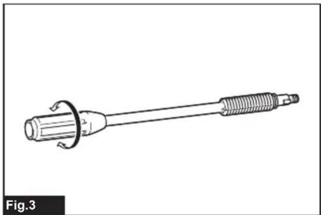
natural_image
Technical line drawing of a mechanical tool or connector with threaded end and flange (no text or symbols)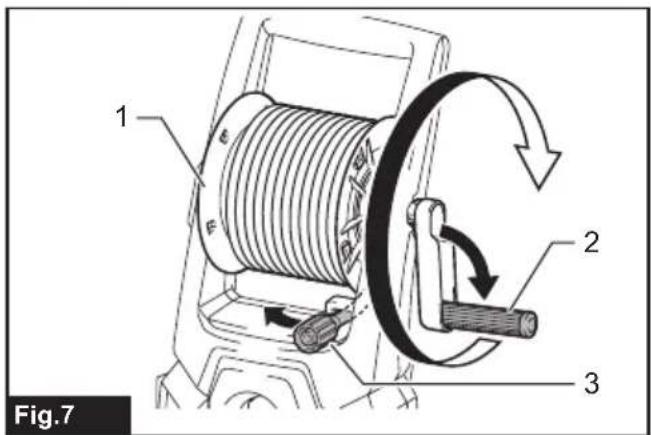
text_image
1 2 3 Fig.7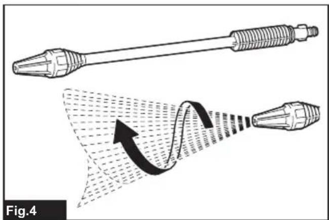
natural_image
Technical illustration of a mechanical tool with a magnified view showing internal flow or stress distribution (no text or symbols)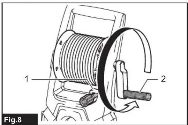
text_image
1 2 Fig.8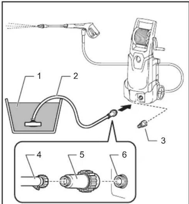
text_image
Technical diagram of a spray gun system with labeled components including water displacement, hose, and valve assemblyFig.9

text_image
Fig.12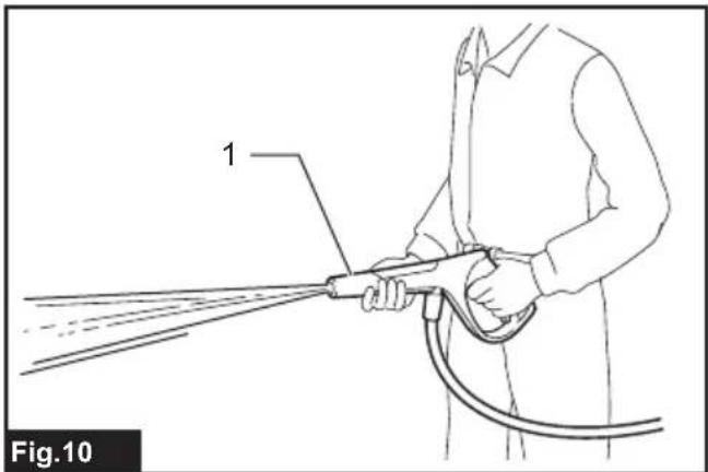
natural_image
Line drawing of a person using a spray gun with a tool, labeled '1' and 'Fig.10' (no text or symbols on the diagram itself)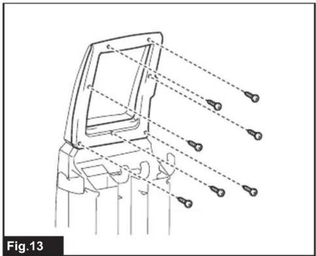
natural_image
Technical line drawing of a mechanical component with multiple screw holes and dashed alignment lines (no text or symbols)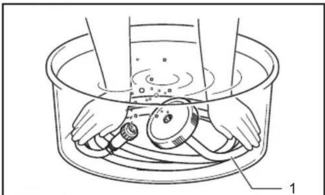
natural_image
Line drawing of a person washing a basin with a device inside (no text or symbols)Fig.11
text_image
1 2 Fig.14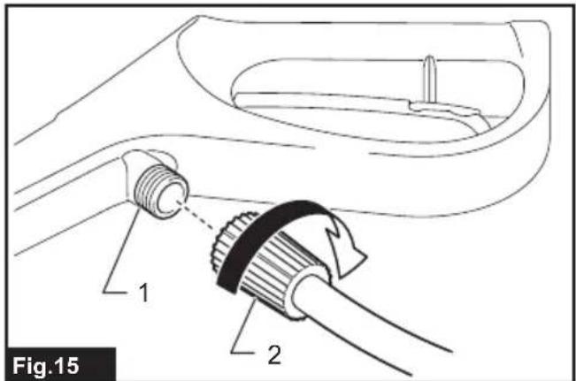
text_image
Fig.15 1 2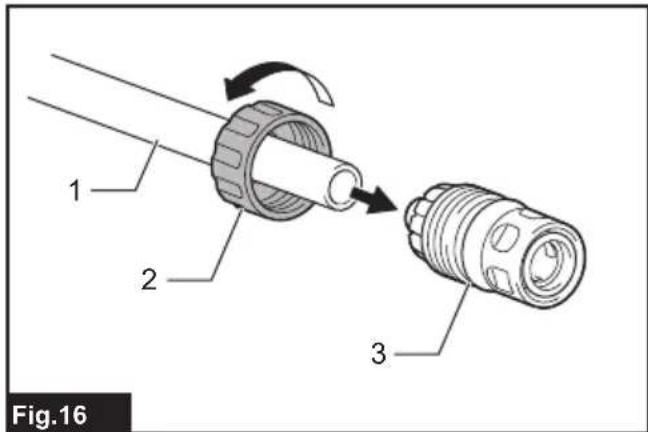
text_image
1 2 3 Fig.16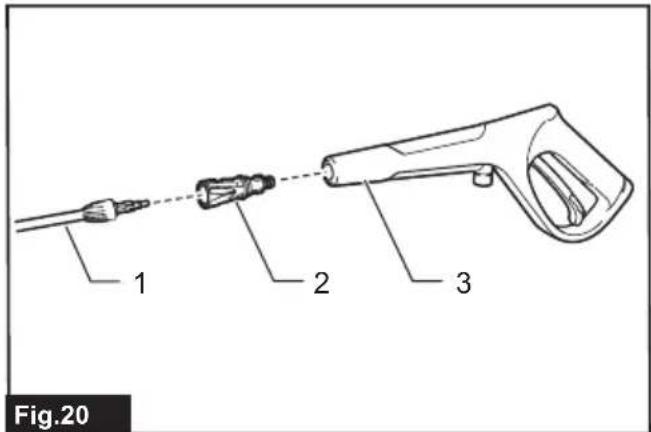
text_image
Fig.20 1 2 3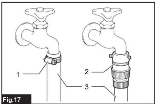
text_image
Fig.17 1 2 3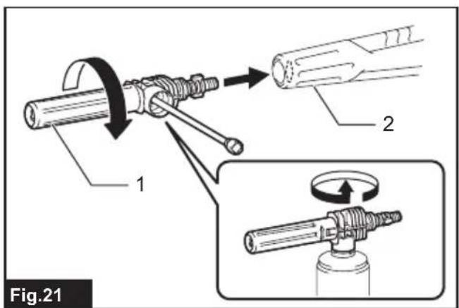
text_image
Fig.21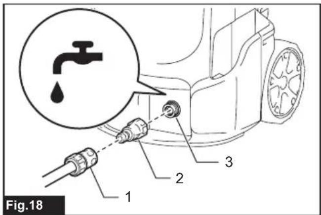
text_image
Fig.18 1 2 3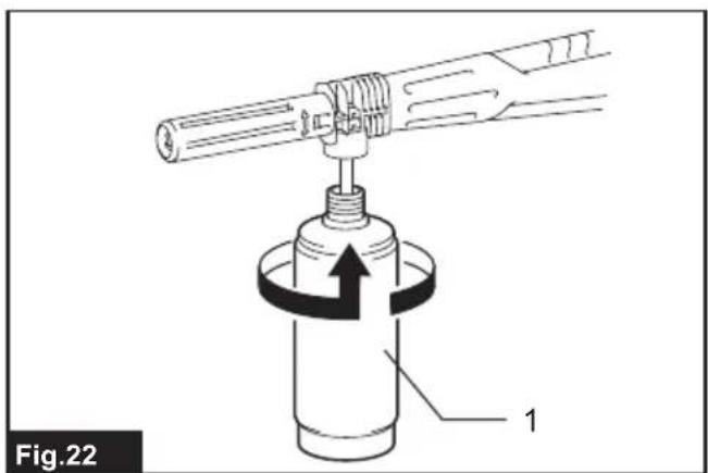
text_image
Fig.22 1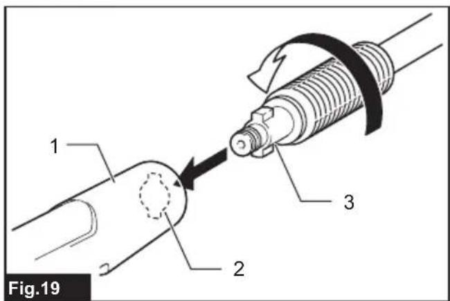
text_image
Fig.19 1 2 3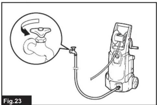
natural_image
Diagram of a mechanical device connected to a faucet, with an inset showing a faucet mechanism (no text or symbols present)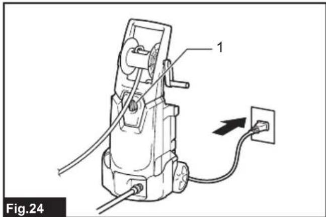
text_image
Fig.24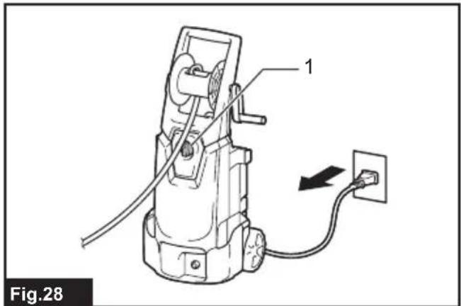
text_image
Fig.28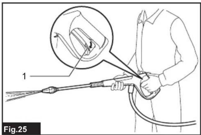
text_image
1 Fig.25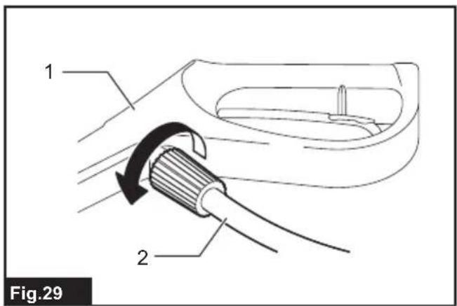
text_image
1 2 Fig.29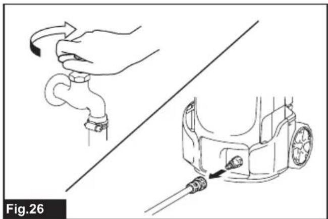
natural_image
Diagram showing hand holding a pipe and cable, connected to a car body with a tool (no text or symbols)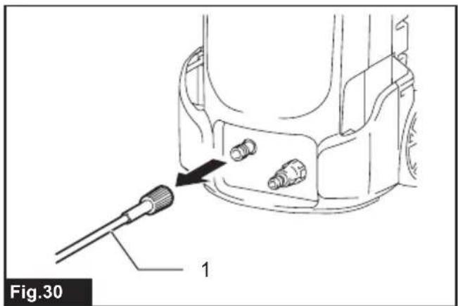
text_image
Fig.30 1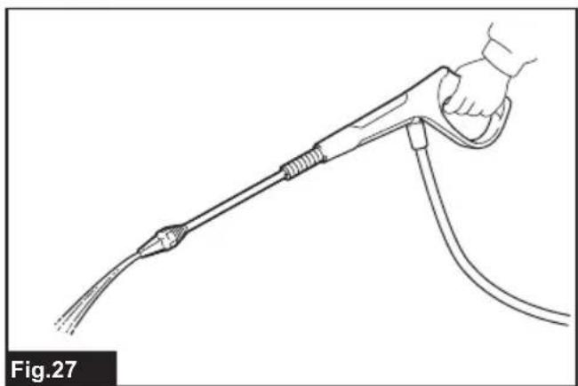
natural_image
Line drawing of a hand holding a handheld electric shock absorber (no text or symbols)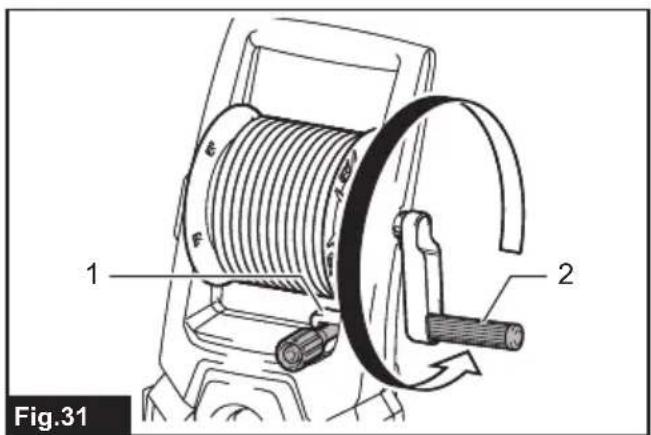
text_image
1 2 Fig.31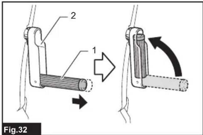
text_image
2 1 Fig.32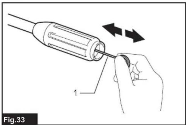
natural_image
Illustration of a hand using a screwdriver to adjust a component (no text or symbols present)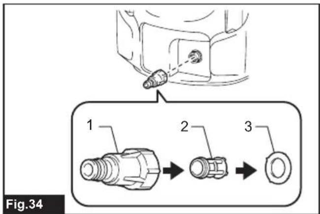
text_image
Fig.34 1 2 3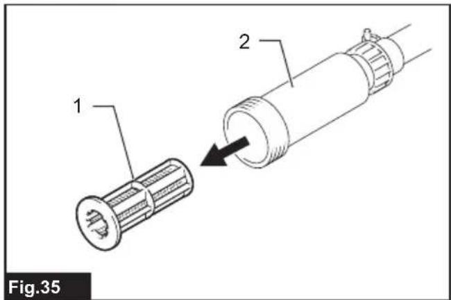
text_image
1 2 Fig.35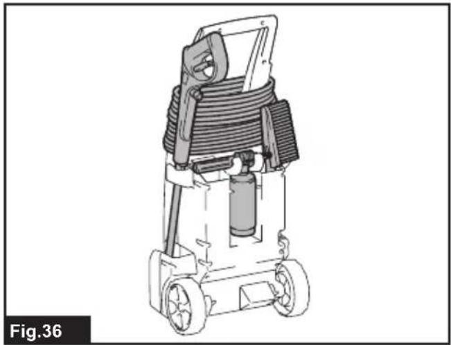
natural_image
Line drawing of a portable electric vehicle with coiled cable and wheels (no text or symbols)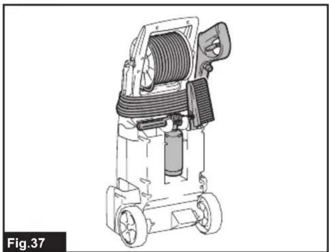
natural_image
Technical line drawing of a mechanical device with hoses and wheels (no text or symbols)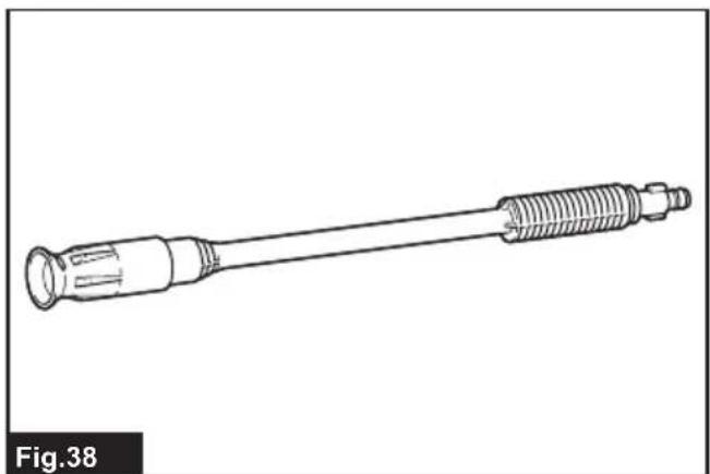
natural_image
Line drawing of a mechanical tool with threaded end and flange (no text or symbols)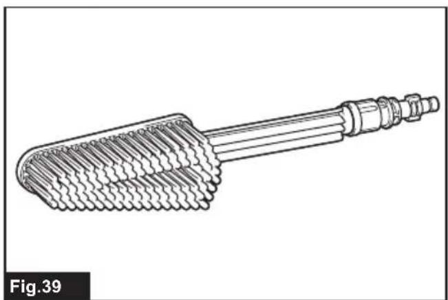
natural_image
Technical line drawing of a mechanical tool or connector with threaded ends and a central shaft (no text or symbols)
natural_image
Line drawing of a coiled hose with a handle and bulb, labeled Fig.40 (no text or symbols on the diagram itself)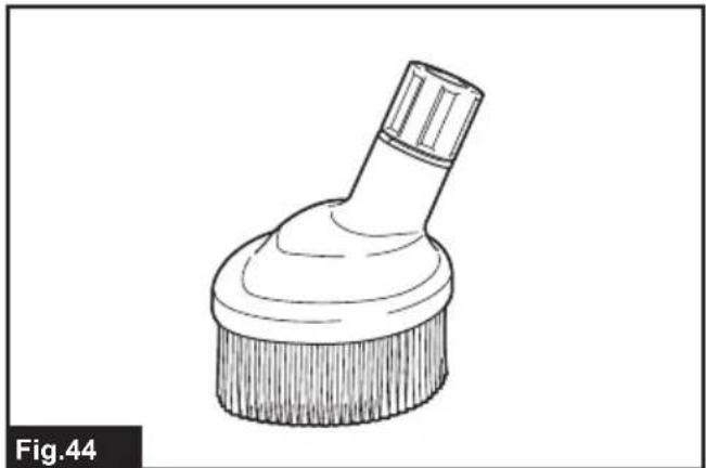
natural_image
Line drawing of a brush tip with a circular base and pointed tip (no text or symbols)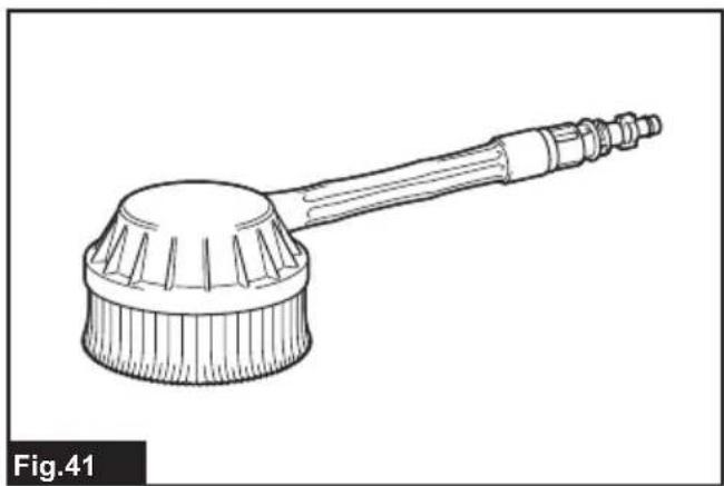
natural_image
Line drawing of a cleaning brush with a pointed tip and handle (no text or symbols)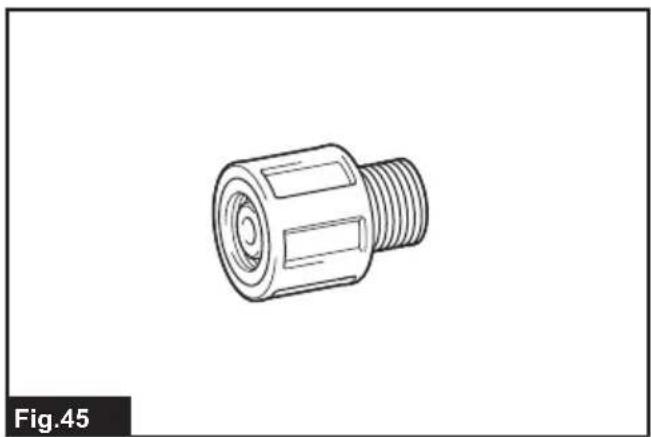
natural_image
Technical line drawing of a threaded connector (no text or symbols)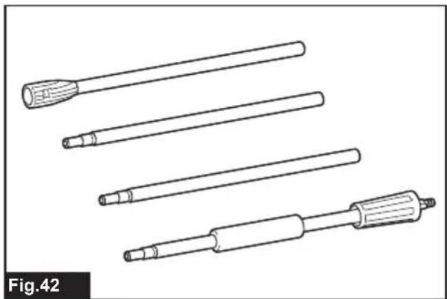
natural_image
Line drawings of four different types of screwdrivers or probes, shown in different orientations (no text or symbols)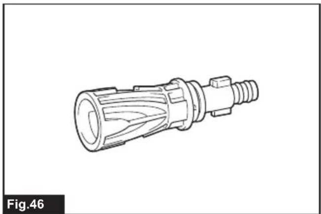
natural_image
Technical line drawing of a mechanical connector (no text or symbols)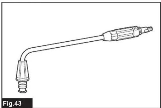
natural_image
Line drawing of a medical or laboratory probe with a pointed tip and threaded end (no text or symbols)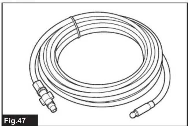
natural_image
Line drawing of a coiled hose with two connectors, labeled Fig.47 (no text or symbols on the diagram itself)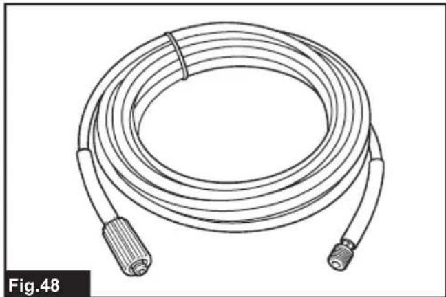
natural_image
Line drawing of a coiled cable with two connectors, labeled Fig.48 (no text or symbols on the diagram itself)WARNING
- Machines shall not be used by children. Children should be supervised to ensure that they do not play with the machine.
- This machine is not intended for use by persons (including children) with reduced physical, sensory, or mental capabilities, or lack of experience and knowledge.
- This machine has been designed for use with the cleaning agent supplied or recommended by the manufacturer. The use of other cleaning agents or chemicals may adversely affect the safety of the machine.
- High pressure jets can be dangerous if subject to misuse. The jet must not be directed at persons, live electrical equipment or the machine itself.
- Do not use the machine within range of persons unless they wear protective clothing.
- Do not direct the jet against yourself or others in order to clean clothes or foot-wear.
- Risk of explosion – Do not spray flammable liquids.
- High pressure cleaners shall not be used by children or untrained personnel.
- High pressure hoses, fittings and couplings are important for the safety of the machine. Use only hoses, fittings and couplings recommended by the manufacturer.
- To ensure machine safety, use only original spare parts from the manufacturer or approved by the manufacturer.
• Always be sure that the tool is switched off and unplugged before carrying out any work on the tool. - Do not use the machine if a supply cord or important parts of the machine are damaged, e.g. safety devices, high pressure hoses, trigger gun.
-
Inadequate extension cords can be dangerous. If an extension cord is used, it shall be suitable for outdoor use, and the connection has to be kept dry and off the ground. It is recommended that this is accomplished by means of a cord reel which keeps the socket at least 60 mm above the ground.
-
Always switch off the mains disconnecting switch when leaving the machine unattended.
- Comply with the requirements of the local water supply company.
• For European countries:
According to EN12729 (BA), the appliance can also be connected to the mains drinking water supply if a backflow preventer valve with drain facility is installed in the supply hose.
SPECIFICATIONS
| Model: HP351 HP401 | |||
| Max. feed volume 7.0 l/min 7.5 l/min | |||
| Water flow rate 5.5 l/min 6.0 l/min | |||
| Max. permissible pressure 12 MPa (120 bars) 13 MPa (130 bars) | |||
| Working pressure High mode 10 | MPa (100 bars) 11 MPa (110 bars) | ||
| Low mode - | 8 MPa (80 bars) | ||
| Max. feed pressure | 1 MPa (10 bars) | ||
| Max. feed temperature | 40 °C | ||
| Max. suction height | 1.0 m | ||
| Dimensions(L x W x H) | 292 mm x 358 mm x 830 mm | ||
| Weight | 11.0 kg | 12.7 kg | |
| Motor protection | IPX5 | ||
- Due to our continuing program of research and development, the specifications herein are subject to change without notice.
- Specifications may differ from country to country.
• Weight according to EPTA-Procedure 01/2003
Symbols
The followings show the symbols used for the equipment. Be sure that you understand their meaning before use.
| Read the instruction manual. | |
| Take particular care and attention. | |
| DOUBLE INSULATION | |
| Only for EU countriesDo not dispose of electric equipment together with household waste material! In observance of the European Directive, on Waste Electric and Electronic Equipment and its implementation in accordance with national law, electric equipment that have reached the end of their life must be collected separately and returned to an environmentally compatible recycling facility. |
Do not direct the jet at people including yourself, animals, and live electrical equipments.

Not suitable for connection to the potable water mains.
Intended use
This tool is intended for cleaning stubborn dirt by using water jet. This tool is intended for household use.
Power supply
The tool should be connected only to a power supply of the same voltage as indicated on the nameplate, and can only be operated on single-phase AC supply. They are double-insulated and can, therefore, also be used from sockets without earth wire.
For public low-voltage distribution systems of between 220 V and 250 V
Switching operations of electric apparatus cause voltage fluctuations. The operation of this device under unfavorable mains conditions can have adverse effects to the operation of other equipment. With a mains impedance equal or less than 0.25 Ohms it can be presumed that there will be no negative effects. The mains socket used for this device must be protected with a fuse or protective circuit breaker having slow tripping characteristics.
Noise
The typical A-weighted noise level determined according to EN60335-2-79:
Model HP351
Sound pressure level ( L_pA ): 72 dB(A)
Uncertainty (K) : 3.8 dB(A)
Model HP401
Sound pressure level ( L_pA ): 76 dB(A)
Uncertainty (K) : 2.4 dB(A)
The noise level under working may exceed 80 dB (A).

WARNING: Wear ear protection.
Vibration
The vibration total value (tri-axial vector sum) determined according to EN60335-2-79:
Model HP351
Vibration emission ( a_h ): 4.11 m/s ^2
Uncertainty (K) : 1.5 m/s ^2
Model HP401
Vibration emission ( a_h ): 4.86 m/s ^2
Uncertainty (K) : 1.5 m/s ^2
NOTE: The declared vibration total value(s) has been measured in accordance with a standard test method and may be used for comparing one tool with another.
NOTE: The declared vibration total value(s) may also be used in a preliminary assessment of exposure.

WARNING: The vibration emission during dual use of the power tool can differ from the declared value(s) depending on the ways in which a tool is used especially what kind of workpiece processed.

WARNING: Be sure to identify safety measures to protect the operator that are based on animation of exposure in the actual conditions of the (taking account of all parts of the operating cycle such as the times when the tool is switched and when it is running idle in addition to the longer time).
EC Declaration of Conformity
For European countries only
The EC declaration of conformity is included as Annex A to this instruction manual.
SAFETY WARNINGS

WARNING: Read all safety warnings and instructions. Failure to follow the warnings and tructions may result in electric shock, fire and/orious injury.
Save all warnings and instructions for future reference.
Work area safety
- Keep operating area clear of all persons.
- Do not overreach or stand on unstable supports. Keep good footing and balance at all times.
- Always place the high pressure washer body on a level and stable surface. Avoid areas where the ejected water will run or pool.
- Before cleaning, check the surroundings and objects to be cleaned. High pressure jets can scrape away paint or other surface treatments including toxic chemicals. Take the preventive measures if necessary.
- Be careful not to trip over by the cord or hose of the high pressure washer. Always be aware of the configuration of the cord and hose during operation.
- During use, a small amount of water will come out from the bottom of the high pressure washer. Avoid locating the high pressure washer in the areas where you don't want to wet.
Personal safety
- To protect against the jet and objects by the jet, operators should wear appropriate clothing such as safety boots, safety gloves, safety helmets with visors, hearing protection, etc.
- Do not use the high pressure washer within range of persons unless they wear protective clothing.
- To reduce the risk of injury, close supervision is necessary when the product is used near children.
- Water that has flowed through backflow preventer is considered to be non-potable.
Electrical safety
- Never use the high pressure washer outdoors in the rain.
- Never touch the mains plug and/or socket with wet hands.
- Do not use the machine if the supply cord or important parts of the machine are damaged, e.g. safety devices, high pressure hoses, or the trigger gun.
- Plug must match the outlet. Never modify the plug in any way. Do not use any adapter plug with grounded tools. Unmodified plug and matching outlet will reduce risk of the electric shock.
-
Inadequate extension cords can be dangerous. If an extension cord is used, it shall be suitable for outdoor use, and the connection has to be kept dry and off the ground. It is recommended that this is accomplished by means of a cord reel which keeps the socket at least 60 mm above the ground.
-
Note the following when using extension cords:
-
Use only extension cords that are intended for outdoor use.
- Use only extension cords with an electrical rating equal to or higher than the rating of the product.
- Do not use damaged extension cords.
- Examine extension cords before use and replace if damaged.
- Do not abuse extension cords and do not yank on cords to disconnect them.
-
Keep cords away from heat and sharp edges.
• Always disconnect the extension cord from the receptacle before disconnecting the product from the extension cord. -
The electric supply connection shall be made by a qualified electrician and comply with IEC 60364-1. It is recommended that the electric supply to this machine should include either a residual current device that will interrupt the supply if the leakage current to earth exceeds 30 mA for 30 ms or a device that will prove the earth circuit.
Power tool use and care
- Read all the instructions before using the product.
- Know how to stop the high pressure washer and bleed pressures quickly. Be thoroughly familiar with the controls.
- High pressure jets can be dangerous if misused. The jet must not be directed at people, live electrical equipment, or the machine itself.
- This machine is not intended for use by persons (including children) with reduced physical, sensory, or mental capabilities, or lack of experience and knowledge.
- Children should be supervised to ensure that they do not play with the appliance.
- Do not spray flammable and/or toxic liquids. This may cause an explosion, intoxication, or damage to the machine.
- Do not direct the jet against yourself or others in order to clean clothes or foot-wear.
- High-pressure hoses, fittings and couplings are important for the safety of the machine. Use only hoses, fittings and couplings recommended by the manufacturer.
- Follow the instructions when changing accessories.
- Keep handles dry, clean, and free of oil or grease.
- Stay alert – watch what you are doing.
- Do not operate the product when fatigued or under the influence of alcohol or drugs.
- Do not run the high pressure washer without water for longer than one minute. It will damage the motor, resulting in malfunction.
-
Always turn off the power and shut off the water mains when leaving the high pressure washer unattended.
-
Be wary of the kickback. The trigger gun recoils when the high pressure jet is ejected from the nozzle. Hold the trigger gun firmly to prevent accidental injuries.
- Check for damaged or worn parts before use. Also make sure that the hose is properly connected and there is no leakage during operation. Operating the machine with functional defects may cause an accident.
- This machine has been designed for use with the cleaning agent supplied or recommended by the manufacturer. The use of other cleaning agents or chemicals may adversely affect the safety of the machine.
- Do not pull the cord and/or hose to move the high pressure washer body. This will damage the cord, hose, and connecting parts and result in a short circuit or functional defects.
- Do not put heavy objects on the hose or let vehicles drive over it.
- Always discharge the residual pressure in the trigger gun before disconnecting the hose.
- When connecting the hose to the water mains, observe the instructions of your local water-works department or company.
- Follow the maintenance instructions specified in the manual.
- To ensure machine safety, use only original spare parts from the manufacturer or approved by the manufacturer.
- Have your high pressure washer serviced by a qualified repair person using only identical replacement parts. This will ensure that the safety of the high pressure washer is maintained.
- In case of breakdown or malfunction of the high pressure washer, immediately switch it off and remove the mains plug. Contact your local dealer or service center.
Service
SAVE THESE INSTRUCTIONS.
WARNING: DO NOT let comfort or familiarity with product (gained from repeated use) replace strict adherence to safety rules for the subject product.
MISUSE or failure to follow the safety rules stated in this instruction manual may cause serious personal injury.
FUNCTIONAL DESCRIPTION
⚠️CAUTION: Always be sure that the tool is switched off and unplugged before adjusting or checking function on the tool.
Power switch
NOTICE: Do not turn the power switch forcibly.
This may cause the switch to malfunction.
For the HP351
▶ Fig.1: 1. OFF position 2. ON position
Turn the power switch clockwise to switch on the high pressure washer.
For the HP401
Turn the power switch clockwise or counterclockwise depending on the pressure level. Turn the power switch clockwise for high pressure mode, counterclockwise for low pressure mode.
▶ Fig.2: 1. Low pressure mode 2. OFF position 3. High pressure mode
Nozzle functions
NOTE: The standard nozzles vary depending on the country. Also refer to the OPTIONAL ACCESSORIES section for other nozzles.
Vario-Power spray lance
▶ Fig.3
Jet pressure can be adjusted by rotating the nozzle.
⚠️CAUTION: When adjusting the jet pressure, do not rotate the nozzle while pulling it toward the trigger gun. The nozzle may come off from the trigger gun and cause a personal injury.
Dirt blaster
▶ Fig.4
A spiral jet is ejected. Suitable for removing stubborn dirt.
NOTICE: Do not use the dirt blaster to clean fragile surfaces such as windows or car bodies.
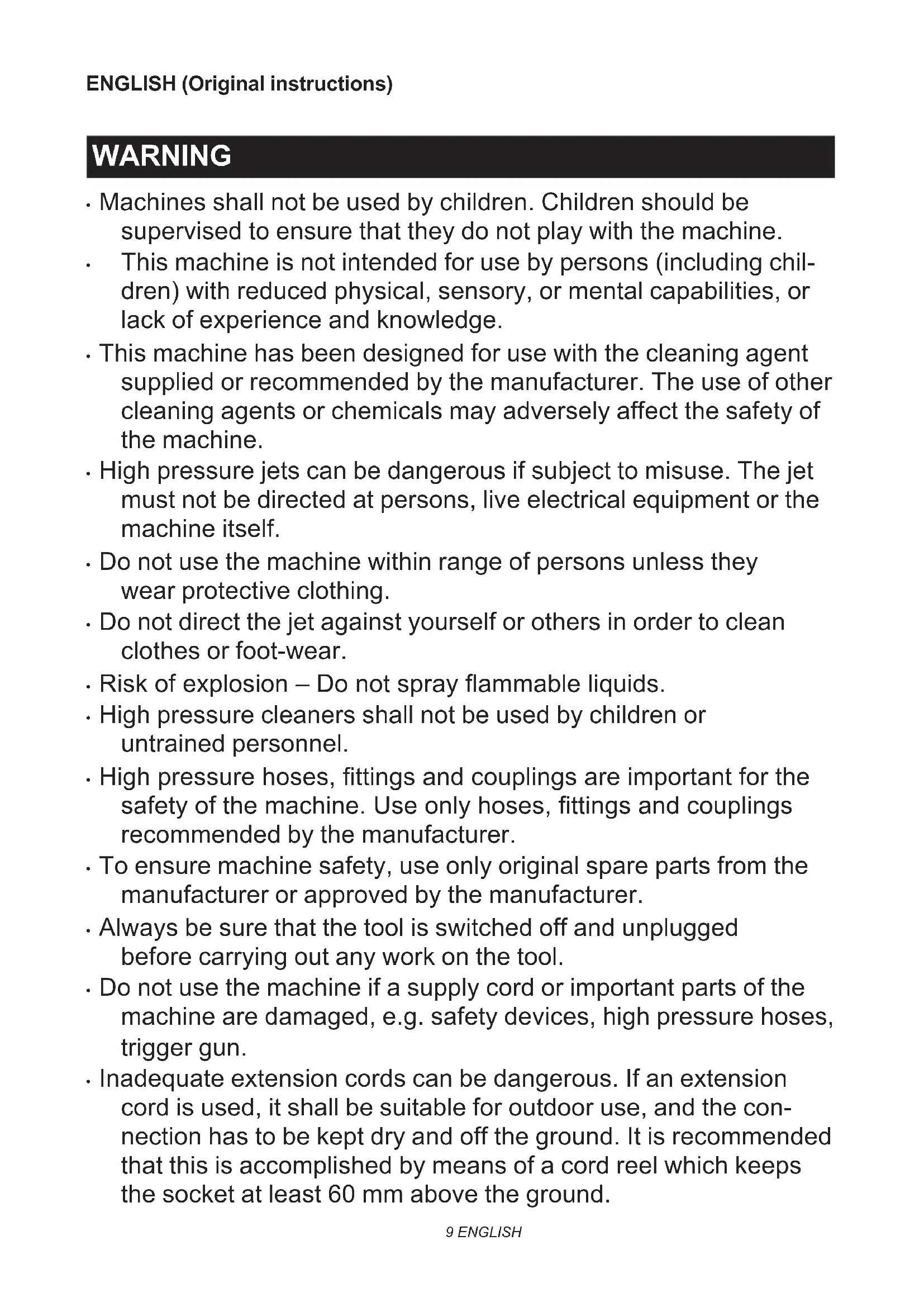
Foam nozzle
▶ Fig.5
Detergent can be sprayed as foam.
Trigger operations
Pull the trigger to eject a water jet. The jet continues as long as the trigger is squeezed.
The trigger can be locked for safe handling of the trigger gun. To lock the trigger, pull out the stopper and hook it to the groove on the grip.
▶ Fig.6: 1. Trigger 2. Stopper 3. Groove
NOTICE: To avoid mechanical error in the pressure switch, always leave a two-second interval between trigger operations.
Safety valve
This appliance is equipped with a safety valve that prevents undue overpressure. When the trigger is released, the valve opens and the water recirculates through the pump inlet.
⚠️ CAUTION: Do not tamper with or adjust the safety valve setting.
Hose reel
For the HP401 only
To unreel the hose, take the end of the hose out of the catch first. Unfold the handle and turn it clockwise.
Always unreel the hose all the way to the end when operating the high pressure washer.
▶ Fig.7: 1. Hose reel 2. Handle 3. End of the hose
When storing the hose, turn the handle counterclockwise and fix the end of the hose.
▶ Fig.8: 1. Catch 2. Handle
Supplying water from a tank/reservoir
Optional accessory
You can supply water from a tank or reservoir instead of a faucet.
Replace the water hose connector with the suction hose set (optional accessory). When connecting the suction hose set, disconnect the filter case from the hose and attach it to the inlet on the high pressure washer. Then, connect the hose to the filter case.
▶ Fig.9: 1. Tank/reservoir 2. Suction hose set 3. Water hose connector 4. Hose 5. Filter case 6. Inlet on the high pressure washer
NOTICE: Always use Makita's suction hose set.
NOTICE: Always keep 1.0 m (3.28 ft) or less in height between the inlet on the high pressure washer and the water surface. Otherwise, the high pressure washer will be unable to take the water up into the pump.
To introduce water into the hose, remove the nozzle from the trigger gun and switch on the high pressure washer while the trigger is squeezed. Once water is ejected stably from the trigger gun, release the trigger and attach the nozzle for your purpose.
▶ Fig.10: 1. Trigger gun
NOTE: When water is not ejected, detach the suction hose set and soak it in water. Then reconnect it to the high-pressure washer.
▶ Fig.11: 1. Suction hose set
ASSEMBLY
⚠️CAUTION: Always be sure that the tool is switched off and unplugged before carrying out any work on the tool.
Assembling the carrying handle
For the HP351 only
- Join the front and rear halves of the handle by aligning the screw holes on the high pressure washer body.
▶ Fig.12: 1. Front half of the handle 2. Rear half of the handle 3. High pressure washer body - Secure the carrying handle with screws(7 pcs).
▶ Fig.13
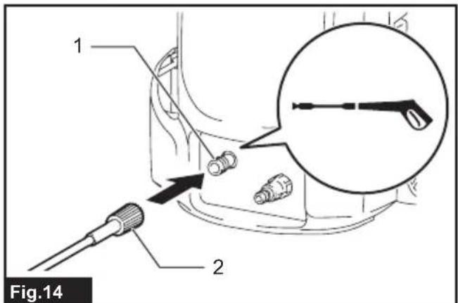
Connecting the high-pressure hose
For the HP351 only
Connect the high-pressure hose to the outlet (with the gun marking). Turn the nut on the high-pressure hose clockwise while screwing it onto the screw thread of the outlet.
▶ Fig.14: 1. Outlet 2. Nut
⚠CAUTION: Make sure that the high-pressure hose is securely connected. A loose connection may blow the high-pressure hose off, resulting in a personal injury.
Attaching the trigger gun
Connect the high-pressure hose to the inlet on the trigger gun. Turn the nut on the high-pressure hose clockwise while screwing it onto the screw thread on the inlet.
▶ Fig.15: 1. Inlet 2. Nut
⚠️CAUTION: Make sure that the high-pressure hose is securely connected. A loose connection may blow the high-pressure hose off, resulting in a personal injury.
Connecting to a faucet
⚠️CAUTION: Always use a pressure-resistant water hose with ∅13 mm or larger diameter and connect to the faucet using a proper fittings. Otherwise, the water hose and/or the fitting may break and cause personal injury.
NOTICE: Use a pressure-resistant water hose as short as possible. The amount of intake water should be higher than the max feed volume of the pump.
NOTICE: If you connect to the mains for drinking water, use a backflow preventer valve which meets the regulations in your region.
Prepare a pressure-resistant water hose. Attach the coupling sleeve to one end and connect the other end to the faucet as follows.
- Remove the nut on the coupling sleeve and pass the pressure-resistant water hose through the nut. Insert the end of the hose into the coupling sleeve and then tighten the nut.
▶ Fig.16: 1. Pressure-resistant water hose 2. Nut of the coupling sleeve 3. Coupling sleeve
NOTE: If you connect the pressure-resistant water hose to the faucet using a coupling sleeve, attach it to the both ends of the hose.
- Connect the pressure-resistant water hose to the faucet. Apply a suitable fitting such as hose band or water tap joint to secure the hose end with the faucet.
▶ Fig.17: 1. Hose band 2. Water tap joint 3. Pressure-resistant water hose
NOTE: The fitting depends on the shape of the faucet to which you connect. Prepare a suitable commercially-bought fitting.
- Attach the water hose connector to the inlet (with the faucet marking) and then insert the coupling sleeve.
▶ Fig.18: 1. Coupling sleeve 2. Water hose connector 3. Inlet on the high pressure washer
Connecting/disconnecting the nozzle
⚠️ CAUTION: Always lock the trigger when connecting/disconnecting the nozzle.
Insert the end of the nozzle into the slot on the trigger gun and turn it in the direction of the arrow as shown in the figure. To disconnect, turn the nozzle in the reverse direction while pressing it toward the trigger gun.
▶ Fig.19: 1. Trigger gun 2. Slot 3. End of the nozzle
Some optional nozzles require the connecting joint (optional accessory) to attach to the trigger gun. Attach the connecting joint to the trigger gun in the same way as the nozzle.
▶ Fig.20: 1. Nozzle 2. Connecting joint 3. Trigger gun
NOTE: The connecting joint is needed when using the nozzles included with another model, HP-350 or HP-400.
Connecting the foam nozzle
CAUTION: Always lock the trigger when connecting/disconnecting the nozzle.
Prepare a detergent before using the foam nozzle.
- Remove the nozzle from the tank by rotating the nozzle counterclockwise. Attach the nozzle to the trigger gun.
▶ Fig.21: 1. Nozzle 2. Trigger gun - Pour the detergent into the tank and install it to the nozzle.
▶ Fig.22: 1. Tank
NOTICE: Always use neutral detergent. Acidic or alkaline detergent may damage the tank or nozzle.
OPERATION
WARNING: Do not touch the water jet or direct it toward yourself or others. The water jet is dangerous and can hurt you or others.
WARNING: When shooting the water jet, never hold the object that you are cleaning or place your hands and feet near the water jet.
⚠️CAUTION: Stay alert to the rebound of the water jet and blown objects. Do not bring the nozzle to the object closer to 30 cm.
⚠️CAUTION: Do not run the high pressure washer without water for longer than 1 minute.
⚠️CAUTION: Do not operate the high pressure washer for a extended period of time. This may cause overheating or fire. Also, long-term use may cause vibration disorder.
CAUTION: Be aware of the direction of the wind. If the detergent gets into your eyes or mouth, rinse with fresh water immediately and seek medical attention if necessary.
NOTICE: Avoid using the high pressure washer for longer than 1 hour. After using it for 1 hour, leave a same length of intermission.
-
Connect the end of the high-pressure hose to the trigger gun. For the HP351, connect the other end to the high pressure washer. For the HP401, unreel the hose all the way to the end.
-
Connect the high pressure washer to the faucet and then open the faucet.
▶ Fig.23
NOTICE: To protect the mechanism of the high pressure washer, do not use water hotter than 40°C.
- Plug the high pressure washer into the mains and switch it on.
▶ Fig.24: 1. Power switch
- To eject a water jet, unlock the stopper and squeeze the trigger. The jet continues as long as the trigger is squeezed.
▶ Fig.25: 1. Stopper
⚠️CAUTION: Hold the trigger gun firmly. The trigger gun recoils when you pull the trigger.
CAUTION: Always hold the trigger gun by the grip and barrel when cleaning. While the motor is running, do not touch any part of the high pressure washer body other than the carrying handle and power switch.
NOTICE: Be careful not to pull the trigger gun forcibly during operation. It may cause the high pressure washer to fall over.
After operating
CAUTION: After operating, always perform the procedure described in this manual. Residual pressure in the trigger gun or high pressure washer can cause personal injury or damage to the pump inside.
- After operating, leave the power switch on.
- Close the faucet and disconnect the water hose from the high pressure washer.
▶ Fig.26
- Squeeze the trigger until the remaining water in the high pressure washer is discharged.
Do not run the motor for longer than 1 minute.
▶ Fig.27
- Switch off the high pressure washer and unplug it from the mains.
▶ Fig.28: 1. Power switch - Disconnect the high-pressure hose from the trigger gun.
▶ Fig.29: 1. Trigger gun 2. High-pressure hose
For the HP351 only
Disconnect the high pressure hose from the high pressure washer.
▶ Fig.30: 1. High pressure hose
For the HP401 only
- Reel the hose and fix the end of the hose.
▶ Fig.31: 1. Catch 2. Handle - Fold the handle into the reel arm while pulling the handle to the direction of the arrow as shown in the figure.
▶ Fig.32: 1. Handle 2. Reel arm
NOTICE: To prevent the high-pressure hose from being damaged, remove the remaining water in the hose before storing.
CAUTION: Always be sure that the tool is switched off and unplugged before attempting to perform inspection or maintenance.
NOTICE: Never use gasoline, benzine, thinner, alcohol or the like. Discoloration, deformation or cracks may result.
Cleaning the nozzle
Use the cleaner pin to remove dirt from or unclog the nozzle.
▶ Fig.33: 1. Cleaner pin
NOTICE: Do not remove dirt or debris forcibly. This may result in personal injury or damage to the ejection hole causing deviated jet angles or poor performance.
Cleaning the filter
Detach the water hose connector and remove dirt and debris from the inside of the filter.
▶ Fig.34: 1. Water hose connector 2. Filter 3. Sealing ring
When using the suction hose set (optional accessory), take the filter out of the filter case and remove dirt and debris.
▶ Fig.35: 1. Filter 2. Filter case
NOTE: To maintain the optimal performance, clean the filter periodically.
Storage
Reel the hose and cord. Put the trigger gun and nozzles in the pockets.
HP351
▶ Fig.36
HP401
▶ Fig.37
CAUTION: Always store in an indoor location where the temperature does not go below freezing. If the high pressure washer freezes and malfunctions, contact your local service center for repairs.
CAUTION: Always use the carrying handle when moving the high pressure washer. Do not carry it by the hose or cord. The hose or cord may be damaged.
CAUTION: Do not carry the high pressure washer with the hose and/or cord unreeled. The extended hose or cord may be damaged or entangled with other objects, resulting in personal injury or breakage.
To maintain product SAFETY and RELIABILITY, repairs, any other maintenance or adjustment should be performed by Makita Authorized or Factory Service Centers, always using Makita replacement parts.
TROUBLESHOOTING
Before asking for repairs, conduct your own inspection first. If you find a problem that is not explained in the manual, do not attempt to dismantle the tool. Instead,
ask Dolmar Authorized Service Centers, always using Dolmar replacement parts for repairs.
| State of abnormality Probable cause | (malfunction) Remedy | |
| The washer does not start. | No electricity | Connect the plug to the mains. Also check if electricity is being supplied to the mains. |
| The switch is not turned on. Turn on the switch. | ||
| Residual pressure in the pump Pull the trigger. | ||
| Damaged cord or electric circuit Contact an authorized service center for repairs. | ||
| No water jet / weak water jet | No water supply | Make sure that the faucet is open. If using the suction hose set, introduce water into the hose. |
| Poor water supply Turn on the faucet. | ||
| Poor water hose connection Check the connection between the water hose and the faucet and inlet on the high pressure washer. | ||
| Clogged hose, filter, or nozzle Unclog the hose, filter, or nozzle. | ||
| Air is blocking the flow of water. | Turn off the switch and then turn it on again while squeezing the trigger. | |
| Damaged or worn nozzle | Replace the nozzle. | |
| Pump or valve malfunction | Contact an authorized service center for repairs. | |
| Unstable water jet. | Clogged nozzle | Unclog on the ejection hole of the nozzle using the cleaner pin. |
| Poor water suction | Check the water hose starting from the faucet for any leakage or clogs. Turn on the faucet. | |
| The water is too hot. | Supply cooler water. | |
| Valve malfunction | Contact an authorized service center for repairs. | |
| Abnormal sound. | The water is too hot. | Supply cooler water. |
| Air is stuck in the pump. Contact an authorized service center for repairs. | ||
| Water/oil leakage. | Poor connection | Check the connection between the high pressure hose and the trigger gun and high pressure washer. |
| Worn out sealings Contact an authorized service center for repairs. | ||
| The pump does not run even though the motor sound is heard. | Unsuitable extension cord. | Use an extension cord suitable for the rating of the product. |
OPTIONAL ACCESSORIES
⚠️CAUTION: These accessories or attachments are recommended for use with your Dolmar tool specified in this manual. The use of any other accessories or attachments might present a risk of injury to persons. Only use accessory or attachment for its stated purpose.
If you need any assistance for more details regarding these accessories, ask your local Dolmar Service Center.
NOTE: Some items in the list may be included in the tool package as standard accessories. They may differ from country to country.
Spray lance
▶ Fig.38
Jet width can be adjusted from 0^ to 25^ by rotating the front end of the nozzle.
⚠️CAUTION: When adjusting the jet width, do not rotate the nozzle while pulling it toward the trigger gun. The nozzle may come off from the trigger gun and cause a personal injury.
Washing brush (long)
▶ Fig.39
A nozzle equipped with a brush. Useful for washing out dirt while scrubbing with brush.
Suction hose set
▶ Fig.40
Replace the water hose with this set to supply water from a tank or reservoir.
Rotating wash brush
▶ Fig.41
Three brushes inside rotate slowly when ejecting the jet. Suitable for cleaning light dirt on a exterior wall, car body, bath tub, etc.
Lance extension
▶ Fig.42
Pipes to extend the length of the trigger gun. Three different lengths are available by changing the number of the pipes to be used.
Under body spray lance
▶ Fig.43
An extra long spray lance with angled nozzle. Best for cleaning hard-to-reach areas such as car under body and roof gutter.
⚠️CAUTION: Do not use the under body spray lance with the lance extension.
Splash guard
▶ Fig.44
Reduces splash back when cleaning corners with the dirt blaster.
Swivel joint
▶ Fig.45
Prevents the high-pressure hose from being twisted.
Connecting joint
▶ Fig.46
A joint to connect with a nozzle from other model.
NOTE: The connecting joint is needed when using the nozzles included with another model, HP-350 or HP-400.
Pipe-cleaning set (10 m/15 m)
▶ Fig.47
For cleaning and unclogging plumbing and downpipes.
CAUTION: Pay particular attention to the water jet when using the pipe cleaning set. Highly intense water jet is ejected backward.
Extension high-pressure hose (5 m/8 m/10 m)
▶ Fig.48
Extension hose to connect the high pressure washer body with the trigger gun.
AVERTISSEMENT
▶ Fig.8: 1. Cran 2. Poignée
▶ Fig.11: 1. Ensemble du tuyau d'aspiration
ASSEMBLAGE
▶ Fig.22: 1. Réservoir
▶ Fig.30: 1. Tuyau haute pression
▶ Fig.31: 1. Cran 2. Poignée
▶ Abb.25: 1. Stopper
VEILIGHEIDSWAAR- SCHUWINGEN

▶ Fig.6: 1. Trekker 2. Stopper 3. Groef
OPTIONELE ACCESSOIRES
▶ Fig.1: 1. FRA-position 2. TIL-position
▶ Fig.25: 1. Stopper
▶ Fig.33: 1. Rensepind