MIC 70 - Tractor Kärcher - Free user manual and instructions
Find the device manual for free MIC 70 Kärcher in PDF.

User questions about MIC 70 Kärcher
0 question about this device. Answer the ones you know or ask your own.
Ask a new question about this device
Download the instructions for your Tractor in PDF format for free! Find your manual MIC 70 - Kärcher and take your electronic device back in hand. On this page are published all the documents necessary for the use of your device. MIC 70 by Kärcher.
USER MANUAL MIC 70 Kärcher
natural_image
Side view of a KARCHER utility vehicle with visible license plate number 40 and no text or symbols on the vehicle itself.Deutsch 3
English 45
Français 87
Italiano 130
Español 173
Português 216
Nederlands 259
Ελληνικά 301
Inhalt
Hinweis
①Hauptschalter
②Batterie getrennt
③Batterie verbunden
①Elektrische PTO
natural_image
Close-up of a car's front bumper with mesh pattern and three numbered labels (1, 2, 3) pointing to the interior area.①Lenkrad
②Scheibenwischer
①Joystick
① Schalter Tempomat
Tempomat aktivieren
①Kupplungsstecker
②Kupplungsmuffe
③Ring
natural_image
Front view of a vehicle chassis with visible tire tracks and labeled components (no text or symbols beyond labels)①Aufnahmerahmen
natural_image
Interior view of a mechanical or electronic device frame with a central component and mounting holes (no visible text or symbols)natural_image
Close-up of a joystick controller with colored buttons and a handle, labeled with number 1 (no text or symbols on the device itself)①Bedienhebel
natural_image
Top-down view of a vehicle rear bumper with visible headlights, buttons, and structural components (no text or symbols)①Aufnahmerahmen
natural_image
Top-down view of a vehicle's rear front panel with labeled components (no text or symbols beyond labels)①Anhängerkupplung
natural_image
Front view of a tractor with visible structural components and numbered parts (no text or symbols)natural_image
Close-up of a mechanical assembly with a metallic component and a numbered label (1), no readable text or symbols present.natural_image
Close-up of mechanical components with a numbered annotation pointing to a specific part (no readable text or symbols)①Bypassventil

①Ölmessstab
natural_image
Close-up of a mechanical device showing two labeled parts (① and ②) with no visible text or symbols on the main components.①Öleinfülldeckel
natural_image
Close-up of a mechanical device with an inset showing a component inserted into a housing (no visible text or symbols)①Abdeckung Kühlerdeckel
②Kühlerdeckel
①Fahrersitz
②Staubfilter
③Umlufthebel
| Fuse | Consumer | Fuse | Consumer | Fuse | Consumer |
| F015A | Right position lightsRight license plate lightBacklight multinstrument | F1415A | Extra controllerExtra CANSeat heating | F2510A | MAF sensorDisplayExtra brake |
| F025A | Left position lightsLeft license plate lightElectrical PTO front | F1510A | Power supply 3 | F2615A | H1 AC2 pumpSpeed selectionMode switchBrake pressure switchFNR switchReverse buzzerPark brakeFree wheel valveEngine air filterHydraulic oil filterHydraulic oil temp |
| F0310A | Fuse F01Fuse F02 | F1615A | WiperWasher pumpHornDifferential lockDump valve | ||
| F0415A | Hazard lightsInterior light | ||||
| F0530A | Heated windshieldHeated mirrors | F1730A | Float valvesPTO valvesWeight transfer valvesFrontloader lock valve | ||
| F0620A | Electrical PTO frontElectrical PTO rear | ||||
| F0715A | Power supply 1 | F1820A | Air condition | F2710A | Ignition |
| F0830A | Seat compressorStop solenoid pull | F195A | EGR valveEngine diagnostic connector | F285A | Ignition |
| F0920A | Low beamHigh beamSwitch high/low roadlights | F2010A | Cabin 12V socket frontCabin 12V socket rear | F2925A | Engine ECUEngine sensorsFuel pump |
| F1030A | Worklights frontWorklights rearRotating beacon | F2115A | Rocker switch lightsElectrical change valvesFrontloader change valveLoad damping valvesRadio | F3040A | Preheat |
| F1120A | Change valve rearLeak valveLeak valve load platform | F2210A | Control module | F3110A | Diagnostic connectorDisplay |
| F1210A | Power supply 2 | F2310A | Cruise controlBrake lightsReverse pressure switch | F322A | Radio constant feed |
| F1315A | Direction lightsMulti instrumentSpeed indicatorSpeedometer | F247.5A | AlternatorSeat switchFuel pumpRear view camera | F335A | Start indication |
| F3450A | Starter |
①Klemmhebel
②Abdeckung
①Sicherungen
natural_image
Interior view of a vehicle engine bay with visible hoses, springs, and internal components (no text or symbols)drücken.

1.1 Checking the delivery.... 45
1.2 Scope of delivery 45
1.3 Warranty 45
1.4 Accessories and spare parts.... 45
2 Intended use.... 45
2.1 Foreseeable misuse.... 46
2.2 Residual risks.... 46
3 Environmental protection 46
3.1 Disposal 46
3.2 Disposal of the worn out vehicle 46
4 Safety information 46
4.1 Hazard levels 46
4.2 General safety instructions 46
4.3 Safety instructions for driving.... 47
4.4 Diesel engine safety instructions 47
4.5 Additional safety instructions for engines with a diesel particulate filter 47
4.6 Safety instructions on offloading and transport...... 47
4.7 Safety instructions for care and maintenance...... 47
4.8 Additional operating safety instructions 47
4.9 Symbols on the vehicle.... 48
4.10 Position of warning symbols 49
4.11 Safety devices.... 49
5 Batteries / chargers 49
5.1 Warning symbols 49
5.2 Safety instructions 50
5.3 Procedures in the event of unintentional release of battery acid 50
6 Overview of the appliance.... 50
6.1 Front view 50
6.2 View of the side.... 51
6.3 View of the rear.... 51
6.4 Hydraulic and electrical connections.... 51
6.5 Main switch 52
6.6 Driver cabin.... 52
6.7 MIC 70 multifunction display / display.... 54
6.8 Foot room with pedals.... 56
6.9 Multi switch on the steering wheel 57
6.10 Operating consoles.... 57
7 Initial startup 59
7.1 Switching on the main switch.... 59
7.2 Safety check 59
7.3 Setting the driver's seat (standard seat) 60
7.4 Setting the driver's seat (comfort seat, optional)...... 60
7.5 Setting the steering wheel position 60
7.6 Refuelling.... 61
8 Operation....61
8.1 Operating programs....61
8.2 Foot room with pedals.... 62
8.3 Drive mode 62
8.4 Parking the vehicle 63
8.5 Front power lift 63
9 Attachments 64
9.1 Coupling attachments to the vehicle.... 64
9.2 Ballasting the vehicle 65
9.3 Front mounting options 66
9.4 Mounting options at the rear of the vehicle.... 67
9.5 Rear mounting options.... 69
10 Transport 70
10.1 Loading the vehicle.... 70
10.2 Towing the vehicle 70
11 Storage....71
12 Care and maintenance.... 71
12.1 General safety instructions 71
12.2 Service indicator 72
12.3 Maintenance intervals.... 72
12.4 Vehicle maintenance plan (to be carried out by customer) 72
12.5 Lubrication plan.... 74
12.6 Preparing for maintenance work.... 74
12.7 Maintenance work.... 74
12.8 Cleaning....79
12.9 Fuses MIC 70....79
13 Regeneration process MIC 70....80
13.1 Description of regeneration.... 80
13.2 Regeneration
13.3 Regeneration
13.4 Regeneration
13.5 Regeneration
13.6 Regeneration
13.7 Regeneration
13.8 Regeneration
14 Troubleshooting guide 82
14.1 Malfunctions with MIC 70 display.... 83
14.2 Malfunctions without display 83
14.3 Error messages coded.... 84
15 Spare parts list.... 84
15.1 Fuses 84
16 Technical data 85
16.1 Tyres 86
1 General notes
1.1 Checking the delivery
Please report any defects or shipping damage identified on the vehicle when it is handed over directly to your dealer or department store.
1.2 Scope of delivery
1.2.1 MIC 70
- Device carrier with Kubota 48.0 kW diesel engine, hydrostatic drive and diesel particulate filter (DPF).
1.3 Warranty
The warranty conditions issued by our relevant sales company apply in all countries. We shall remedy possible malfunctions on your appliance within the warranty period free of cost, provided that a material or manufacturing defect is the cause. In a warranty case, please contact your dealer (with the purchase receipt) or the next authorised customer service site.
(See overleaf for the address)
1.4 Accessories and spare parts
Only use original accessories and original spare parts.
They ensure that the appliance will run fault-free and safely.
Information on accessories and spare parts can be found at www.kaercher.com.
2 Intended use
This vehicle is suitable for work assignments using various attachments, as well as for towing trailers. The maximum trailer load to be pulled is stated on the type plate and must not be exceeded.
This vehicle is only intended for use in the agricultural sector, in the upkeep of green areas or parks, and for winter service.
No pesticides may be brought out together with the vehicle.
The vehicle must conform to the applicable national regulations if used on public roads.
Only attachments approved by KÄRCHER may be used.
KÄRCHER accepts no liability for accidents or malfunctions from non-approved attachments. Observe the operating instructions from the manufacturer of the attachment. Prior to using the vehicle, read through the operating instructions carefully and familiarise yourself with the operating devices and the other equipment.
Only use the vehicle as intended, as illustrated and described in these operating instructions.
Intended use also includes adherence to the prescribed servicing activities and intervals.
The vehicle and attachments may only be used, maintained and repaired by persons familiar with the vehicle and attachments and the associated hazards.
Observe the general safety regulations and accident prevent guidelines from the legislator. Comply with other generally recognised rules relevant to safety, occupational health and traffic laws.
The operating personnel must:
- Be physically and mentally suitable.
- Have been instructed in the handling of the vehicle and attachments.
- Have read and understood these operating instructions and the operating instructions for any attachments or towed machinery prior to starting work.
- Have provided the operating company with verification of capability to operate the vehicle.
- Be explicitly nominated to operate the vehicle by the operating company.
2.1 Foreseeable misuse
Any use which is not as intended is prohibited. The user shall be liable for hazards that arise as a result of improper usage.
Using the vehicle for other purposes than those described in these instructions is prohibited.
Transporting persons on the vehicle, the loading area or attachments is not allowed.
No modifications must be made to the vehicle.
2.2 Residual risks
Residual risk cannot be excluded, despite proper use and the observance of all given instructions.
⚠ WARNING
Danger due to human error
Indicate these hazards and point out the safety instructions in these operating instructions to persons in the area of the vehicle and attachments.
⚠ WARNING
Danger due to malfunction
Point out to persons in the area of the vehicle and attachments that they should pay particular attention to being able to react immediately in the case of a possible malfunction or an accident, or in the event of system failure.
Dangers could be:
1 Unexpected movements of the attachments and vehicle.
2 Escaping operating fluids due to leaks, bursting of pipes and containers, and similar.
3 Braking as a result of unfavourable ground conditions such as slopes, slipperiness, bumpiness or poor visibility etc.
4 Falling, tripping and similar, when moving around on the vehicle, particularly in wet weather.
5 Fire and explosion hazard caused by the battery and voltage.
6 Risk of fire due to diesel fuel and oils.
7 Human error due to failure to observe the safety instructions.
3 Environmental protection

The packing materials can be recycled. Please dispose of packaging in accordance with the environmental regulations.

Electrical and electronic appliances contain valuable, recyclable materials and often components such as batteries, rechargeable batteries or oil, which - if handled or disposed of incorrectly - can pose a potential threat to human health and the environment. However, these components are required for the correct operation of the appliance. Appliances marked by this symbol are not allowed to be disposed of together with the household rubbish.
Notes on the content materials (REACH)
Current information on content materials can be found at: www.kaercher.com/REACH
3.1 Disposal
- Observe the national regulations at the location.
- Observe company-specific specifications.
- Dispose of any operating and auxiliary materials according to the valid safety data sheets.
3.2 Disposal of the worn out vehicle
Vehicles that are no longer fit for service contain valuable recyclable materials. We recommend you cooperate with a waste management company with regard to the disposal of your vehicle.
4 Safety information
4.1 Hazard levels
△DANGER
- Indication of an imminent threat of danger that will lead to severe injuries or even death.
⚠ WARNING
- Indication of a potentially dangerous situation that may lead to severe injuries or even death.
△CAUTION
- Indication of a potentially dangerous situation that may lead to minor injuries.
ATTENTION
- Indication of a potentially dangerous situation that may lead to damage to property.
4.2 General safety instructions
⚠️ DANGER ● Risk of asphyxiation. Keep packaging film out of the reach of children.
⚠ WARNING • Only use the vehicle for its proper use. Take into account the local conditions and beware of third parties, in particular children, when working. • Persons with reduced physical, sensory or mental capabilities, or those with a lack of experience and knowledge, are only allowed to use the vehicle if they are supervised or have been instructed with respect to using the appliance safely, and understand the resultant dangers involved. • Only people who have been instructed on how to use the vehicle, or have proven their ability to operate it, and have been explicitly instructed to use it, must use the vehicle.
- Children must not operate the vehicle. • Children must
be supervised to prevent them from playing with the vehicle.
⚠️ CAUTION • Safety devices are provided for your own protection. Never modify or bypass safety devices.
4.3 Safety instructions for driving
△ DANGER • Danger of tilting if hill or slope is too steep! Observe the maximum permissible values in the technical data when driving up hills and slopes. • Danger of tilting in case of excessive tilting at side! Observe the maximum permissible values in the technical data when driving lateral to the travel direction. • Danger of tipping on unstable surfaces! Only use the vehicle on stable surfaces.
⚠ WARNING ● Risk of accident due to not adapting speed. Approach corners slowly. ● The list on the risk of overturning is not necessarily comprehensive.
△ CAUTION ● Driver cabins are equipped with air exit slats. Always keep these free from obstructions to ensure sufficient ventilation.
ATTENTION
Ensure free visibility on public roads before use (e.g. fogproof windscreens, mirrors, etc.).
4.4 Diesel engine safety instructions
△ DANGER • Diesel engine: Never operate vehicles with diesel engines in confined spaces. • Danger of poisoning: Do not inhale the exhaust gases. • Never close off the exhaust gas openings. • Never bend down over the exhaust gas opening. Never reach inside the exhaust gas opening. • Always keep away from the drive area. Be aware of the engine after-running time after switching off (3-4 seconds).
4.5 Additional safety instructions for engines with a diesel particulate filter
△ DANGER • The installed engine has a diesel particulate filter (DPF). In normal operating conditions, the driver does not notice anything about the operational sequences for the secondary treatment of the harmful exhaust gases. During the regeneration phase of the diesel particulate filter, the deposited soot particles will be burned and very hot exhaust gases up to 600 °C could escape. Only start the regeneration process in areas that do not pose a fire hazard. For more information on this, it is vital you observe chapter 13 Regeneration process MIC 70!
4.6 Safety instructions on offloading and transport
△DANGER
- The vehicle is not approved for crane loading.
- Do not use a forklift to unload / load the vehicle.
⚠ WARNING
- Observe the weight of the vehicle in order to avoid accidents and injuries, see chapter Technical data. If attachment kits are installed, the weight will be accordingly more.
- Observe the vehicle height when transporting it on a trailer or truck, and secure the vehicle; see chapter Technical data
4.7 Safety instructions for care and maintenance
- Switch off the engine and remove the ignition key before performing cleaning or maintenance work on the vehicle, replacing parts or changing the functionality of the vehicle.
- Repairs may only be carried out by approved customer service sites or staff qualified in this area who are familiar with all relevant safety instructions.
- Adhere to the safety checks according to the applicable local regulations for mobile commercial vehicles.
- The articulated joint, tyres, radiator fins, hydraulic hoses and valves, seals, electrical and electronic components must not be cleaned using a high-pressure cleaner.
4.8 Additional operating safety instructions
Note
The information in this chapter is also provided on a supplementary sheet that must always be carried on the vehicle.
General
The vehicle has a hydrostatic drive and articulated steering. It therefore exhibits driving characteristics that are different to those of a motorcar.
⚠ WARNING
Danger of tipping over
Please note that the driving characteristics of a vehicle with articulated steering differ considerably from those of a motorcar.
Drive around curves at an even and appropriate speed. This applies, in particular, for driving uphill/downhill and driving across the face of a slope.
Be aware of the changes in the centre of gravity of the vehicle depending on attachments.
Adjust the travel speed to the ambient conditions when driving in a straight line and when driving around bends, e.g. road conditions and the load status.
Note decoupling of the front and rear part of the vehicle via a central pendulum joint.
Braking characteristics
Release the accelerator pedal provides a form of active braking. This differs from a motorcar where only the engine brake reduces vehicle speed.
ATTENTION
The braking force applied when you release the accelerator pedal is weaker in higher gears and stronger in lower gears.
The braking force applied when you release the accelerator pedal in transport mode is significantly weaker than in working mode.
Steering characteristics
Vehicles with articulated steering exhibit a more direct response to steering movements than motorcars, particularly when taking bends at high speed, on snow, ice and wet/loose ground as well as during turning manoeuvres on slopes. Avoid rapid successive steering movements.
Centre of gravity / pendulum characteristics
Rear attachments and load statuses influence the vehicle's centre of gravity and the driving characteristics. You must be ready to adjust to changed driving characteristics, particularly after changing attachments and in the case of changeable load statuses. Limit ranges may be reached earlier.
The vehicle has a central pendulum joint to provide a high degree of all-terrain mobility. This enables both vehicle halves to move transversely to the travel direction independently from one another.
This special property means that the driver does not receive immediate feedback on the behaviour of the rear half
of the vehicle. You should therefore take care to use the mirrors to keep an eye on the rear of the vehicle.
4.9 Symbols on the vehicle
Note
Replace the symbols immediately if they become illegible or get lost.
| △DANGERRisk of burns from hot surfacesAllow the vehicle to cool down before working on it. | |
| △DANGERRisk of burns due to hot exhaust pipeDo not touch the exhaust pipe.Before working, allow the exhaust pipe to cool down. | |
| △DANGERDanger of tiltingOnly drive on terrain with a maximum lateral incline of 10°. | |
| △DANGERRisk of injury on account of splashing objectsKeep an adequate distance from persons, animals and objects. | |
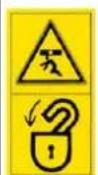
| △WARNINGRisk of injuryRisk of being squeezed or hurt at the belts, side-brushes, waste container, cover. | |
| △DANGERDanger of crushingMake sure that no persons are present in the vicinity of the articulated joint or vehicle during operation.When using the vehicle for towing, make sure that no persons are located during operation between vehicle and trailer. | |
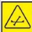
| △WARNINGRisk of cutting, risk of crushingKeep your hands away from this area. | |
| ATTENTIONDamage from incorrect transportDuring the transport, place always the transport lock on the articulated joint. | |
| △WARNINGHealth risk due to poisonous exhaust gasesDo not inhale exhaust gases. | |
| △DANGERRisk of injury due to unauthorised usageRemove the ignition key to protect against unauthorised use and prior to cleaning and maintenance work. |
 | ATTENTIONSafety for cleaning and maintenancePrior to cleaning and maintenance work, park the vehicle on a level and firm subsurface. |
 | △DANGERDanger of injury due to use of unspecified locations for seatingSit exclusively on the driver's seat. |
 | △DANGERRisk of impact, risk of crushingWhen transporting or working under suspended loads, use suitable means for supporting. |
 | Main switch (battery isolation switch) |
 | Lubrication point |
 | Lubricating strip |
 | Lashing point |
 | Quality of the brake fluid and position where brake fluid can be filled.Position of container for brake fluid |
 | Locating point for a jack or a support |
 | Position of main fuse |
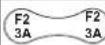 | Position of fuse F2 |
 | Emergency exit |
 | Read operating instructions |
4.10 Position of warning symbols
Note
Immediately replace illegible or lost warning symbols.
4.11 Safety devices
Safety devices protect the user and may not taken out of operation or functionally circumvented.
Adhere to the safety instructions in the chapters!
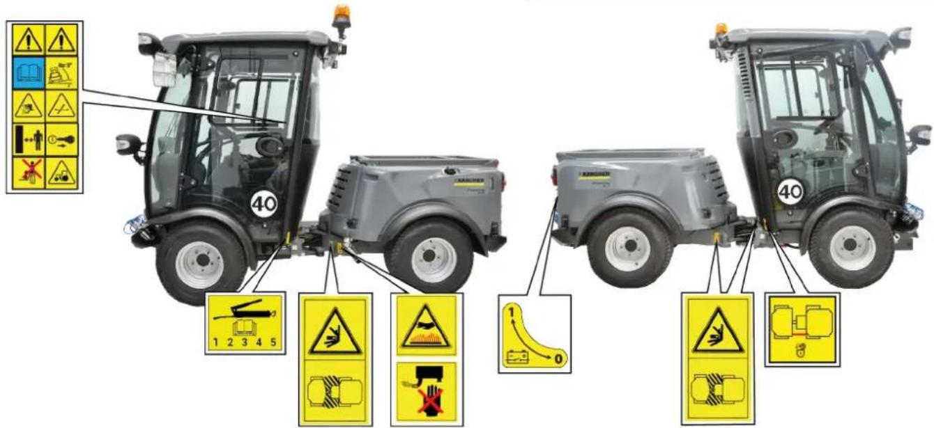
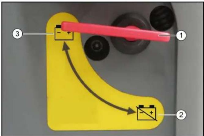
4.11.1 Main switch
①Main switch
②Battery disconnected
③Battery connected
The main switch interrupts the electrical supply line to the starter motor.
If the main switch is pressed when the engine is running (battery disconnected), the engine will stop.
Always disconnect the battery when the vehicle is parked.
4.11.2MIC 70 start inhibit
Requirements for starting the engine:
- Put the main switch into the "battery connected" position.
- Wait until the booting up of the display has been completed.
4.11.3MIC 70 seat contact switch
When the driver's seat is vacant:
- The vehicle will go automatically to neutral position.
Note
Then put the travel direction switch on the joystick to central position
- Is the working hydraulics PTO automatically switched off, or will it get switched off?
4.11.4 Parking brake automatic

The warning light in the multifunction display lights up when the parking brake is active.
1 If the engine has stopped or if the travel direction switch is at NEUTRAL when the engine is running, then the parking brake is activated automatically.
2 If the travel direction switch is pressed when the engine is running (FORWARDS or REVERSE), then the parking brake will be released.
4.11.5Driver cabin
The operator is protected from lightning strikes when sitting in the driver cabin.
The driver cabin has a roll-over protection structure (ROPS), which prevents rolling over after tipping over.
The driver cabin does not have a structure providing protection from falling objects (FOPS).
The driver cabin does not have a structure providing protection from falling objects (OPS).
Always use the safety belt.
5 Batteries / chargers
ATTENTION
Only use the batteries and chargers recommended by the manufacturer
Only replace batteries with batteries of the same type. Before disposing of the vehicle, remove the battery and dispose of it in accordance with national or local regulations.
5.1 Warning symbols
Observe the following warnings when handling the batteries:
 | Observe notes in the instructions for the battery, on the battery and in these operating instructions. |
 | Wear eye protection. |
 | Keep acids and batteries away from children. |
 | Risk of explosion |
 | Fire, sparks, open flames and smoking are prohibited. |
 | Risk of acid burns |
 | First aid. |
 | Warning |
 | Disposal |
 | Do not throw batteries in the bin. |
5.2 Safety instructions
△DANGER
Risk of fire and explosion
Do not place tools or other objects on the battery.
Naked flames and smoking must be strictly avoided.
Ensure the room is well ventilated when charging batteries.
Only use batteries and chargers approved by Kärcher (original spare parts).
⚠ WARNING
Environmental risk due to improper disposal of batteries
Ensure that defect or used batteries are disposed of safely (contact a waste management company or Kärcher Service).
5.3 Procedures in the event of unintentional release of battery acid
When used normally, and when observing the instructions, lead-acid batteries do not pose any risk.
However, keep in mind that lead-acid batteries contain sulphuric acid which can cause serious chemical burns and corrosion.
-
If there is spillage or, if the battery is leaking, acid is escaping, lay down a binding agent such as sand. Do not let it reach the sewer system, soil or a body of water.
-
Neutralise the acid with lime/baking soda and dispose of it according to local regulations.
-
Contact a waste management company to dispose of faulty batteries.
- Rinse out your eyes or rinse off your skin with copious amounts of fresh water if acid splashes into your eyes or onto your skin.
- Then consult a doctor immediately.
- Wash any contaminated clothing with water.
- Change clothes.
6 Overview of the appliance
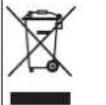
6.1 Front view
①Front light with flasher
②Windscreen wiper
③Working light
④Upper front light with flasher *
⑤Flashing beacon, tiltable
⑥Rear-view mirror, foldable
⑦Driver cabin
⑧Driver's door, lockable
⑨Tipping mechanism *
⑩Fuel cap
⑪Side cladding lock
⑫Factory plate
⑬Mounting frames for attachments
⑭Front power lift
⑮ Hydraulic connections
⑯ Wiping water container
* optional
6.1.1 Front power lift
3-point or 4-point mounts (option) can be fitted to the front power lift. The attachments can be fastened to these mounts.
Certain attachments can be directly attached to the front power lift.
For fitting the attachments, see chapter 9.3 Front mounting options.
6.1.2 Front mounting frames
Certain attachments can be attached directly to the mounting frame for attachments.
For fitting the attachments, see chapter 9.3 Front mounting options.
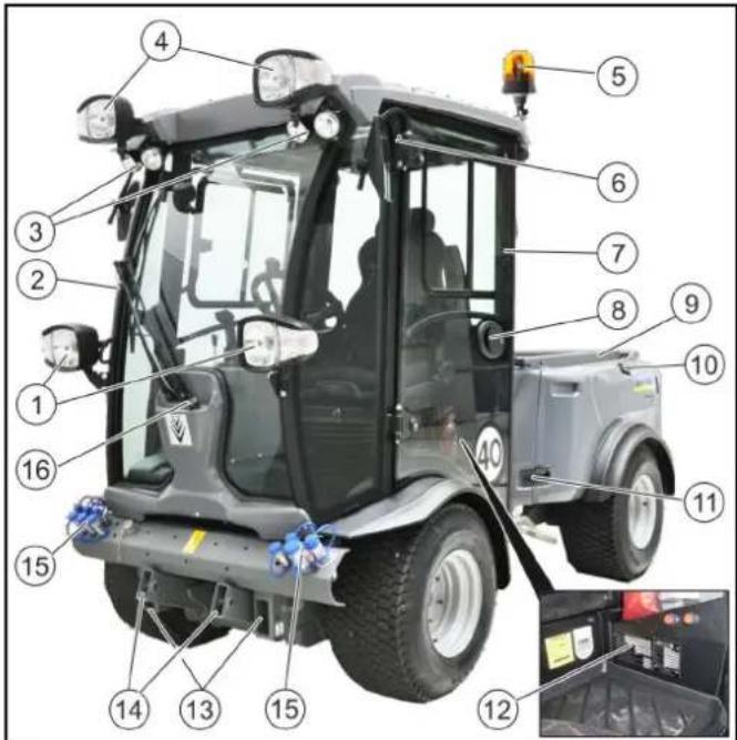
6.2 View of the side
①Transport lock articulated joint
②Rear wheel
③Side cover lock
④Hydraulic oil level display
⑤Cabin doors, lockable
⑥Driver cabin dust filter
⑦Front wheel
⑧Diesel particulate filter (only MIC 70)
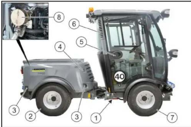
6.3 View of the rear
①Taillamp with flasher
②Main switch
③Hydraulic connections
④Mounting frames for attachments
⑤Tow bar
⑥Trailer power socket
⑦Hydraulic connections
⑧Recesses, prepared for optional connections
⑨Electrical PTO 6-pole connection *
⑩Recess, prepared for optional reversing camera
⑪Work light
⑫Licence plate bracket
⑬Tipping mechanism *
* optional
6.3.1 Rear mounting frames
Counterweights and certain attachments can be attached directly to the mounting frame for attachments.
For fitting the attachments, see chapter 9.5 Rear mounting options.
6.4 Hydraulic and electrical connections
Definition of the term, hydraulic PTO
Power Take Off = hydraulic force output
Definition of the term, AUX
Auxiliary = auxiliary hydraulic valve
Definition of the term, electrical PTO
Power Take Off = electrical force output
6.4.1 Connections for MIC 70 front attachment
Note
Fit a dust cap to an unused connection to provide protection.
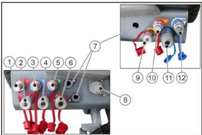
①AUX 1+ (A - red)
②AUX 1- (B - red)
③AUX 2+ (A - blue)
④AUX 2- (B - blue)
⑤AUX 3+ (A - green)
⑥AUX 3- (B - green)
⑦Recesses (prepared for optional connections)
⑧Electrical PTO
⑨Leakage oil
⑩ Hydraulic PTO flow (50 litres/min)
⑪ Hydraulic PTO return flow
⑫ Hydraulic PTO flow (100 litres/min)
Note
The hydraulic connections AUX are controlled using the joystick.
Note
The hydraulic PTO is activated using the hydraulic PTO selector switch in the operating console.
For a description of the selector switch, see chapter 6.10.2
Centre operating console for MIC 70.
6.4.2 Connections for MIC 70 rear attachment
Note
Fit a dust cap to an unused connection to provide protection.
①Electrical PTO
②Recess (prepared for optional connection)
③AUX + (A - purple)
④AUX - (B - purple)
⑤Recess (prepared for optional connection)
⑥Leakage oil
⑦ Hydraulic PTO flow (100 litres/min)
⑧Hydraulic PTO flow (50 litres/min)
⑨Hydraulic PTO return flow
Note
The hydraulic connections AUX are controlled using the control lever.
Note
The hydraulic PTO is activated using the hydraulic PTO selector switch in the operating console.
For a description of the selector switch, see chapter 6.10.2
Centre operating console for MIC 70.
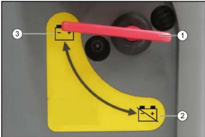
6.5 Main switch
①Main switch
②Battery disconnected
③Battery connected
The main switch interrupts the electrical supply line to the starter motor.
If the main switch is pressed when the engine is running (battery disconnected), the engine will stop.
Always disconnect the battery when the vehicle is parked.
6.6 Driver cabin
The operator is protected from lightning strikes when sitting in the driver cabin.
The driver cabin has a roll-over protection structure (ROPS), which prevents rolling over after tipping over.
The driver cabin does not have a structure providing protection from falling objects (FOPS).
The driver cabin does not have a structure providing protection from falling objects (OPS).
Always use the safety belt.
6.6.1 Doors
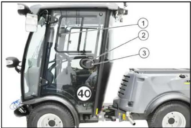
①Sliding windows
②Door handle
③Ignition key
The driver's door is located at the left side in the travel direction, the emergency exit is located at the right side.
The handle on the B-pillar can be used as an aid for entering and exiting the cab.
Lock both doors with the ignition key after parking the vehicle.
6.6.2 Emergency exit
The emergency exit is located at the right side in the travel direction.
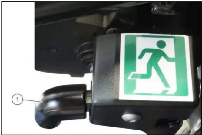
①Door handle
Open the emergency exit by pulling the door handle.
6.6.3 Emergency hammer
The emergency hammer is located at the top right, behind the emergency exit.
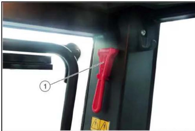
①Emergency hammer
In case of emergency, smash the windows using the emergency hammer.
Note
Both side windows and the rear window can be smashed in.
6.6.4 Interior lights
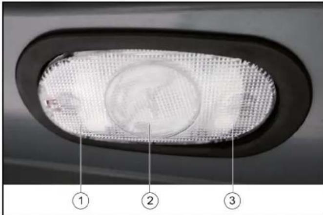
①Pressed down left: Lights switched on
② Centre position: The light is switched on when a door is opened
③Pressed down right: Lights switched off
6.6.5 Switch panel
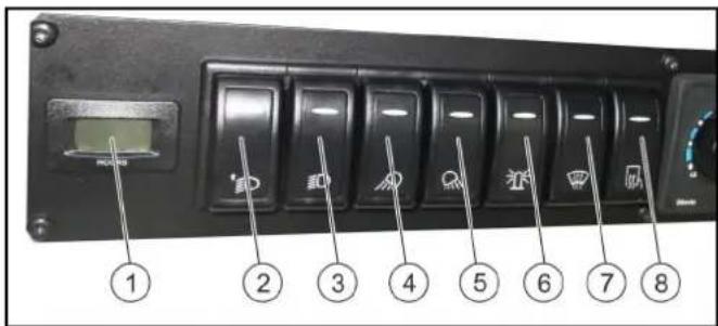
①PTO operating hours counter
②Switch for lighting top / bottom Position 0: Dipped headlights bottom on Position 1: Dipped headlights top on
③Lighting switch Position 0: Dipped headlights off Position 1: Parking light on Position 2: Dipped headlights on
④Switch for front work lights
⑤Switch for rear work lights
⑥Switch for beacon light
⑦Switch for heatable windscreen (option)
⑧Switch for heatable outside mirror (option)
Note
The displays in the switch light up if the lights are switched on.
6.6.6 Radio
The optionally available radio is locate in the ceiling console.
See the manufacturer's operating instructions for operating the radio.
6.6.7 Heating, ventilation, air-conditioner
Note
Adjust the airflow to be free of draughts.
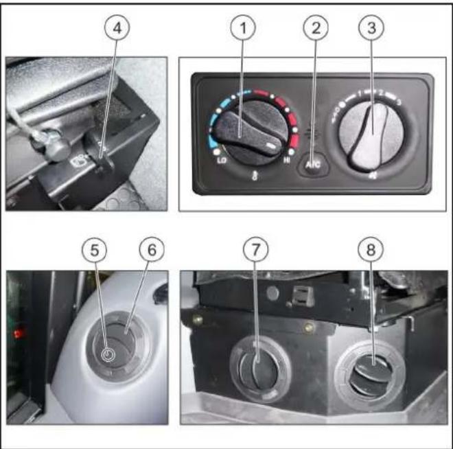
① Heating temperature control
②Switch for air-conditioner
Note
The switch is available in all versions; the air-conditioner function is optional
③Air fan controller
④ Lever for air recirculation
Note
Air recirculation: Lever forwards
Only use this function for a limited period, since air is not exchanged from the outside with this setting.
⑤Press to open the air nozzle.
⑥Air nozzle on front dashboard
⑦Air nozzle on front seat console
⑧Air nozzle on side seat console
6.6.8 Cover console indicator lamps
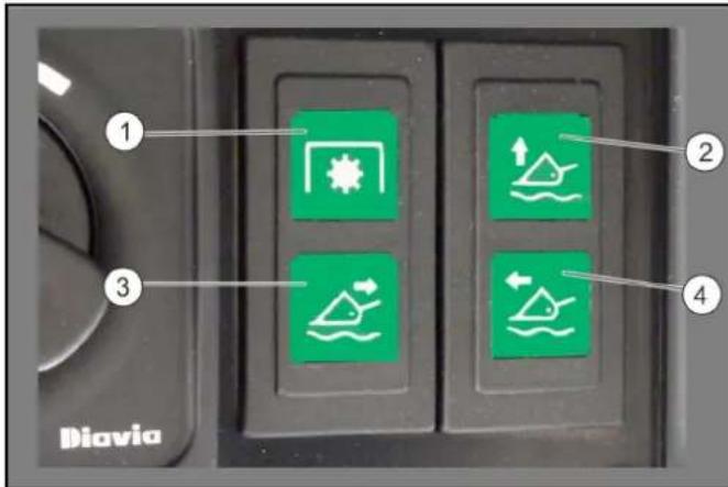
①Hydraulic PTO active
②Floating position for front power lift active
③Floating position for AUX red active
④Floating position for AUX blue active
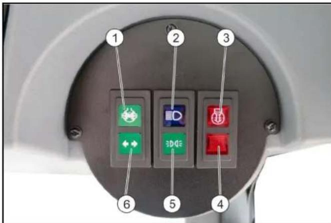
① Differential lock
②High beam
③Contamination of engine air filter
④Not used
⑤Dipped headlights (dipped beam)
⑥Flasher
6.7 MIC 70 multifunction display / display
The default display language is English, but the language can be changed via the Settings menu, see chapter 6.7.3 Setting the language on MIC 70.
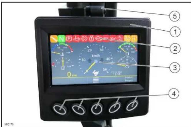
①Multifunction display, adjustable in height
②Display
③Warning lights and indicator lamps
Note
Whilst the system is starting up, all the warning lights and indicator lamps briefly light up. This can be used for monitoring purposes, in order to check that the lights are working correctly.
④Function buttons
⑤ Lever for height adjustment
The function buttons are used for navigating, changing the settings or for directly selecting a menu. This is visually seen in the navigation display in the display.
In order to adjust the multifunction display in height, open the lever and set to the required position.
6.7.1 Warning lights and indicator lamps
△WARNING
Risk of damage to vehicle
If a red warning light lights up, then you must take immediate measures to rectify the fault. Search for the next opportunity for safely stopping out of the moving traffic.
ATTENTION
If a yellow warning light lights up, then you must take measures to rectify the fault as soon as possible.
Note
Green and blue indicator lamps indicate the current activities of the vehicle.
- The significance of the warning lights that light up in the event of a malfunction is described in chapter 14 Troubleshooting guide.
6.7.2 MIC 70 display settings
ATTENTION
Do not start the engine during the adjustment process. The following settings can be selected or changed.
| Display brightness | |
| bar | |
| AutoInhibit | |
| format:YYYY-MM-DDDD.MM.YYYY | |
| Time and time format24 h12 h | |
| LanguageNot all languages are available;select the relevant languageavailable |
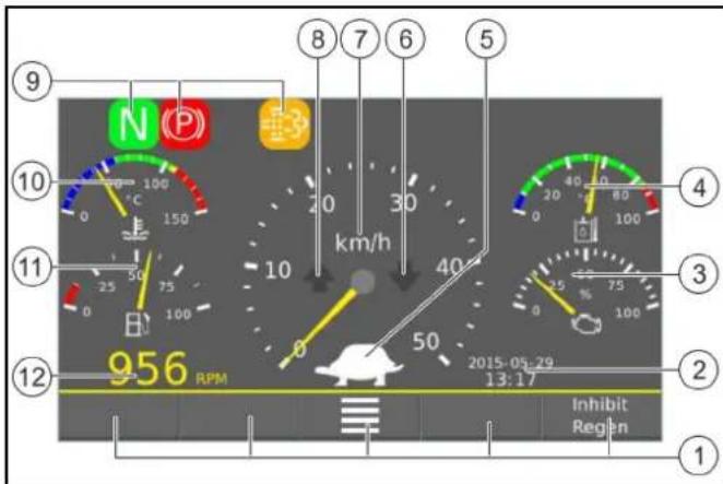
①Navigation display
②Display of time and date
③Drive
④Hydraulic oil temperature
⑤Display for transport mode or working mode
⑥Indication for travel direction preselection "reverse"
⑦Travel speed display
⑧Indication for travel direction preselection "forwards"
⑨Warning lights / indicator lights
⑩Engine cooling water temperature
⑪Filling level of fuel tank
⑫Engine speed
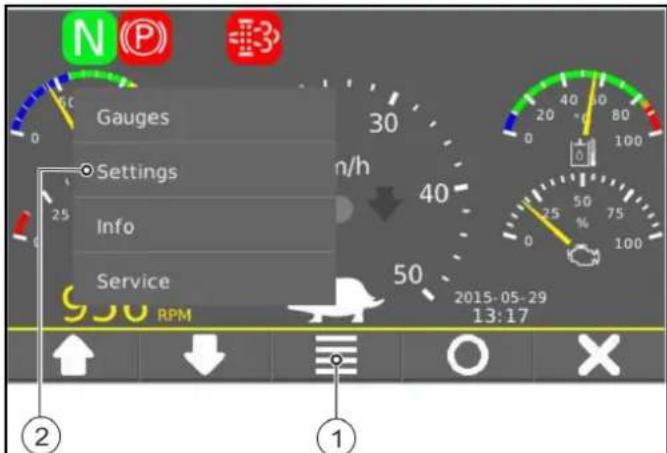
ATTENTION
The menu item
①Menu
②Selection of
- Switch on the ignition.
- Press the function button for the menu and navigate to
. - Use the function buttons on the navigation display to navigate within the menu.
- Select the settings.
- Press
: Confirm selected setting. - Press
: Return / cancel. - Navigate to
Setting the time
To save the time and date, the system has to be restarted.

- Press
, the system will be restarted. Date and time are saved. - Press
to cancel.
6.7.3 Setting the language on MIC 70
- Switch on the ignition.
- Press the function button for the menu and navigate to
. - Confirm using the circle symbol
. - Use the
function button to navigate to the right-hand level. - Use the
function button to navigate to the language. - Select the required language.
- Switch off the ignition - the selected language is saved.
6.7.4 Settings for working mode
Note
When switching over from TRANSPORT MODE to WORKING MODE (see chapter8.1 Operating programs), the engine speed and speed settings are changed.
Note
If the potentiometer for engine speed (see chapter6.10 Operating consoles) is not in the end position (0), then a display will appear.
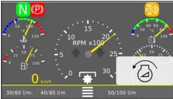

If this display appears, turn the potentiometer for engine speed anticlockwise to the end position (0).
Working mode
In WORKING MODE, it is possible to choose between 3 options. These options influence the engine speed and hydraulic power.
- 30/60 l/min
The engine speed is limited to a max. 1600 rpm, and the hydraulic power to 30 l/min, if the hydraulic PTO selector switch is at 50 l/min.
The engine speed is limited to a max. 1600 rpm, and the hydraulic power to 60 l/min, if the hydraulic PTO selector switch is at 100 l/min.
- 40/80 l/min
The engine speed is limited to a max. 2200 rpm, and the hydraulic power to 40 l/min, if the hydraulic PTO selector switch is at 50 l/min.
The engine speed is limited to a max. 2200 rpm, and the hydraulic power to 80 l/min, if the hydraulic PTO selector switch is at 100 l/min.
- 50/100 l/min
Maximum hydraulic power and maximum engine speed.
Note
The selected setting is also kept when switching over between WORKING MODE AND CREEPING MODE.
When switching over to TRANSPORT MODE, the setting is reset and the engine goes to idle speed.
After an option has been selected, the relevant display will appear on the display (bottom right).
Changing to the option selection increases or reduces the current speed, unless the engine is in idle mode.

Press the function button to return to the option selection.
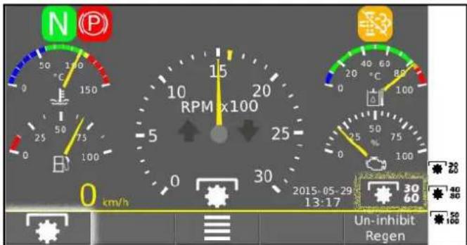
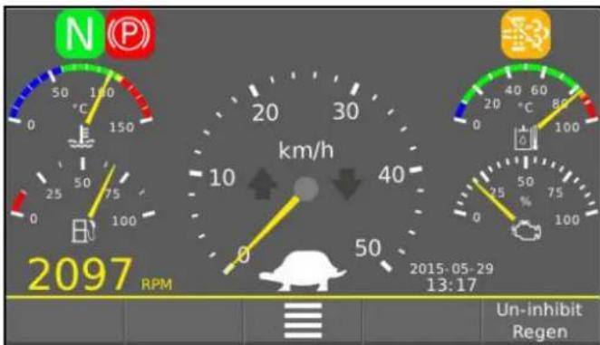
Illustration: Selected maximum speed = 1600 rpm and current speed 1500 rpm (engine is running)
The selected speed is displayed in the from of a small, yellow arrow. The idle speed is always 950 rpm (minimum speed).
The yellow needle indicates the current speed.
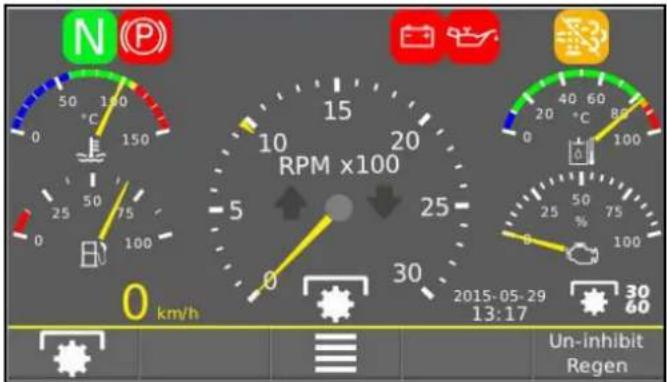
Illustration: Idle speed 950 rpm and current speed = 0 (engine off)
6.8 Foot room with pedals
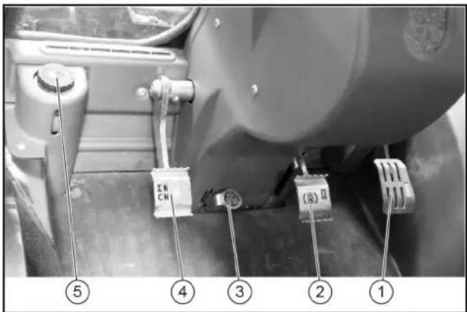
①Accelerator pedal
②Brake pedal
③Steering wheel inclination adjustment pedal
④Inching pedal
⑤Brake fluid container
6.8.1 Accelerator
ATTENTION
Other than in a normal motorcar, releasing the accelerator pedal abruptly reduces the speed.
The braking force applied when you release the accelerator pedal is weaker in higher gears and stronger in lower gears.
The braking force applied when you release the accelerator pedal in transport mode is significantly weaker than in working mode.
Pressing the accelerator pedal increases the engine speed.
The accelerator pedal is sprung. Releasing the accelerator pedal reduces the engine speed.
The hydrostatic drive brakes or stops the vehicle when the accelerator pedal is released.
6.8.2 Parking brake
Parking brake for securing the parked vehicle.
Note
If the "Parking brake active" warning light in the display lights up then the parking brake is engaged.
6.8.3 MIC 70 brake pedal
The brake pedal activates the front and rear wheel braking system.
6.8.4 Inching pedal
The inching pedal regulates the speed in WORKING MODE and CREEPING MODE.
To decrease the travel speed, press the inching pedal.
Note
The inching pedal can also be used as a brake pedal; to do so, step on the inching pedal to the floor.
6.9 Multi switch on the steering wheel
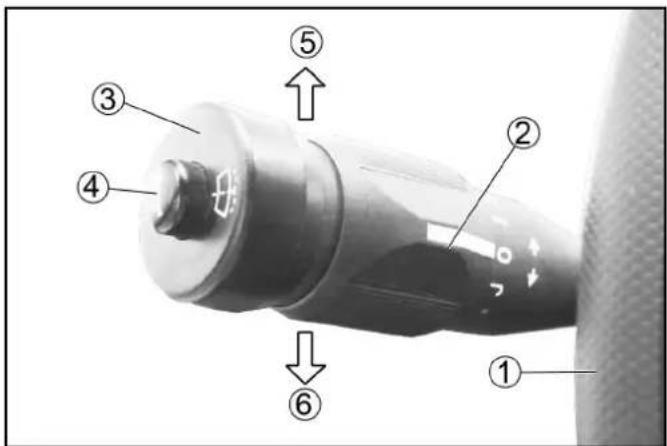
①Steering wheel
②Windscreen wiper
Position J: Intermittent operation
Position 0: Off
Position I: Normal
Position II: Fast
③Windscreen washer fluid
Press to actuate
④Horn
Press to actuate
⑤Indicate right
⑥Indicate left
6.10 Operating consoles
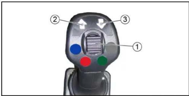
6.10.1 Front operating console for MIC 70
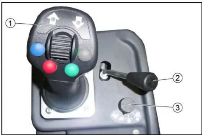
①Joystick
All the front attachments are controlled with the joystick.
②Control lever
The control lever is used to control the rear attachments.
③Preselection of operating programs
Joystick
All the front attachments are controlled with the joystick.
The joystick can be moved in X direction and in Y direction.
- Moving in X direction (left and right) controls the connected up attachments.
Moving in Y direction (front and back) lifts or lowers the front device carrier to which the attachment is fastened.
- To activate / deactivate the floating position (AUX red or blue), press the relevant button on the joystick.
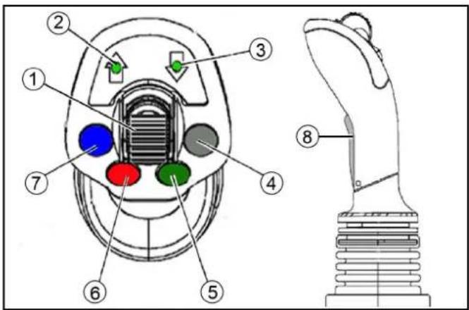
①Travel direction selector switch
② Indication for travel direction preselection "forwards"
③ Indication for travel direction preselection "reverse"
④Not used
⑤Double-acting hydraulic connection AUX green
⑥Double-acting hydraulic connection Floating position for AUX red
⑦Double-acting hydraulic connection Floating position for AUX blue
⑧AUX blue
Control lever
Depending on the activation of the switch for "AUX rear/attachment frame with tipping mechanism", the control lever is used for:
• Controlling the rear attachments
- Lifting and lowering the attachment frame with tipping mechanism
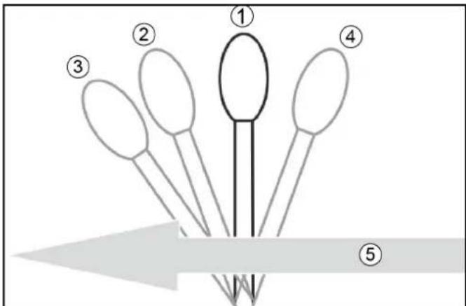
①Neutral position
②Lowering and pressing down, the lever does not engage
③Lowered in floating position, the lever engages
Note
Attachment tracks the floor (e.g. brush)
④Lifting, the lever does not engage
⑤Forwards direction of travel
6.10.2 Centre operating console for MIC 70
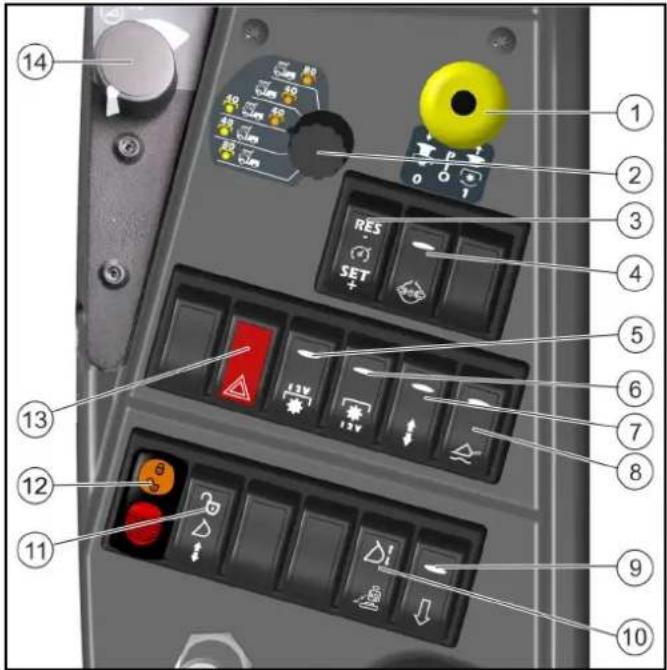
①PTO on/off
Position 1: Switch on the PTO
Press the black knob and pull the button
PTO on/off
Position 0: Switch off the PTO
Press the button downwards.
②Selector switch for hydraulic PTO
③Tempomat
④Differential lock
⑤Electrical PTO, front
⑥Electrical PTO, rear
⑦Switchover for double-acting control hydraulics AUX "rear/attachment frame with tipping function"
⑧Main switch, floating position
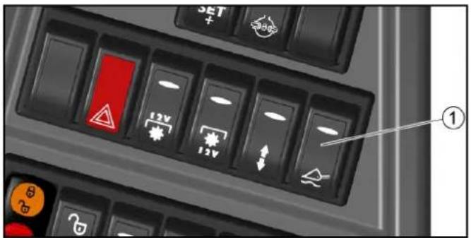
⑨Dump valve (quick-lowering for AUX rear)
⑩Attachment release switch (optional)
Note
This switch is responsible both for vibration dampening and for attachment release (both options at the same time does not work)
⑪ Locking enabling for shovel or fork in the optional front loader attachment
⑫Switch for bypassing floating position (PTO usable without floating position)
ATTENTION
Only use with attachments that need this function!
⑬Hazard warning switch
⑭Potentiometer - engine speed
Selector switch for hydraulic PTO
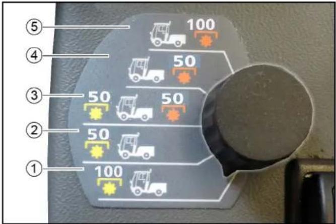
①Hydraulic PTO (100 l/min, front) activated
②Hydraulic PTO (50 l/min, front) activated
③Hydraulic PTO (50 l/min, front) and (50 l/min, rear) activated
④Hydraulic PTO (50 l/min, rear) activated
⑤Hydraulic PTO (100 l/min, rear) activated
The selector switch is used to activate the relevant connection for the front and rear hydraulic PTO.
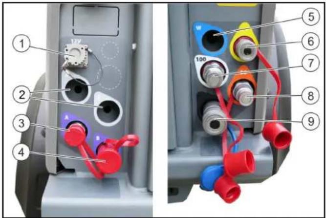
6.10.3Rear operating console for MIC 70
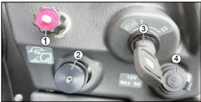
①Rotary knob for front power lift lowering speed
②Rotary knob for attachment release
③Ignition lock
④Additional socket-outlet, 12 V
Ignition lock
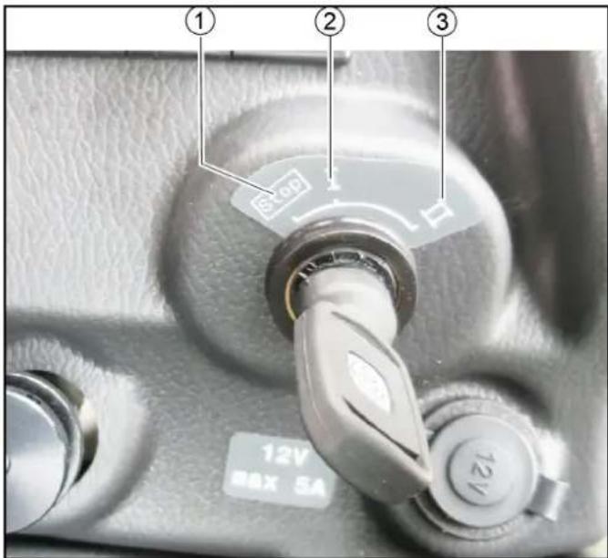
①Engine off
②Ignition on
③Start the engine
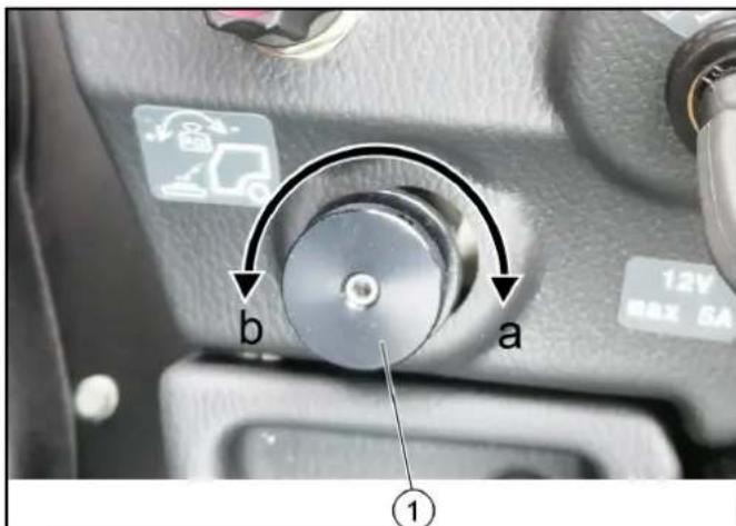
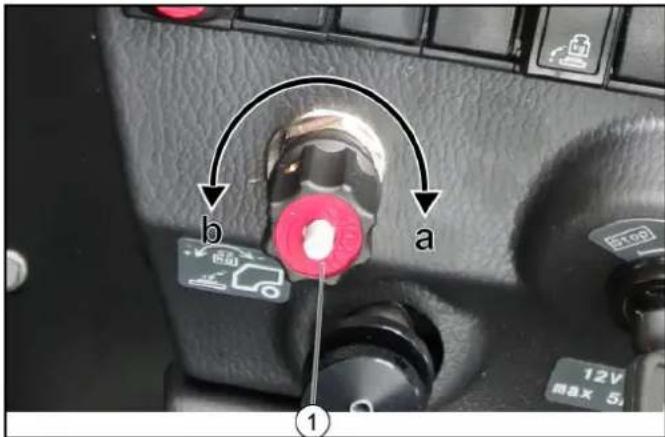
6.10.4 Setting the lowering speed of the front power lift
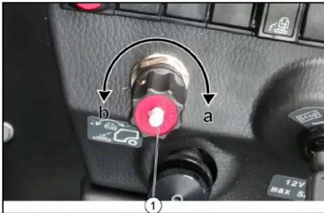
①Rotary knob, lowering speed
- Switch off the PTO (working hydraulics).
- Select the front power lift lowering speed using the rotary knob.
a Turning clockwise: The lowering speed is reduced. The front power lift is blocked at the limit stop
Note: This function is needed for transport journeys on public roads in order to disable the front power lift and thus the lowering of the attachments.
b Turning anticlockwise: The lowering speed is increased
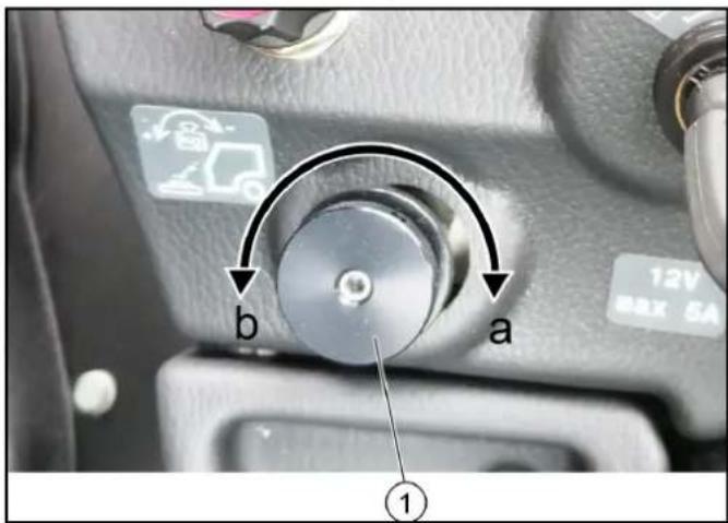
6.10.5 Attachment release and vibration dampening (optional)
The attachment release is used in order to move the load from one attachment fitted on the front power lift towards the vehicle's front axle.
For example: If a mower deck is being used, the forces in the ground are reduced by the mower deck in order to reduce damage to the ground due to the wheels spinning; especially when driving uphill.
Note
If the attachment is raised whilst the attachment release system is switched on, it will act like a load stabilisation system when driving.
Vibration dampening (optional) ensures a more comfortable and stable drive during transport journeys with a raised attachment on the front power lift.
①Rotary knob for attachment release
-
Switch on the attachment release system using the switch (on the centre console).
-
Change the shift in the centre of gravity using the attachment release rotary knob. a Turning clockwise: More weight on the front axle b Turning anticlockwise: Less weight on the front axle
7 Initial startup
△CAUTION
Read the operating instructions for attachments!
When using attachments or pulled devices and trailers prior to initial startup, read the corresponding operating instructions and follow them.
Pay attention to permissible loads, see chapter .
7.1 Switching on the main switch
①Main switch
②Battery disconnected
③Battery connected
-
To start the engine, put the main switch into the "battery connected" position.
-
When the vehicle is parked, put the main switch into the "battery disconnected" position.
7.2 Safety check
△DANGER
Risk of accidents and injuries!
Do not start up the vehicle when one item of the safety check is not fulfilled; make sure the item is repaired.
Check the operational and traffic safety of the vehicle before driving.
-
Check the cleanliness of the hydraulic couplings
-
Check the hydraulic lines for leaks
-
Check the hydraulic oil level
-
Check the engine oil level
-
Check the coolant level
-
Check the coolant for sufficient antifreeze if a danger of frost exists
Antifreeze in the appropriate concentration generally belongs in the cooling circuit (not in the expansion reservoir).
-
Check the electrical cables for damage
-
Check that all nuts and bolts are securely seated
-
Check the vehicle, engine and radiator grille for damage
-
Check the fluid level in the wiping water container Check the detergent and frost protection, if applicable
-
Check the tyres for damage, filling pressure and wear and tear
In the vehicle
- Check all pedals for ease of movement
13.Are the working hydraulics (PTO) switched off?
- With the ignition switched on: Do the charge indicator and oil pressure warning lights light up?
Start the engine and check the following:
15.Do the charge indicator and oil pressure warning lights go out?
-
Are the temperature indicator and fuel level indicator functioning?
-
Are the lighting system, travel direction indicator and flasher system functioning correctly?
7.3 Setting the driver's seat (standard seat)
△DANGER
Danger of accident
Only adjust the driver's seat when the device is standing.
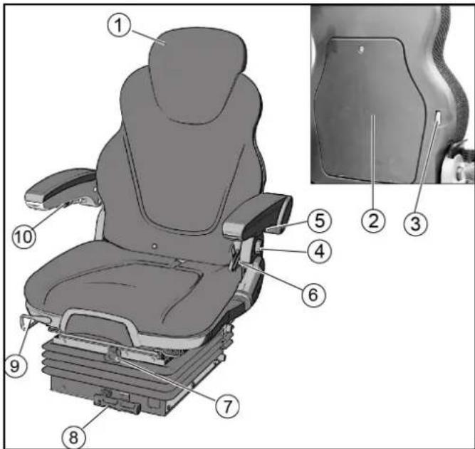
①Headrest
②Document storage
③Lumbar support adjustment
④Backrest inclination adjustment
⑤Left arm rest height adjustment
Can be folded upwards for entry and exit to/from cab.
⑥Seat belt
⑦Height adjustment
⑧Shock absorber / driver's weight adjuster
⑨Horizontal adjustment
⑩Right arm rest height adjustment
- Adjust the driver's seat so that the pedals and steering wheel are easily reached.
- Bring the left arm rest to the desired position.
- Bring the right arm rest to the desired position.
- Adjust the driver's seat to suit the weight of the driver so that vibration from road irregularities are minimised. a The driver's seat complies with class A, weight class I b Check the lock prior to travel commencement.
7.4 Setting the driver's seat (comfort seat, optional)
△DANGER
Danger of accident
Only adjust the driver's seat when the device is standing.
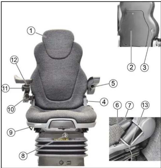
①Headrest
②Document storage
③Lumbar support adjustment
④Backrest inclination adjustment
⑤ Left arm rest height adjustment
Can be folded upwards for entry and exit to/from cab.
⑥Seat heater switch
⑦Seat belt
⑧Height adjustment / driver's weight adjuster
⑨Horizontal adjustment
⑩Right arm rest height adjustment
⑪ Right arm rest side adjustment
⑫ Right arm rest longitudinal adjustment
⑬Horizontal shock absorber
- Adjust the driver's seat so that the pedals and steering wheel are easily reached.
- Bring the left arm rest to the desired position.
- Bring the right arm rest to the desired position.
- Adjust the driver's seat to suit the weight of the driver so that vibration from road irregularities are minimised. a Check the lock prior to travel commencement.
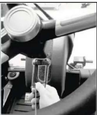
7.5 Setting the steering wheel position
△DANGER
Danger of accident
Only adjust the position of the steering wheel when the device is standing.
natural_image
Close-up of a car's side panel with attached lock and safety tags (no visible text or symbols)1
natural_image
Close-up of a hand using a tool to adjust or install a component, no visible text or symbols②
①Steering wheel inclination adjustment pedal
②Steering wheel height adjustment locking lever
-
Release the height adjustment locking lever and set the steering wheel to the desired height.
-
Release the height adjustment locking lever and set the steering wheel to the desired height.
-
Lock the locking lever.
-
Press and hold the inclination adjustment pedal and set the steering wheel to the desired inclination.
-
Release the pedal.
-
Check the locks prior to travel commencement.
-
Release the height adjustment locking lever and set the steering wheel to the desired height.
- Lock the locking lever.
- Press and hold the inclination adjustment pedal and set the steering wheel to the desired inclination.
- Release the pedal.
- Check the locks prior to travel commencement.
7.6 Refuelling
△DANGER
Risk of explosion
Do not refuel in confined spaces.
Do not smoke and avoid open flames.
Ensure that no fuel gets on hot surfaces.
- Switch off the ignition.
- Open the tank cap.
- Fill with fuel.
Only the fuel specified in the operating instructions may be used.
- Wipe of any spilt fuel and close the tank cap.
8 Operation
DANGER
Danger of crushing
Make sure that no persons are present in the vicinity of the articulated joint or vehicle during operation.
When using the vehicle for towing, make sure that no persons are located during operation between vehicle and trailer.
△CAUTION
Risk of burns
Only use the vehicle if all panels are attached.
ATTENTION
Risk of damage due to overheated hydraulic oil or overheated motor!
In case of excessive hydraulic oil temperature or an excessive coolant temperature, set the motor speed to idle mode (do not switch off the motor).
Perform the measures in the "Malfunctions" section
ATTENTION
Risk of damage due to missing lubrication
If the warning light for the oil pressure lights up during operation, immediately move the vehicle out of the danger zone, switch off the motor immediately and rectify the fault.
△CAUTION
Reduced stability due to attachments
Adjust the driving style.
8.1 Operating programs
ATTENTION
Risk of damage
Only choose the operating program selection when the vehicle has been shut down.
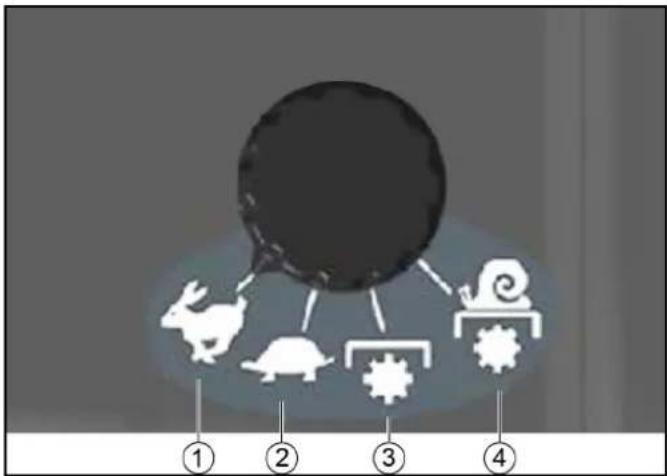
flowchart
graph TD
    A["Large Circle"] --> B["Rabbit"]
    A --> C["Rabbit"]
    A --> D["Tweater Gear"]
    A --> E["Sneal Gear"]
    B --> F["①"]
    C --> G["②"]
    D --> H["③"]
    E --> I["④"]
①TRANSPORT MODE FAST
②TRANSPORT MODE SLOW
③WORKING MODE
④CREEPING MODE
- Stop the vehicle.
- Set the engine speed to low speed.
- Travel direction selector switch to the NEUTRAL position (switch at central position).
8.1.1
The travel speed is regulated using the accelerator. Max. 40 km/h
Note
In
8.1.2
The travel speed is regulated using the accelerator. Maximum speed approx. 20 km/h
Note
In
8.1.3
Max. 20 km/h
Note
More information on the
8.1.4
Forwards: Max. 5 km/h
Reverse: Max. 10 km/h
Note
More information on the
8.2 Foot room with pedals

①Accelerator pedal
②Brake pedal
③Steering wheel inclination adjustment pedal
④Inching pedal
⑤Brake fluid container
8.2.1 Accelerator
ATTENTION
Other than in a normal motorcar, releasing the accelerator pedal abruptly reduces the speed.
The braking force applied when you release the accelerator pedal is weaker in higher gears and stronger in lower gears.
The braking force applied when you release the accelerator pedal in transport mode is significantly weaker than in working mode.
Pressing the accelerator pedal increases the engine speed.
The accelerator pedal is sprung. Releasing the accelerator pedal reduces the engine speed.
The hydrostatic drive brakes or stops the vehicle when the accelerator pedal is released.
8.2.2 Parking brake automatic

The warning light in the multifunction display lights up when the parking brake is active.
1 If the engine has stopped or if the travel direction switch is at NEUTRAL when the engine is running, then the parking brake is activated automatically.
2 If the travel direction switch is pressed when the engine is running (FORWARDS or REVERSE), then the parking brake will be released.
8.2.3 MIC 70 brake pedal
The brake pedal activates the front and rear wheel braking system.
8.2.4 Inching pedal
The inching pedal regulates the speed in WORKING MODE and CREEPING MODE.
To decrease the travel speed, press the inching pedal.
Note
The inching pedal can also be used as a brake pedal; to do so, step on the inching pedal to the floor.
8.3 Drive mode
8.3.1 Starting the engine, MIC 70
The main switch must be switched on.
- Sit in the driver's seat and put on your seat belt.
- Insert the ignition key in the ignition lock.
- Travel direction selector switch on the joystick to central position
. - Switch on the ignition (position I).
Charge indicator and engine oil pressure warning lights have to light up.
- In the event of low outside temperatures and a cold engine: Delay starting until the text display
goes out. - Start the engine (position II) - max. 10 seconds.
The charge indicator and engine oil pressure warning lights have to go out; if not, switch off the engine and remedy the fault.
- In the event of ambient temperatures below 0^ C: Before commencing with work, allow the engine to warm up at a low engine speed until the yellow warning light
goes out. - If the engine does not start, then repeat the starting procedure.
8.3.2 Tempomat
The Tempomat only works in WORKING MODE and CREEPING MODE.
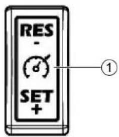
①Tempomat switch
Activating Tempomat
- Select the desired working speed using the accelerator.
- If the vehicle moves at the required speed, press SET on the Tempomat switch. Tempomat is activated. a Increasing the speed afterwards: Press SET + b Decreasing the speed afterwards: Press RES - c The speed can be reduced in the short term using the inching pedal. If the inching pedal is released, the vehicle will move at the set engine speed again.
Deactivating Tempomat
- The brake pedal has to be pressed or the inching pedal stepped on in order to deactivate Tempomat. After deactivating Tempomat, pressing RES (during the run) will reactivate the previously saved speed.
8.3.3 Selecting the travel direction
The travel direction selector switch can be found on the joystick.
Note
If the driver leaves the driver's seat whilst the travel direction selector switch is in "forwards" or "reverse", then the engine will switch off.
①Travel direction selector switch
②Indication for travel direction preselection forwards
③Indication for travel direction preselection reverse
- FORWARDS: The switch goes forwards; travel direction FORWARDS will be activated and the indicator for travel direction preselection "forwards" lights up.
The parking brake is automatically released in this position.
- REVERSE: The switch goes backwards; travel direction REVERSE will be activated and the indicator for travel direction preselection "reverse" lights up.
The parking brake is automatically released in this position.
- NEUTRAL: Switch setting is in the middle; a display does not light up.
In this position, the parking brake is automatically actuated; the vehicle does not move.
8.3.4 Driving
△CAUTION
Risk of accident
Do not let go of the accelerator pedal abruptly during driving. The vehicle will be braked when the accelerator pedal is released. The vehicle will be decelerated to a lesser extent when the accelerator pedal is released in transport mode rather than in operating mode.
△CAUTION
Risk of damage
Make sure that the vehicle does not become stuck when driving over obstacles.
Drive over obstacles up to 150 mm slowly and carefully at an angle of 45^ .
Obstacles above 150 mm may only be driven over using a suitable ramp.
△CAUTION
Risk of accident
When driving on public roads for transport purposes (and not when cleaning of public roads), switch off the PTO and close the lowering choke for the front power lift.
-
Switch off the PTO.
-
Carefully press the accelerator.
-
Steer the vehicle using the steering wheel.
8.3.5 Stopping
- Release the accelerator pedal.
The vehicle brakes automatically and comes to a standstill.
- For a stronger braking effect or in case of an emergency, actuate the brake pedal.
8.4 Parking the vehicle
ATTENTION
Risk of injury
Lower the attachments before leaving the vehicle.
-
Stop the vehicle.
-
Travel direction selector switch on the joystick to central position
. -
Allow the engine to run in idle mode for 1 to 2 minutes.
-
Switch off the ignition and remove the ignition key.
-
Wait 30 seconds.
-
Turn the main switch to position 0.
8.5 Front power lift
A 4-point mount (option) can be fitted to the front power lift. The corresponding attachments can be attached to this.
Certain attachments can also be directly attached to the front power lift.
ATTENTION
Risk of injury and damage
Ensure that the permissible axle load is not exceeded when fitting attachments to the front power lift.
You are not permitted to operate the front power lift when persons are in the vicinity of the front power lift and fitted attachments.
Ensure that attachments fitted to the front power lift do not touch or damage the vehicle.
8.5.1 Setting the lowering speed of the front power lift
①Rotary knob, lowering speed
-
Switch off the PTO (working hydraulics).
-
Select the front power lift lowering speed using the rotary knob.
a Turning clockwise: The lowering speed is reduced. The front power lift is blocked at the limit stop Note: This function is needed for transport journeys on public roads in order to disable the front power lift and thus the lowering of the attachments.
b Turning anticlockwise: The lowering speed is increased
8.5.2 Attachment release and vibration dampening (optional)
The attachment release is used in order to move the load from one attachment fitted on the front power lift towards the vehicle's front axle.
For example: If a mower deck is being used, the forces in the ground are reduced by the mower deck in order to reduce damage to the ground due to the wheels spinning; especially when driving uphill.
Note
If the attachment is raised whilst the attachment release system is switched on, it will act like a load stabilisation system when driving.
Vibration dampening (optional) ensures a more comfortable and stable drive during transport journeys with a raised attachment on the front power lift.
①Rotary knob for attachment release
- Switch on the attachment release system using the switch (on the centre console).
- Change the shift in the centre of gravity using the attachment release rotary knob.
a Turning clockwise: More weight on the front axle
b Turning anticlockwise: Less weight on the front axle
8.5.3 Operating the front power lift
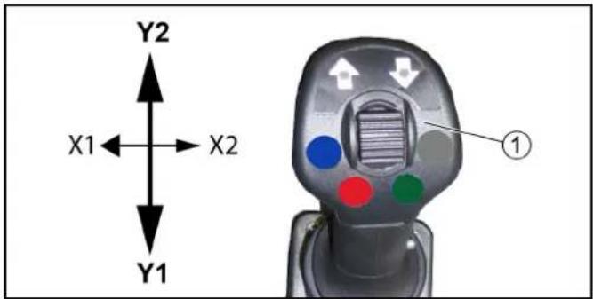
①Joystick
- Pull the joystick backwards (direction Y1) to raise the front power lift.
- Push the joystick forwards (direction Y2) to lower the front power lift.
Floating position
①Main switch, floating position
-
The floating position is switched on and off using the floating position main switch. The floating position must be switched off when driving on public roads for transportation purposes (not when cleaning public roads).
-
Press the joystick in the Y2 direction briefly to switch the floating position function on. The joystick then returns to the NEUTRAL position.
In the floating position, the attachment follows the ground contour.
- Pull the joystick in the Y1 direction to switch the floating position function off.
9 A t t a c h m e
Note
Please read the attachment operating instructions before fitting an attachment.
Attachments are optional and can be fitted to the front power lift (see chapter 8.5 Front power lift) or to the front or rear mounting frames.
△DANGER
Danger due to change to vehicle's centre of gravity and to driving characteristics. When transporting fluids, sloshing motion may occur, which will then rock the vehicle.
In the case of modifications, particularly when converting from winter to summer use and in the case of changes to load conditions, the driver must be prepared for the change in driving characteristics.
⚠ WARNING
Risk of crushing when attaching attachments
Do not reach between the front power lift and the attachment.
△CAUTION
Risk of burns from hot hydraulic couplings
Wear protective gloves when disconnecting the hydraulic couplings.
ATTENTION
Wear suitable protective clothing, safety gloves and gloves when installing and removing attachments. This also applies during usage and application.
Please contact your responsible dealer before fitting attachments that are not specifically intended for this vehicle. Your dealer will check if installation and use of these attachments is permitted on your vehicle. This is important for the safety of the driver and the vehicle and also for any warranty claims.
Attachments that endanger the safety or stability of the vehicle may not be used.
9.1 Coupling attachments to the vehicle
ATTENTION
Risk of damage
Keep hydraulic connections clean.
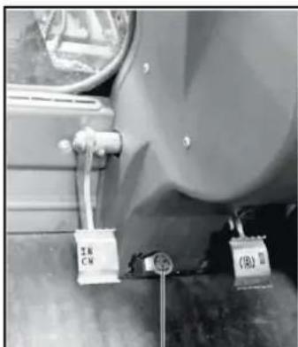
Clean the plug and coupling with a lint-free cloth before use.
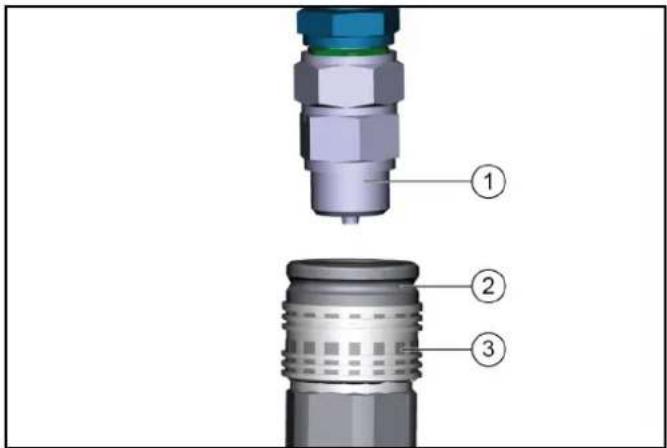
① Coupling connector
②Coupling sleeve
③Ring
- Pull the ring of the coupling sleeve downwards and hold.
- Press the coupling connector of the attachment hydraulic hose into the coupling sleeve.
- Release the coupling ring. Check that it is securely engaged.
- To decouple, pull the ring downwards, hold it and pull out the hydraulic hose.
9.2 Ballasting the vehicle
Note
The front axle of the vehicle must always be loaded with at least 30% of the net weight of the vehicle, and the rear axle must always be loaded with at least 30% of the net weight of the vehicle.
Before purchasing the attachment, check that these requirements are met by weighing the vehicle-attachment combination.
The following data is required for determining the total weight, the axle loads, the tyre loading capacity and the required minimum ballast:
- All weights in kg (weigh the vehicle if necessary)
• All dimensions in meters (m)
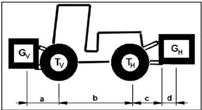
| TL (kg) = | Net | weight of the vehicle * | |
| TV (kg) = | Front axle load of the empty vehicle * | ||
| TH (kg) = | Rear axle load of the empty vehicle * | ||
| GH (kg) = | Total weight rear attachment / rear ballast | ** | |
| GV (kg) = | Total weight of front attachment / front ballast | ** | |
| a (m) = | Distance between front attachment(front ballast) centre of gravity and mid-dle of front axle, max. = 0.86 m | *** | |
| b | (m) = Wheelbase of the vehicle * *** | ||
| c | (m) = 0.56 | ||
| d | (m) = Distance between the centre of the equipment-side attachment point and the centre of gravity of the rear attach-ment / rear ballast | ** *** | |
* See chapter "Technical data"
** See operating instructions of the attachment
*** Measure
9.2.1 Calculation of the minimum front ballast for rear-mounted attachments
$$ G _ {V \min} = \frac {G _ {H} \times (c + d) - T _ {V} \times b + 0 , 2 \times T _ {L} \times b}{a + b} $$
- Enter the result into the table.
9.2.2 Calculation of the minimum rear ballast for front-mounted attachments
See the manufacturer's specifications for the value "x" or use a value of x = 0.45 if no specifications are available.
$$ G _ {H \min} = \frac {G _ {V} \times a - T _ {H} \times b + x \times T _ {L} \times b}{b + c + d} $$
- Enter the result into the table.
9.2.3 Calculation of the actual front axle load
$$ T _ {v t a t} = \frac {G _ {V} \times (a + b) + T _ {V} \times b - G _ {H} \times (c + d)}{b} $$
- If the necessary minimum front ballast weight (GV min) is not reached with the front attachment (GV) then the weight of the front attachment must be increased to the minimum front ballast weight.
- Enter the actual calculated permissible front axle load and the permissible front axle load specified in the work machine operating instructions into the table.
9.2.4 Calculation of the actual total weight
$$ \mathbf {G} _ {\text { tat }} = \mathbf {G} _ {\mathrm{v}} + \mathbf {T} _ {\mathrm{L}} + \mathbf {G} _ {\mathrm{H}} $$
- If the necessary minimum rear ballast weight (GH min) is not reached with the rear attachment (GH), then the weight of the rear attachment must be increased to the minimum rear ballast weight.
9.2.5 Calculation of the actual rear axle load
$$ T _ {H t a t} = G _ {t a t} - T _ {V t a t} $$
- Enter the result into the table.
9.3 Front mounting options
9.3.1 3-point mount (optional)
The 3-point mount is attached to the front power lift and secured with 2 bolts.
It has got one inclination adjustment system.
①3-point mount
②Lower link
③Fastening for top link
④Bolt for inclination adjustment
⑤Bolt for securing front power lift
Inclination adjustment
- Remove the bolt for the inclination function; the attachment is able to swing.
- If the attachment is completely raised, the device will be aligned horizontally.
9.3.2 Fitting the attachment on the 3-point mount
⚠ WARNING
Risk of injury due to attachments
Do not move or fit any attachments if persons are in the hazard zone.
△CAUTION
Risk of damage due to incorrect fitting
After fitting the attachment, check to see that the driver cabin or add-on parts are not damaged during the lifting process.
ATTENTION
Observe the graphics and mounting guidelines provided for preventing erroneous installation.
Note
Keep a sufficient gap to the driver cabin or superstructures. Any contact must be ruled out.
Bear in mind the weight of the attachment. Attach heavy superstructures as near as possible to the vehicle.
- Drive up to the attachment.
- Connect the lower link to the attachment.
- Fix the attachment in place using 2 bolts and secure the bolts with locking pins.
- Connect and secure the top link to the attachment.
Observe the following description pertaining to correct / erroneous installation of the top link.
Erroneous installation of the top link
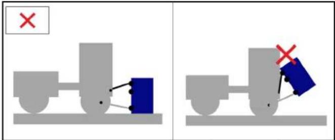
1 The upper connection (top link) of the vehicle for the attachment is not correctly installed. The angle to the lower mounting deviates too much.
2 If the attachment is raised in this way, this will lead to a sudden retraction towards the driver cabin and thus to damaging the windscreen, or other add-on parts.
3 The more the angle deviates from the upper to lower mounting, the more the attachment will be tilted backwards during the lifting process.
Correct installation of the top link
1 The upper connection of the vehicle for the attachment is correctly installed. The angle of the connection is much flatter than with an incorrectly installed connection. This prevents the driver cabin from being damaged when the attachment is being lifted.
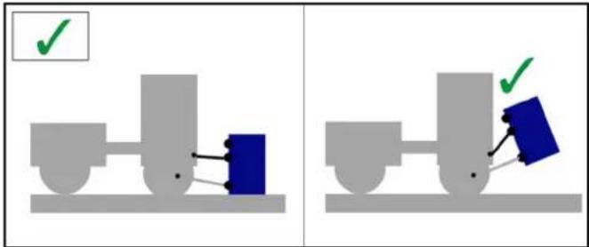
9.3.3 4-point mount (optional)
The 4-point mount is attached to the front power lift and secured with 2 bolts.
It has got one inclination adjustment system.
①4-point mount
②Central locking lever
③Lower mount
④Top mount
⑤Bolt for inclination adjustment
Inclination adjustment
- Remove the bolt for the inclination function; the attachment is able to swing.
- If the attachment is completely raised, the device will be aligned horizontally.
9.3.4 Fitting the attachment on the 4-point mount
⚠ WARNING
Risk of injury due to attachments
Do not move or fit any attachments if persons are in the hazard zone.
- Drive up to the attachment.
- Lower the front power lift far enough until the upper coupling points are beneath the mounts for the attachment.
- Pull the lever for the central lock upwards, and push it to the right in order to open the lock.
- Drive up to the attachment until the mounts come into contact.
- Cautiously move the front power lift upwards until the attachment is lifted into the mounts and fixed in place.
- Push the lever on the central lock to the left again; the lever must engage in the holder in order to lock the attachment.
9.3.5 Detaching the attachment on the 4-point mount
- Lift the attachment off the ground.
- Release the central lock.
- Lower the 4-point mount with front power lift far enough until the mounts of the attachment are exposed.
- Drive away from the attachment.
- Close the lever for the central lock again before the 4-point mount is raised upwards completely.
9.3.6 Front mounting frames
Certain attachments can be attached directly to the mounting frame for attachments.
natural_image
Top-down view of a vehicle chassis with labeled components (no text or symbols beyond labels)①Mounting frames
- Push the attachment into the mounting frames and secure using 2 bolts.
9.4 Mounting options at the rear of the vehicle
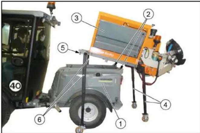
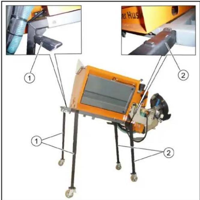
9.4.1 Attachment frame with tipping function (option)
Possible attachments on the attachment frame: Spreader, water drum or the grass / leaf vacuum container on a mower / vacuum combination.
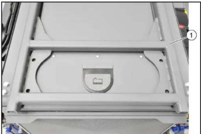
natural_image
Close-up of a mechanical component with a central recessed part and mounting holes, no visible text or symbols.①Attachment frame with tipping function
- The attachments are fitted on a Kärcher interchangeable frame or on an integrated interchangeable frame from the attachment manufacturer, and are fitted and secured on the attachment frame.
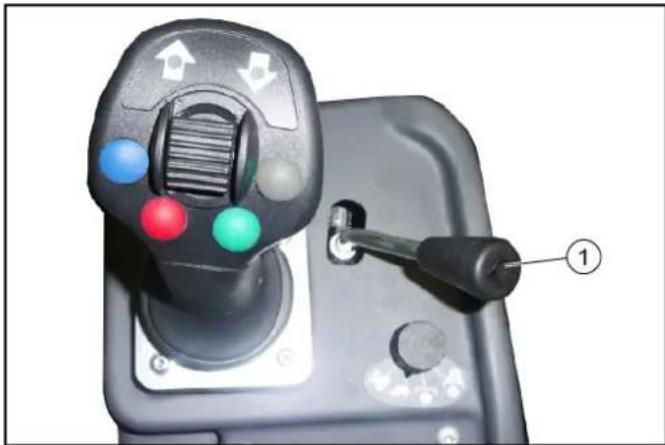
natural_image
Close-up of a game controller with colored buttons and a handle, labeled with number 1 (no text or symbols on the device itself)①Control lever
- The attachment frame is controlled using the control lever at the right of the joystick.
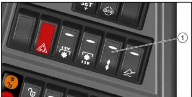
①Switch for "double-acting control hydraulics AUX rear" / "attachment frame with tipping function"
- To activate, switch the switch over to "attachment frame with tipping function".
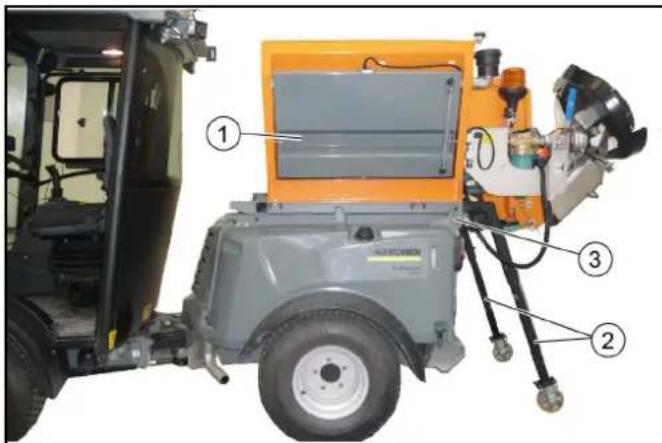
9.4.2 Mounting options on the attachment frame
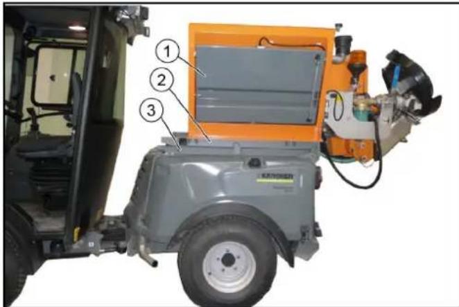
①Mounted spreader
②Interchangeable frame (integrated in the attachment)
③Attachment frame with tipping function
- Attaching / removing is described using the example of a mounted spreader.
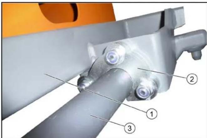
9.4.3 Setting the fixing
Note
The setting for the fixing of the interchangeable frame must only be made during first installation or when fitting to another carrier vehicle.

① Screw with nut
②Fixing hook (2x)
③Attachment frame
- Undo the nuts to the left and right by about 1 revolution.
- Fit the attachment to the attachment frame and secure it using retaining pins and retaining clips, see the following chapter9.4.4 Fitting the attachment to the vehicle.
- Completely lower the attachment frame.
- Press the fixing hook against the attachment frame as shown.
- Re-tighten the nuts to the left and right.
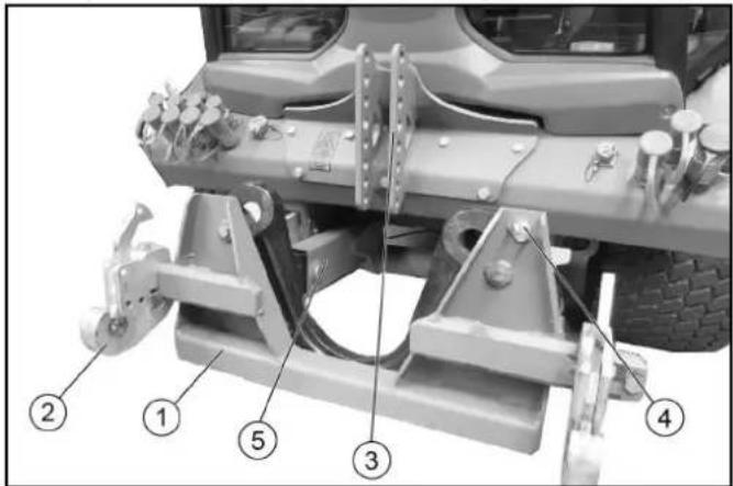
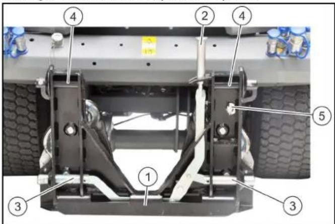
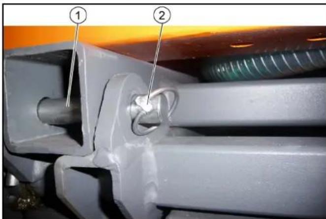
9.4.4 Fitting the attachment to the vehicle
① Vehicle rear
②Retaining pin with retaining clip (2x)
③Attachment
④Rear supports
⑤Fixing hook (2x)
⑥Front supports
- Remove the retaining pins from the attachment frame to the left and right (retaining pin and retaining clip are a part of the attachment frame).
- With the vehicle rear centred and parallel, (carefully) drive under the attachment standing on supports as far as you can go.
①Interchangeable frame for the attachment
②Fixing hook (2x)
③Attachment frame
- Cautiously lift the attachment frame until the front support feet come off the ground, whilst making sure that the fixing hooks engage in the attachment frame.
- Finally, check the secure fit of the fixing hooks.
- Remove the front supports from the attachment.
①Attachment
②Rear supports
③Locking device for attachment (2x)
6. Get in, and completely lower the attachment frame.
7. Remove the rear supports from the attachment.
①Retaining pin (2x)
②Retaining clip (2x)
-
Secure the attachment to the left and right (retaining pin and retaining clip are a part of the attachment frame). During first installation or when changing the carrier vehicle, the fixing must be set, see chapter 9.4.3 Setting the fixing.
-
Deal with the hydraulic and electrical connections after doing the fitting.
9.4.5 Removing the attachment from the vehicle
①Front supports
②Rear supports
- Completely lower the attachment frame.
- Disconnect the hydraulic and electrical connections prior to the dismantling.
- Remove the retaining pins to the left and right.
- Insert the two rear supports as far as they will go.
- Lift the attachment frame far enough until the front supports can be inserted.
- Get in, and completely lower the attachment frame.
- Insert the two front supports as far as they will go.
- Lower the attachment frame.
- Cautiously drive the vehicle out.
9.5 Rear mounting options
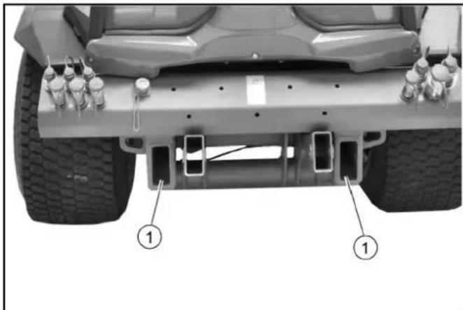
9.5.1 Rear mounting frames
Counterweights and certain attachments can be attached directly to the mounting frame for attachments.
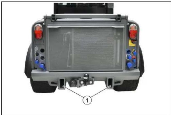
natural_image
Top-down view of a vehicle rear bumper with visible engine components and a numbered annotation (1) pointing to the front wheel.①Mounting frames
- Push the attachment into the mounting frames and secure using 2 bolts.
9.5.2 Tow bar
ATTENTION
Make sure when coupling and decoupling that nobody is in the hazard zone.
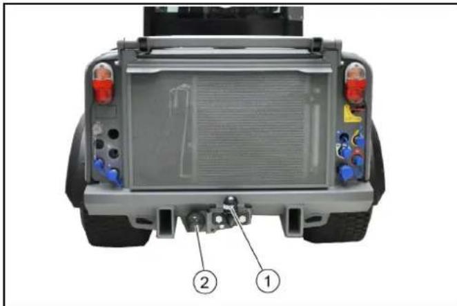
natural_image
Top-down view of a vehicle rear bumper with labeled parts (1 and 2), showing no text or symbols beyond labels.①Tow bar
②Trailer power socket
Note
For permissible support load and trailer load, see 16 Technical data.
Only trailers fitted with an inertia braking system may be coupled.
The support load depends on the trailer coupling and the tyres.
10 Transport
10.1 Loading the vehicle
△DANGER
Risk of injury due to incorrect transport
Mind the weight of the vehicle.
Slowly and carefully drive the vehicle onto the transport vehicle.
ATTENTION
Damage to vehicle
Do not load the vehicle with the crane.
Do not use a forklift.
- Slowly drive the vehicle onto the transport vehicle.
Note
If the vehicle is not ready for running, see Chapter 10.2
Towing the vehicle.
10.1.1 Fastening the transport lock to the articulated joint

①Bolt with safety cotter
②Transport lock
③Transport lock storage
- Pull out the safety cotters.
- Pull out both bolts.
- Remove the transport lock out from storage.
- Attach the transport lock.
- Insert the bolts.
- Lock the bolts with safety cotters.
10.1.2 Securing the vehicle
⚠ WARNING
Danger of accident
Secure the vehicle against slipping during transport.
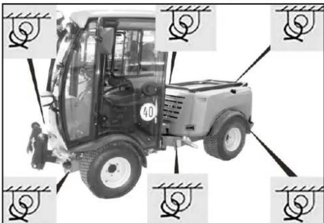
- Park the vehicle.
- Secure the vehicle with lashing straps on both sides of the illustrated fastening points.
10.2 Towing the vehicle
ATTENTION
Risk of damage due to incorrect towing
Towing a hydrostatically driven vehicle is possible only to a limited extent; mostly limited to a few metres. Therefore, only tow the vehicle out of the hazard zone of the moving traffic, and make sure you have transport facilities.
Only tow the vehicle at walking speed.
Approach slowly and not jerkily.
Only fasten the vehicle for towing purposes to the towing eye (front) or trailer coupling (rear).
Preferentially, use a suitable tow bar.
- In order to tow the vehicle, the hydraulic brake cylinders must first be released and the two bypass valves opened.
10.2.1 Fitting the towing eye
Note
The towing eye with retaining pin and locking pin can be found in the driver cabin.
In vehicles without EC type-approval, it is not in the scope of delivery, but can be ordered as accessories (order number 2.852-220.0).
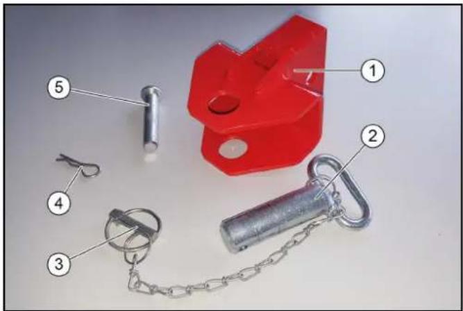
①Towing eye
②Retaining pin
③Locking pin
④Locking pin for bolt
⑤Bolt
- Take the towing eye out of the driver cabin.
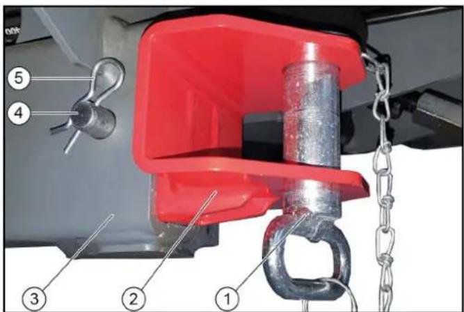
①Retaining pin with locking pin
②Towing eye
③Vehicle chassis
④Bolt
⑤Locking pin
2. Attach the towing eye at the front of the vehicle chassis on the right-hand side.
3. Insert the retaining pin into the towing eye and secure with the locking pin.
10.2.2Releasing the hydraulic brake cylinder
The nuts for releasing the brake cylinders are located to the left and right of the articulated joint.
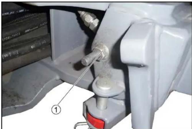
natural_image
Close-up of a mechanical assembly with a metallic component and a red button, no visible text or symbols①Hydraulic brake cylinder
- Release the nut on the hydraulic brake cylinder to the left and right.
10.2.3 Opening the bypass valves
The bypass valves are located on the bottom side, in the front area of the rear end.
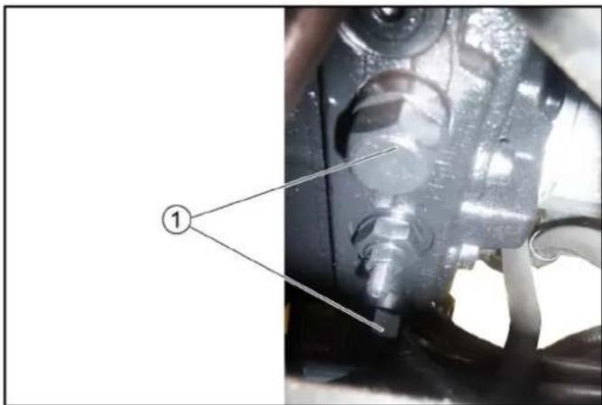
natural_image
Close-up of mechanical components with a numbered label pointing to a component (no readable text or symbols)①Bypass valve
- Unscrew the bypass valves 3 revolutions (width across flats 24 mm).
- Fasten the tow rope on the towing eye at the front or rear.
- Pull the vehicle slowly onto the transporting vehicle.
- After towing, tighten the nuts on the brake cylinder again (tightening torque 70 Nm) and close the bypass valves.
11 Storage
⚠ WARNING
Risk of injury and damage
Note the weight of the device.
- Change the engine oil and engine oil filter.
- If there is a danger of frost, check whether there is enough antifreeze in the coolant.
- Clean the vehicle inside and out.
- Place the vehicle in a dry, protected place on an even surface.
- Turn the ignition key to the "Stop" position and remove it.
- Switch off the main switch.
- Jack up the vehicle when storing over one month.
- Disconnect the battery.
- Charge the battery every 2 months.
12 Care and maintenance
12.1 General safety instructions
⚠ WARNING
Risk of fatal injury from moving traffic
Prior to maintenance or repair work, get the vehicle out of the hazard zone of the moving traffic, and wear a warning vest.
△DANGER
Crush hazard
When working under raised attachments, ensure these are always mechanically locked (shimming).
⚠ WARNING
Risk of injury and damage
Keep away from the drive area. Be aware of the engine after-running time after switching off (3-4 seconds).
Disconnect the battery before working on the electrical system.
△CAUTION
Risk of injury due to inadvertently starting up vehicle.
Before you clean and service the vehicle, or exchange parts or adjust them to a different function, switch off the vehicle and remove the ignition key.
△CAUTION
Risk of burns from hot surfaces and operating fluids
Allow the vehicle to cool down sufficiently prior to all maintenance and repair work.
ATTENTION
Do not let fluids such as engine oil, hydraulic oil, brake fluid, diesel or coolants end up in the environment. Dispose of these fluids in an environmentally friendly manner.
ATTENTION
Repair work may only be carried out by authorised customer service centres or by qualified staff in this area who are familiar with all relevant safety instructions.
Welding work on the vehicle or vehicle chassis is not allowed.
12.2 Service indicator
The service indicator lights up when the respective maintenance needs to be done.
The service indicator flashes on the display:
- after 50 operating hours when the initial inspection needs to be performed.
- Next service after 250 operating hours.
- Then every 500 operating hours.
Note
The service indicator must be reset by the Customer Service.
12.3 Maintenance intervals
Note
In order to preserve warranty claims, all servicing and maintenance work during the warranty period has to be performed by an authorised Kärcher Customer Service, in accordance with the inspection check list.
- Daily before starting operation, see chapter 7.2 Safety check.
- Lubricate all bearings after washing the vehicle.
- If necessary have the safety checks according to the applicable local regulations performed by the Customer Service department.
- The intervals for inspection and maintenance work to be performed by the customer are listed in the following table.
Additional maintenance work is to be carried out by the Customer Service department in accordance with the inspection checklist after 250, 500 (annually), 1000, 1500 or 2000 operating hours. Please inform the Customer Service department in time.
* depending on which occurs first
12.4 Vehicle maintenance plan (to be carried out by customer)
| Pos. | Assembly | Activity | Daily | Weekly | every 500 hours or once-a-year* |
| 1 Cabin dust filter Check for contamination. | Clean or renew a contaminated dust filter. | X (depending on environmental conditions) | X | ||
| Renew X (earlier if | needed) | ||||
| 2 | Steering | Visual | inspection | ||
| Check the bearings on the steering cylinder for play. | X | ||||
| 3 Coolant expansion reservoir Check the coolant level. | X | ||||
| Check the mixing ratio water / antifreeze. | X | ||||
| 4 | V-belt | Check the tension. | X | X | |
| 5 | Screw connections | Visual inspection; tighten if needed. | X | X | |
| 6 Engine air filter Check for contamination. | X | ||||
| Clean or renew contaminated engine air filter. | |||||
| Renew X (earlier if | needed) | ||||
| 7 Engine oil Check the oil level prior to travel commencement. | X | ||||
| Renew X | |||||
| 8 Engine oil filter Renew X | |||||
| 9 | Hydraulic oil tank | Check the hydraulic oil level. | X | X | |
| 10 | Hydraulic couplings and connections | Check for leaks. | X | X | |
| 11 Battery Check the battery for voltage, and is firmly in place and leak-proof. | X | X | |||
| Check the electrolyte level and electrolyte density in the cells (only low-maintenance battery). | X | ||||
| Check the battery poles for oxidation, brush off if necessary, and lubricate with terminal grease. Make sure the connection cables are firmly in place. | |||||
| 12 Exhaust system Check the condition of the connecting elements and make sure they are firmly in place. | X | X | |||
| Visual inspection of the exhaust system for cracking and leaks. | X | ||||
| 13 Parking brake Check it is working correctly and is correctly set | X | X | |||
| 14 Radiator Visual inspection of engine coolant, charge air and hydraulic oil cooler for damage, firm fit, tightness and contamination; clean if necessary. | X | X | |||
| Check the coolant level. Check the mixing ratio water / coolant. | X | ||||
| Check the coolant hoses for leaks and damage. | X | ||||
| 15 Tyres Check the condition and filling pressure. X X | |||||
| 16 Wiping water container Check the filling level. X X | |||||
| 17 Lighting and horn Check for correction function. X X | |||||
| 18 Air-conditioner / heater Check for functionality and leaks. Disinfect the evaporator for the air-conditioner. | X | ||||
| 19 Warning sticker Check the legibility, replace if necessary. | X | ||||
| 20 Dust caps and covers for hydraulics Check, and replace any missing or damaged ones. | X | ||||
| 21 Hoses and cable clamps Visual inspection of all hydraulic connections that they are correctly fitted and leakproof. | X | X | |||
| 22 Fuel lines and connections Check for leaks. X X | |||||
| 23 Bowden cables and moving parts Check for freedom of movement. | X | ||||
| 24 Alternator Clean (not with high-pressure cleaner) | X | ||||
| 25 Electrical cables Check for damage. | X | ||||
| 26 Bearings / lubrication points Lubricate, see chapter 12.5 Lubrication plan | X | ||||
12.5 Lubrication plan
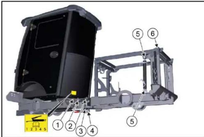

| Lubrication point Quanti-ty | Interval | |
| 1 Central lubricating strip forSlew bearingLifting cylinder for front power liftFront bearing for steering cylinder | 1 Daily | |
| 2 Articulated joint at centre of vehicle | 2 Daily | |
| 3 Steering cylinder 2 Daily | ||
| 4 Lower bearing for articulated joint | 1 Daily | |
| 5 Lifting cylinder for lifting plat-form | 4 Every 25 h | |
| 6 Slew bearing lifting platform 2 Daily | ||
| 7 Accelerator 1 Every 100 h | ||
| 8 Brake pedal deflection lever 1 Every 100 h |
1 Use high-grade multi-purpose grease.
2 Lubricate the grease nipples in accordance with the lubricating intervals (Table) using a grease gun.
3 Keep the V-belt clean and free of grease.
12.6 Preparing for maintenance work
- Park the vehicle on a level surface.
- Set the engine speed to idle mode.
- Switch off the ignition and remove the ignition key.
- Secure the vehicle against rolling away.
- Set the main switch to position "0".
12.7 Maintenance work
12.7.1 Raising the attachment frame
Note
The raised attachment frame is automatically secured by a special valve on the vehicle side. It is not necessary to secure it manually.
- Set the switchover valve to the attachment frame position.
- Completely raise the attachment frame.
12.7.2Panels / covers
⚠ WARNING
Risk of burns from hot surfaces
Allow the vehicle to cool down sufficiently prior to removing the panels / covers.
Note
In order to carry out various maintenance work, the panels / covers have to be removed.
12.7.3Side covers
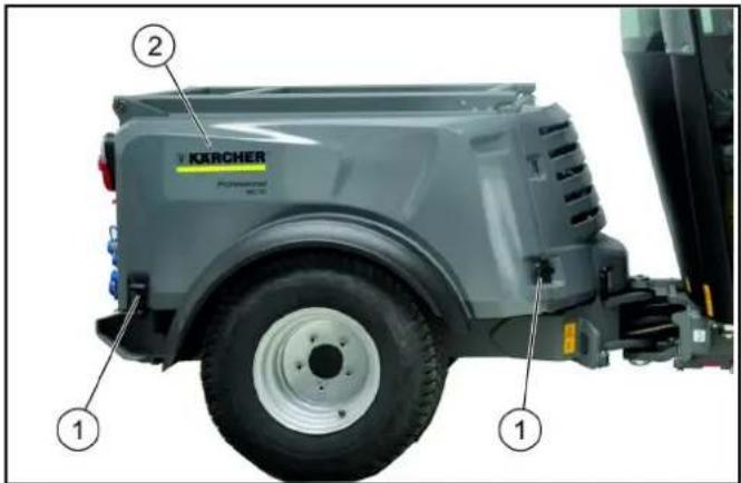
①Lock for side cover
②Side cover
Removing the side cover:
1 Open both locks.
2 Lift the side cover and pull it out to the side.
Attaching the side cover:
1 Insert the side cover at the side.
2 Mount the side cover at the upper edge and into the fixing slot.
3 Slide the side cover into the correct position and secure it using the locks.
12.7.4Front cover
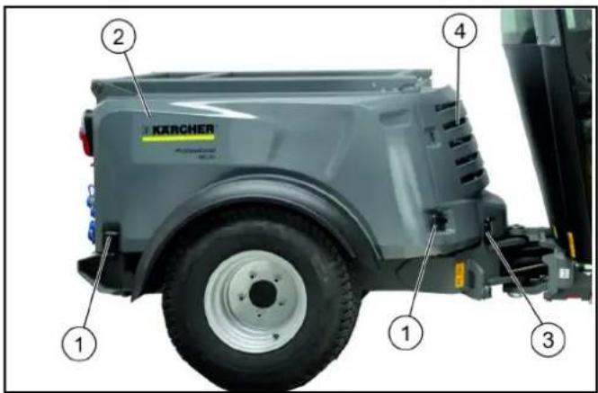
①Lock for side cover
②Side cover
③Lock for front cover
④Front cover
Removing the front cover:
1 Remove both side covers.
2 Open the left and right lock on the front cover.
3 Lift and remove the front cover.
Attaching the front cover:
1 Mount the front cover and fix it in place using both locks.
2 Install both side covers.
12.7.5Radiator protective grille
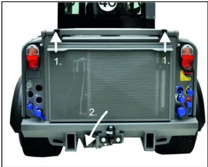
Removing the radiator protective grille:
1 Lift the radiator protective grille at the top.
2 Move out the lower part
3 Remove the radiator protective grille in a downward direction.
Attaching the radiator protective grille:
1 Engage the radiator protective grille at the bottom, then snap shut at the top.
12.7.6Removing / installing the battery
△DANGER
Risk of injury
Observe the safety instructions on the handling of batteries.
Disconnect the minus terminal first when removing the battery.
Protect the battery terminals and terminal clamps with a sufficient quantity of terminal grease.
Removing the battery
-
Remove the covering caps from the terminal clamps.
-
Release the terminal clamp (black cable) on the minus terminal (-).
-
Release the terminal clamp (red cable) on the plus terminal (+).
-
Unscrew the bracket on the battery base.
-
Take the battery out of the battery holder.
Installing the battery
-
Fit the battery into the battery holder.
-
Screw the bracket on the battery base tight.
-
Connect the terminal clamp (red cable) to the plus terminal (+).
-
Connect the terminal clamp (black cable) to the minus terminal (-).
-
Plug the cover caps onto the terminal clamps.
12.7.7Charging the battery
△DANGER
Risk of injury
Only charge the battery with a suitable charger.
Observe and follow the instructions for use from the charger manufacturer.
Observe the safety instructions on the handling of batteries.
-
Disconnect the minus terminal at the battery.
-
Connect the charger to the battery.
-
Insert the mains plug and switch on the charger.
-
Charge the battery with as small a charging current as possible.
-
After charging, disconnect the charger from the mains first and then from the battery.
12.7.8Changing a wheel
△DANGER
Risk of fatal injury from flowing road traffic
Bring the vehicle out of the hazard zone of flowing road traffic before starting any repair work.
Switch on the warning flashers.
Erect a warning triangle.
Don warning clothing.
△CAUTION
Danger of accident
Ensure that the ground is level and solid. If necessary, place a large-scale, stable surface under the jack.
ATTENTION
Perform the wheel change only if you are familiar with the necessary steps for changing a wheel. Otherwise, seek expert assistance.
Use only suitable and undamaged tools for changing a wheel.
Use a suitable commonly available vehicle jack.
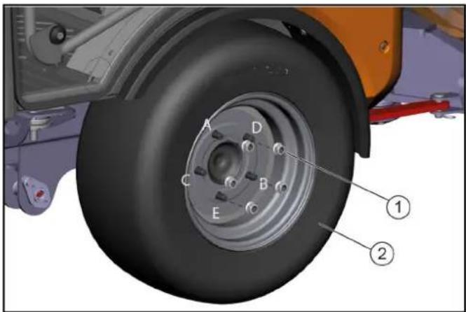
①Wheel nuts
②Wheel
-
Park the vehicle on level and solid ground.
-
Engage the parking brake and additionally secure the vehicle against rolling away.
-
Secure the articulated joint.
-
Remove the ignition key.
-
Use a suitable tool to release the wheel nuts by approx. 1 turn.
-
Fit the jack to the (marked by the corresponding symbol) mounting point at the front or rear wheel and raise the vehicle with the jack.
-
Additionally support the vehicle with safety stands.
-
Unscrew the wheel nuts.
-
Remove the wheel.
- Clean any dirty wheel nuts and threaded studs.
- Fit the new wheel and tighten all wheel nuts lightly all the way to their end stops.
- Tighten the wheel nuts in the specified order (A - E) step by step.
- Finally, tighten the wheel nuts in the specified order using a correctly working torque wrench to 180 Nm.
- Pull out the safety stands and lower the vehicle with the jack.
12.7.9 Checking the engine oil level
△CAUTION
Danger of burns
Allow the vehicle to cool down long enough so that there is no longer a risk of burns.
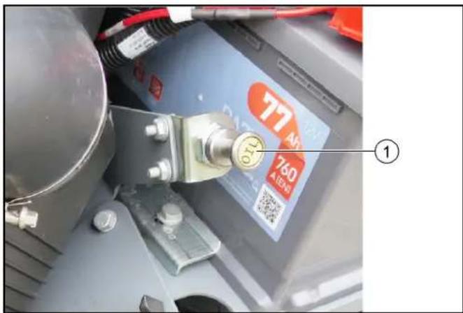
①Oil dipstick
- Park the vehicle on a level surface.
- Switch off the ignition and remove the ignition key.
- Remove the right-hand side cover.
- Pull out the oil dipstick.
- Wipe the oil dipstick and insert it.
- Pull out the oil dipstick.
- Read off the oil level on the oil dipstick. If the oil level is below the lower mark (MIN), top up the engine oil.
12.7.10 Topping up the engine oil
△CAUTION
Danger of burns
Allow the vehicle to cool down long enough so that there is no longer a risk of burns.
△CAUTION
Risk of damage
An excessive high oil level leads to engine damage. If the oil level is higher than the upper marking on the oil dipstick, then oil must be drained until the correct oil level is reached.
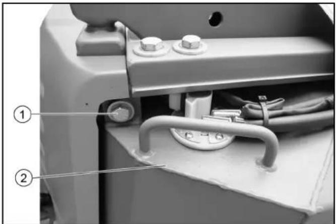
natural_image
Close-up of a mechanical device showing internal components with numbered labels (1 and 2), no readable text or symbols beyond labels.①Screw for fuel tank
②Fuel tank with handle
- Remove the left-hand side cover.
- Unscrew the screw for the fuel tank.
- Pivot the fuel tank outwards using the handle.
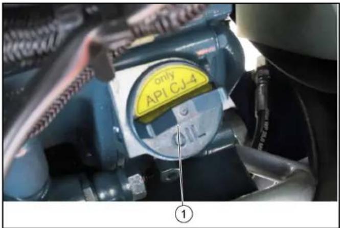
①Oil filler cap
- Remove the oil filler cap.
- Top up the engine oil.
For the engine oil specifications, see chapter.
Do not fill the engine oil above the "MAX" mark.
- Check the engine oil level after 5 minutes.
Top up the engine oil if necessary.
12.7.11 Changing the engine oil and engine oil filter
△DANGER
Risk of burns from hot engine oil!
Allow the vehicle to cool down long enough so that there is no longer a risk of burns from hot engine oil and the engine oil filter.
Note
A warm engine facilitates the draining of engine oil.
- Park the vehicle on a level surface.
- Provide a catch pan for at least 10 litres of oil.
- Switch off the engine.
- Remove the oil filler cap.
- Unscrew the oil drain plug.
- Drain the engine oil.
- Unscrew the engine oil filter.
- Clean the mount and sealing surface.
- Coat the seal of the new engine oil filter with oil.
- Screw in the new engine oil filter and manually tighten it sufficiently.
-
Renew the sealing ring for the oil drain plug and tighten the oil drain plug to 60 Nm.
-
Pour in the engine oil.
For the fill volume and oil grade, see chapter.
-
Close the oil filler cap.
-
Allow the engine to run for approx. 30 seconds.
-
Wait at least 5 minutes.
-
Check the engine oil level.
Top up the engine oil if necessary.
-
Check the tightness of the sealing ring and engine oil filter.
-
Dispose of waste oil in an environmentally friendly manner (collection points).
12.7.12 Bleeding the fuel system
Note
If the fuel tank was run empty or the fuel filter was changed, then the fuel system must be bled.
-
Make sure that the fuel tank is filled.
-
Turn the ignition key for 2 to 5 minutes in position I until the fuel pump audibly runs quietly.
12.7.13 Checking the hydraulic oil level and topping up the hydraulic oil
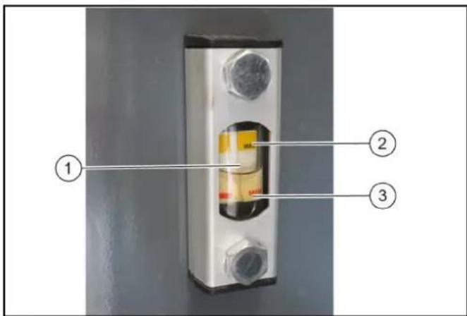
①Hydraulic oil level display
②Maximum hydraulic oil level
③Minimum hydraulic oil level
- Check the hydraulic oil level.
Note
The hydraulic oil level must be between the upper (MAX) and lower mark (MIN).
- Top up the hydraulic oil if necessary.
Note
Lacking hydraulic oil can be topped up using a special tool which is connected up to the leakage coupling on the vehicle. If required, request the order no. at Kärcher or have Kärcher Customer Service do the topping up. For the hydraulic oil grade, see chapter.
12.7.14 Checking the coolant level and topping up the coolant
△CAUTION
Risk of burns due to hot components
Do not touch any parts of the cooling system when the engine is hot. Open the cooling system only when the engine is cold.
ATTENTION
Material damage due to incorrect coolant
Top up the coolant only when the engine is cold.
Use the water frost protection mixture.
Do not mix the antifreeze.
Only use soft or distilled water.
For the coolant, see chapter.
Note
Check the filling level when the engine is cold.
When the engine is warm, the coolant level could also be just over the upper mark.
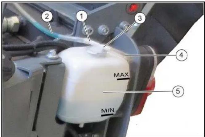
①Connection adapter, long
②Hose leading to radiator
③Expansion reservoir lid
④Breather hose
⑤Expansion reservoir for coolant
-
Remove the left-hand side cover 12.7.3 Side covers.
-
Check the filling level in the expansion reservoir.
Note
The coolant level must be between the upper (MAX) and lower (MIN) mark.
-
Top up fresh coolant if necessary.
-
Also check the filling level in the radiator, see chapter.
-
If the expansion reservoir is totally empty, top up the radiator first.
12.7.15 Topping up the coolant in the radiator
⚠ WARNING
Risk of injury due to pressurised cooling water
Do not unscrew the radiator cap until the cooling system has cooled down and is no longer under pressure.
△CAUTION
Risk of burns due to hot components
Do not touch any parts of the cooling system when the engine is hot. Open the cooling system only when the engine is cold.
ATTENTION
Material damage due to incorrect coolant
Top up the coolant only when the engine is cold.
Use the water frost protection mixture.
Do not mix the antifreeze.
Only use soft or distilled water.
For the coolant, see chapter.
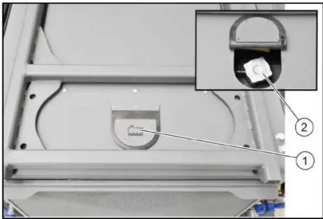
natural_image
Close-up of a mechanical device with an inset showing a component inserted into a housing (no visible text or symbols)①Radiator cap cover
②Radiator cap
- Tilt up the radiator cap cover.
- Turn the radiator cap one click to drain pressure from the radiator.
- Unscrew the radiator cap when the radiator has depressurised.
- Slowly fill the radiator bubble-free up to the outlet for the coolant expansion reservoir.
- Screw the radiator cap on tight.
- Refill the coolant expansion reservoir. See chapter 12.7.14 Checking the coolant level and topping up the coolant.
12.7.16 Cleaning and replacing the air filter MIC 70
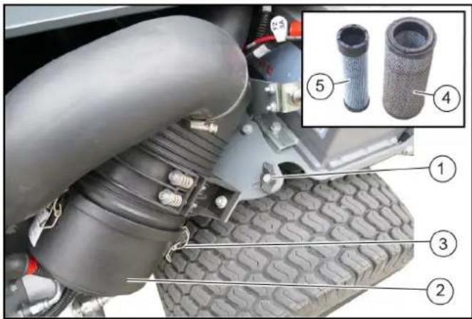
①Wing screw
②Air filter housing
③Lock (3x)
④Filter cartridge
⑤Safety cartridge
- Remove the right-hand side cover.
- Undo the wing screw, do not unscrew.
- Pivot the complete air filter unit outwards as far as it will go.
- Tighten the wing screw.
- Open the locks on the air filter housing.
- Remove the air filter housing.
- Pull out the filter cartridge and safety cartridge.
- Clean the air filter housing on the inside.
- Knock the dust out of the filter cartridge on a hard surface.
Do not blow out the filter cartridge with compressed air.
- Check that the filter cartridge and sealing surfaces are clean and undamaged.
Renew a heavily soiled or damaged filter cartridge.
- Renew the safety cartridge. Do not re-use a used safety cartridge.
- Insert the cleaned filter cartridge.
13.Fit the air filter housing. - Close the lock on the air filter housing.
- After assembly, pivot the complete air filter unit inwards and tighten it using the wing screw.
- Attach the right-hand side cover.
12.7.17 Changing the dust filter on the outer cabin
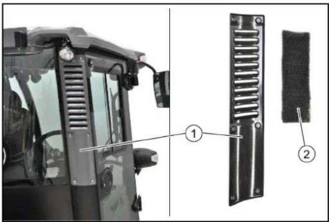
①Cover
②Dust filter
Note
Fine filter filter grade F8 (available as option)
- Unscrew the 6 screws for the cover.
- Remove the cover.
- Take out the dust filter.
- Blow out the slightly contaminated dust filter using compressed air (reduced pressure). Renew severely contaminated dust filter.
- Insert the new or cleaned filter.
12.7.18Changing the dust filter on the inner cabin
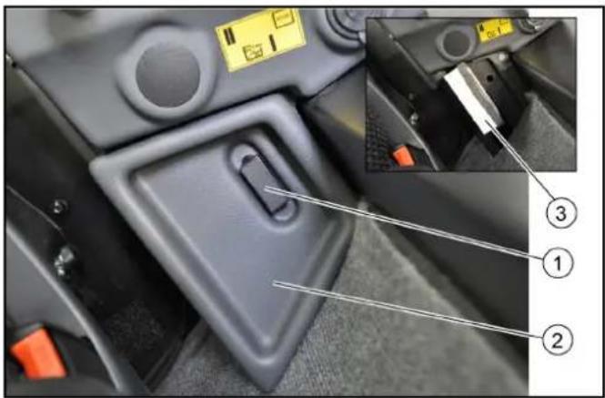
①Clamping lever
②Cover
③Dust filter
Note
Fine filter filter grade F8 (available as option)
- Release the clamping lever.
- Remove the cover in an upward direction.
- Take out the dust filter.
- Replace the dust filter.
Check that the seal and dust filter are correctly fitted during installation.
-
Attach the cover.
-
Actuate the clamping lever.
12.7.19 Changing the dust filter behind the driver's seat
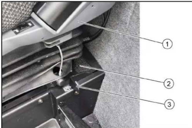
①Driver's seat
②Dust filter
③Air recirculation lever
- Push the driver's seat completely forwards.
- Take out the dust filter.
- Replace the dust filter.
- Push the driver's seat backwards.
12.8 Cleaning
△CAUTION
Risk of injury and damage
Always secure the tipping mechanism.
- Park the vehicle on a level surface.
- Switch off the ignition and remove the ignition key.
- Apply the parking brake.
- Switch off the main switch.
12.8.1 Cleaning the vehicle
Clean the vehicle daily after finishing work.
△CAUTION
Risk of damage through incorrect cleaning
The articulated joint, tyres, radiator fins, hydraulic hoses and valves, seals, electrical and electronic components must not be cleaned using a high-pressure cleaner.
Observe the respective safety regulations when cleaning the vehicle with a high-pressure cleaner.
Do not use aggressive cleaning agents.
Wash the vehicle only when the engine is switched off to protect the air filter.
- To avoid a risk of fire, check the vehicle for escaping oil and fuel. Have leaks repaired by Customer Service.
- Clean all plant residues and oil from the engine, muffler, battery and fuel tank to avoid a risk of fire.
- If necessary, clean the engine with a brush, compressed air or with low water pressure if necessary.
- Clean the wheel mudguards.
12.8.2 Cleaning the radiator
ATTENTION
Overheating due to contamination
Always keep the radiator grille, suction mesh and blower clear of damage, plant residues and other types of contamination.
- Remove the radiator protective grille. see chapter 12.7.5 Radiator protective grille
-
Remove coarse dirt deposits from the engine radiator, hydraulic oil cooler and air-conditioner radiator (option).
-
Clean the radiator with a soft brush, compressed air (max. 5 bar) or with low water pressure.
12.9 Fuses MIC 70
| Fuse | Consumer | Fuse | Consumer | Fuse | Consumer |
| F015A | Right position lightsRight license plate lightBacklight multilinstrument | F1415A | Extra controllerExtra CANSeat heating | F2510A | MAF sensorDisplayExtra brake |
| F025A | Left position lightsLeft license plate lightElectrical PTO front | F1510A | Power supply 3 | F2615A | H1 AC2 pumpSpeed selectionMode switchBrake pressure switchFNR switchReverse buzzerPark brakeFree wheel valveEngine air filterHydraulic oil filterHydraulic oil temp. |
| F1615A | WiperWasher pumpHornDifferential lockDump valve | ||||
| F0310A | Fuse F01Fuse F02 | ||||
| F0415A | Hazard lightsInferior light | ||||
| F0530A | Heated windshieldHeated mirrors | F1730A | FloatvalvesPTO valvesWeight transfer valvesFrontloader lock valve | ||
| F0620A | Electrical PTO frontElectrical PTO rear | ||||
| F0715A | Power supply 1 | F1820A | Air condition | F2710A | Ignition |
| F0830A | Seat compressorStop solenoid pull | F195A | EGR valveEngine diagnostic connector | F285A | Ignition |
| F0920A | Low beamHigh beamSwitch high/low roadlights | F2010A | Cabin 12V socket frontCabin 12V socket rear | F2925A | Engine ECUEngine sensorsFuel pump |
| F2115A | Rocker switch lightsElectrical change valvesFrontloader change valveLoad damping valvesRadio | F3040A | Preheat | ||
| F3110A | Diagnostic connectorDisplay | ||||
| F1030A | Worklights frontWorklights rearRotating beacon | ||||
| F1120A | Change valve rearLeak valveLeak valve load platform | F2210A | Control module | F322A | Radio constant feed |
| F1210A | Power supply 2 | F2310A | Cruise controlBrake lightsReverse pressure switch | F335A | Start indication |
| F1315A | Direction lightsMulti instrumentSpeed indicatorSpeedometer | F247.5A | AlternatorSeat switchFuel pumpRear view camera | F3450A | Starter |
- The fuses are located on a board behind the cover, on the right-hand side of the driver cabin.
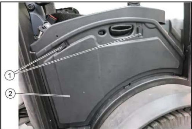
①Clamping lever
②Bar cover
2. Open the right-hand door of the driver cabin.
3. Actuate the clamping lever.
4. Remove the cover.
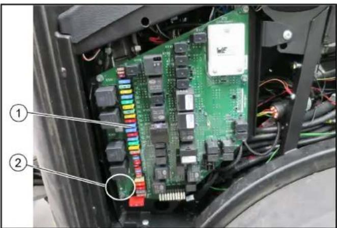
natural_image
Interior view of an electronic device showing a green circuit board with multiple connectors and wiring, labeled with numbers 1 and 2 (no readable text beyond labels)①Fuses
②Fuse tester with green LED
Note
Only works when the main switch is switched on
5. Pull out the supposedly defective fuse.
- Insert the fuse in a fuse tester, and check it. If the green LED lights up, then the fuse is not damaged. If the green LED does not light up, then the fuse is defective.
- Replace a defective fuse with a new fuse using the nominal value specified in the table.
- Attach the cover.
- Actuate the clamping lever.
- Close the door.
13 Regeneration process MIC 70
⚠ WARNING
Risk of burns due to the regeneration process
Only start manual regeneration in non-flammable areas.
During the regeneration process, the deposited soot particles will be burned and very hot exhaust gases (up to 600 °C) could escape.
13.1 Description of regeneration
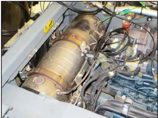
natural_image
Interior view of a vehicle engine bay with visible hoses, springs, and internal components (no text or symbols)The vehicle is equipped with a diesel particulate filter.
- The diesel particulate filter holds back the soot particles until they are burned at very high temperatures; this process is called regeneration. The regeneration process is carried out either automatically in driving mode but can also be started manually if required.
- The more frequently the vehicle is driven at high speeds or with loads, the less often will a regeneration process have to take place.
- The regeneration process takes place in various stages, depending on the stored amount of soot.
- The regeneration process can be preselected:
or (locked). The settings can be selected when the start display is booting up. - If
is selected, the control electronics automatically start the regeneration process if there are too many soot particles in the diesel particulate filter. - If
(locked) is selected, automatic regeneration is prevented and only is possible. The vehicle needs to be parked for .
Note
A detailed description of the regeneration process can be found in the following chapters.
13.2 Regeneration

This display lights up during automatic regeneration.

The display also temporarily lights up during the regeneration process.
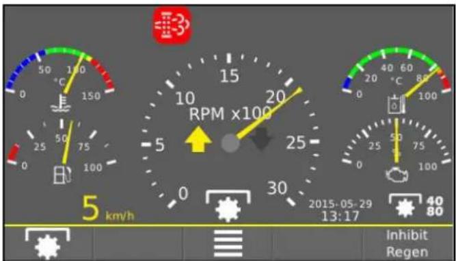
13.3 Regeneration

If the amount of soot particles in the diesel particulate filter necessitating regeneration is reached, then this will be shown together with the text message in the display.
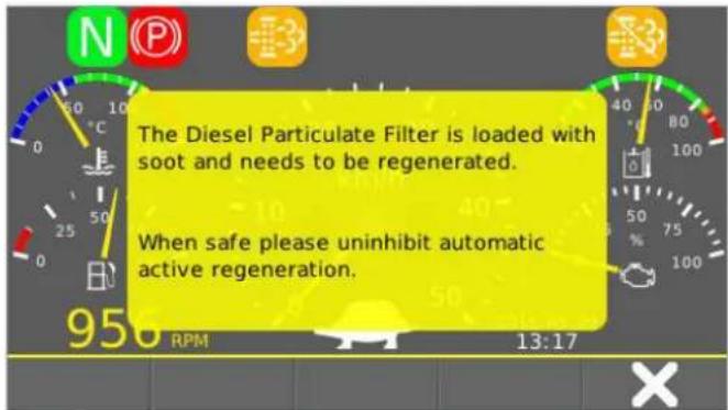
Stage 1: Press
13.4 Regeneration

If automatic mode is disabled, or the control electronics cannot start the regeneration process, the display will flash and text messages will appear.
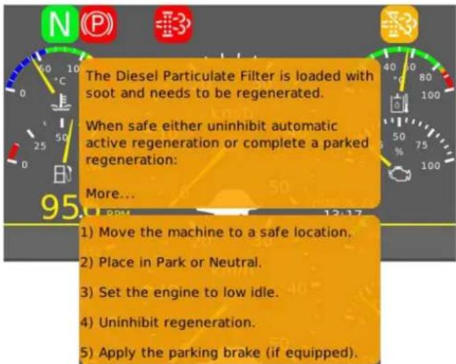
Stage 2: Automatic regeneration is now still possible or starting a
Note
The regeneration process
13.5 Regeneration
ATTENTION
By now at the latest, the regeneration process has to be started.
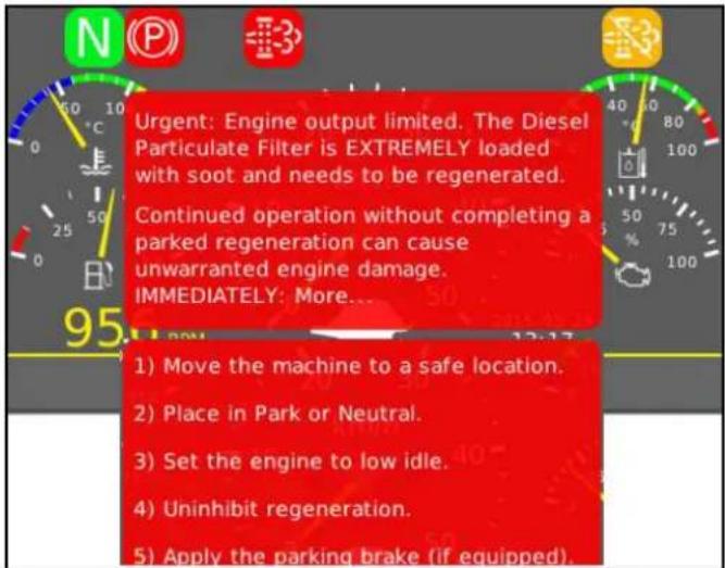
Stage 3: Only a
Note
The regeneration process
13.6 Regeneration
ATTENTION
Regeneration must be carried out by Kärcher-Service or by an authorised Kubota workshop.
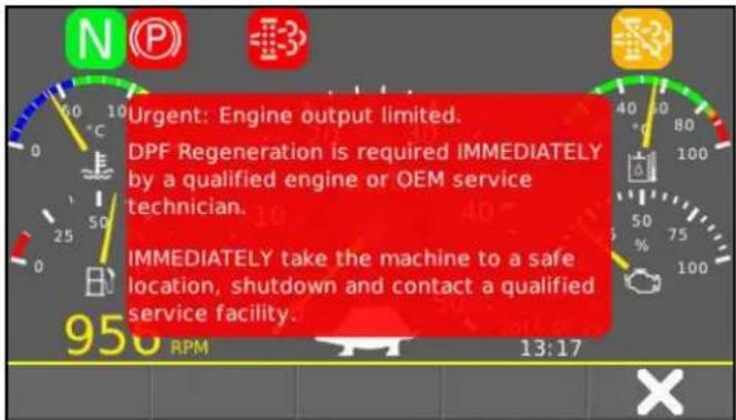
Stage 4: The vehicle can only drive at a limited speed. IMPORTANT: Drive the vehicle to the next safe place and park it.
13.7 Regeneration
ATTENTION
Regeneration is no longer possible. The diesel particulate filter must be exchanged and the control program needs a restart. This is only possible through Kärcher Service or through an authorised Kubota workshop.
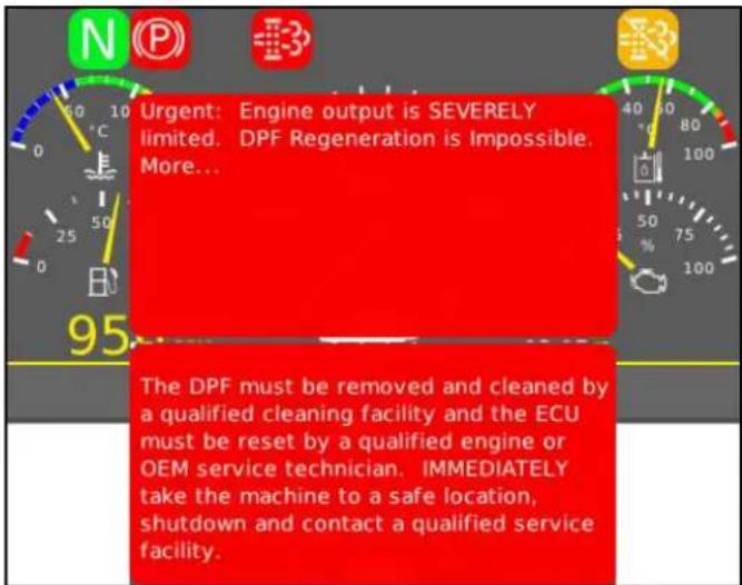
Stage 5 and last stage: The vehicle can only drive at a limited speed.
IMPORTANT: Drive the vehicle out of the hazard zone of the traffic, and to the next safe place and park it.
13.8 Regeneration
Regeneration is only possible if the following conditions are met. As soon as a condition is changed, the regeneration process will stop.
- Neutral position
- Parking brake activated (automatic in neutral position)
• No display of error codes
• Accelerator not actuated
ATTENTION
Never interrupt the regeneration process, unless it is urgently needed!
- Drive to a safe place.
- Park the vehicle in neutral position.
Text message:
- Select idle speed.
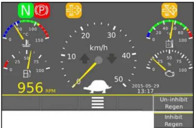
- Depending on the display, press
or .

- Navigate to the menu
in order to start the regeneration process.
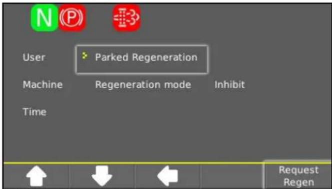
- Press
.

- The text message
appears in the display.
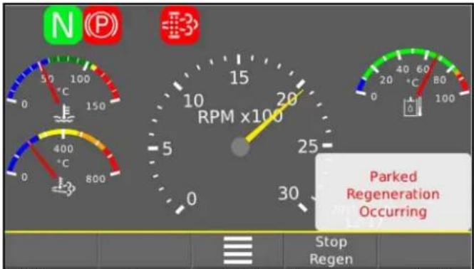
- If the request is successful, the display automatically switches over. The control unit increases the speed to 2000 rpm in order to, when necessary, increase the engine temperature, and switches permanently to regeneration.
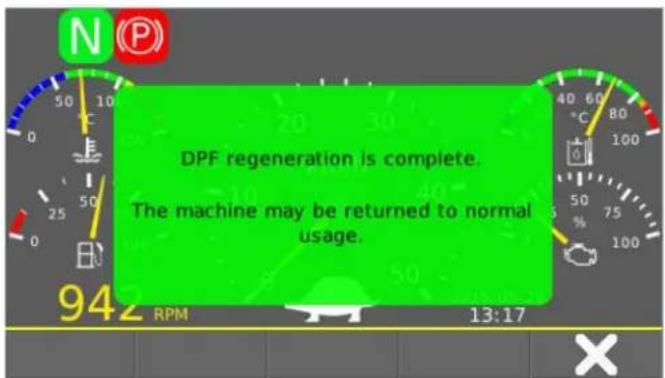
- After the regeneration process has expired, the engine runs at idle speed and the following text message appears.
Confirm message with
.
14 Troubleshooting guide
You can remedy minor faults using the following overview. If in any doubt, please contact your authorised Customer Service.
△DANGER
Risk of electric shock
Switch off the vehicle before carrying out any care and maintenance work, and remove the key.
Repair work and work on electrical components must only be performed by your authorised Customer Service.
14.1 Malfunctions with MIC 70 display
| Malfunction Cause Remedy | ||
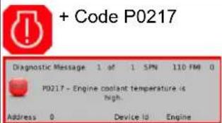 | Engine temperature too high | ● Set the engine speed to idle mode.● Clean the radiator.● Check the level of coolant in the engine.If the warning light does not go out within 5 minutes, switch off the engine and call Customer Service. |
 | Hydraulic oil temperature too high | ● Operate the engine in idling mixture (supply) until the warning light goes out. |
 | Hydraulic oil temperature too low | ● Cautiously warm up the engine until the warning light goes out. |
 | Battery is not charging ● Call Customer Service. | |
 | Fault has many causes ● Call Customer Service. | |
 | Fault in the drive ● Call Customer Service. | |
Code P0217 Fault has many 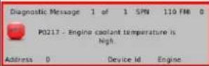 | causes ● Call Customer Service. | |
14.2 Malfunctions without display
| Malfunction Remedy | |
| Vehicle does not start | Check / charge the battery.Switch on the main switch.Sit in the driver's seat (seat contact switch is activated).Travel direction selector switch on the joystick to central position.<Neutral / Stop>.Fill up fuel, bleed the fuel system.Check, clean / replace the fuel filter.Check the fuel connections and lines.Contact an authorised Customer Service department. |
| Motor running irregularly | Clean/replace the air filter.Check, clean and/or replace the fuel filter.Fill up fuel, bleed the fuel system.Check the fuel connections and lines.Contact an authorised Customer Service department. |
| Engine is running, but the device does not drive or just slowly | Observe the warning light for drive hydraulic oil filter.Check the hydraulic oil level.Switch off the working hydraulics PTO if no attachment is connected up.In working mode: Increase the speed.In the event of freezing temperatures and cold hydraulic oil: Allow the device to warm up. |
| Malfunctions with hydraulically moved parts | Contact an authorised Customer Service department. |
14.3 Error messages coded
The following coded error messages can occur when operating the V2403-CR-T-EW03 (V) motors. If a fault occurs while the engine is running, the indicator light flashes, and an error code may still be displayed.
| NCD error Indicator light flashes |
| U0076 1 Hz (every 1 second) |
| P0102 1 Hz (every 1 second) |
| PCD Error Indicator light flashes | |
| P3014 0.5 Hz | (every 2 seconds) |
| P1A28 0.5 Hz | (every 2 seconds) |
| P3015 0.5 Hz | (every 2 seconds) |
| P2455 0.5 Hz | (every 2 seconds) |
| Malfunction Cause Remedy | ||
| U0076 No communication with exhaust gas recirculation | ● Engine loses power and the exhaust emission performance becomes worse a Contact Customer Service | |
| P0102 | Air mass sensor not normal | ● Engine loses power and the exhaust emission performance becomes worse a Contact Customer Service |
| P03014 / P1A28 | Fault in the DPF system | ● Engine loses power and the exhaust emission performance becomes worse a Contact Customer Service |
| P3015 | No DPF function | ● Engine loses power and the exhaust emission performance becomes worse a Contact Customer Service |
| P2455 Differential pressure sensor not normal | ● No change in behaviour a Contact Customer Service | |
15 Spare parts list
| Order no. | Description | |
| 6.587-011.0 | Narrow V-belt (2x)1250 mm | |
| 9.667-589.0 | V-rib beltXPA 707 6AXP | |
| 6.422-114.0 | Engine air filter | |
| 6.422-115.0 | Engine air filter safety cartridge | |
| 6.422-110.0 | Engine oil filter | |
| 6.288-012.0 | Engine oil 10W40 (CI-4)4 litres | |
| 6.288-144.0 | Hydraulic oil (Shell)20 litres | |
| 6,288-129.0 | Hydraulic oil (Renol)Bulk size upon consultation | |
| 2.851-290.0 | Hydraulic oil filling system | |
| 5.987-000.0 | Cabin dust filter |  |
| 6.996-448.0 | Light bulbH4 12V 60/55 W |  |
| 7.651-027.0 | Lamp12V 21 W |  |
| 7.651-025.0 | Lamp12V 21/5 W |  |
| 7.651-028.0 | Lamp12V 5 W |  |
| 6.681-198.0 | Allglas lamp12V 5 W | 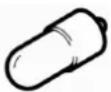 |
| Order no. | Description | |
| 6.288-094.0 | Battery terminal grease 50g | |
| 6.288-038.0 | Grease cartridge 400g | |
| 6.289-118.0 | Antifreeze for radiator 5 litres | |
| --- | Window washing water concentrate standard |
15.1 Fuses
- Mini
• Standard (Form C DIN 72581-3) - Maxi (SAE J1888)
| Order no. | Description | Fuse protection | Size |
| 7.644-028.0 | Blade-type fuse | 2 | Standard |
| 6,644-606.0 | Blade-type fuse | 5 | Mini |
| 6,644-607.0 | Blade-type fuse | 7.5 | Mini |
| 7.644-007.0 | Blade-type fuse | 7.5 | Standard |
| 6.644-608.0 | Blade-type fuse | 10 | Mini |
| 7.644-017.0 | Blade-type fuse | 10 | Standard |
| 6.644-609.0 | Blade-type fuse | 15 | Mini |
| 7.644-018.0 | Blade-type fuse | 15 | Standard |
| 7.644-005.0 | Blade-type fuse | 20 | Standard |
| 6.644-042.0 | Blade-type fuse | 30 | Mini |
| 7.644-040.0 | Blade-type fuse | 30 | Standard |
| 6.644-278.0 | Blade-type fuse | 30 | Maxi |
| 7.644-027.0 | Blade-type fuse | 40 | Standard |
| 6.644-246.0 | Blade-type fuse | 40 | Maxi |
| 9.667-909.0 | Blade-type fuse | 50 | Maxi |
16 Technical data
| MIC 70 | ||
| Internal combustion engine | ||
| Engine type Kubota V2403-CR-T-EW03 | Kubota V 2403-CR-EU1 | |
| Type Four-cylinder 4-stroke diesel | engine | |
| Engine capacity cm | ^3 | 2434 |
| Cooling type Water cooling | ||
| Engine performance kW 48,0 | ||
| Engine speed 1/min 2700 | ||
| Device performance data | ||
| Travel speed km/h 40 | ||
| Working speed (max.) km/h 20 | ||
| Climbing ability (max.) | % | 25 |
| Turning circle | m | 1,74 |
| Electrical system / battery | ||
| Battery type | - | Maintenance-free |
| Working voltage of the battery | V | 12 |
| Battery capacity | Ah | 80 |
| Dimensions and weights | ||
| Length | mm | 2.947 |
| Width | mm | 1.368 |
| Height | mm | 1.998 |
| Net weight (transport weight) | kg | 1650 |
| Approved total weight | kg | 3500 |
| Maximum permissible front axle load | kg | 2000 |
| Maximum permissible rear axle load | kg | 2000 |
| Trailer coupling vertical load | kg | 250 |
| Trailer load, inertia-braked | kg | 3000* * The maximum permissible to-tal weight with trailer must nev-er be exceeded |
| Unbraked trailer load | kg | 750* * The maximum permissible to-tal weight with trailer must nev-er be exceeded |
| Operating materials | ||
| Fuel type | Diesel | |
| Fuel tank capacity | 50 | |
| Engine oil type | SAE 10W-40 (CI-4, CH-4, CG-4, CF-4, CF) | |
| Engine oil volume | l | max. 9,5 |
| Type of coolant | Havoline XCL Antifreeze (SAEJ814C) | |
| Amount of coolant | l | 14 |
| Type of hydraulic oil | Renol B HV 46 (HVLP, Shell HF-E 46) | |
| Hydraulic oil quantity | l | 43 |
| Determined values in acc. with EN 60335-2-72 | ||
| Noise at the driver's ear according to Regulation (EU) 1322/2014, App. XIII | dB(A) | 75 |
Subject to technical modifications.
16.1 Tyres
The tyre pressures for various different axle loads and different speeds are listed in the following table.
| K500 (112, A8)26 x 12.00 - 12 | Axle load(1400 kg) | Axle load(1600 kg) | Axle load(1800 kg) | Axle load(2000 kg) |
| Speed 30 km/h 0.250 MPa 0.350 | 0 MPa 0.400 MPa 0.5 | 00 MPa | ||
| Speed 40 km/h 0.300 MPa 0.350 | 0 MPa 0.450 MPa 0.5 | 50 MPa |
| 195/75 R14 C205/65 R 16 C | Axle load(2000 kg) |
| 0.475MPa |
Contenu
Remarque
⑤Gyrophare, escamotable
①AUX 1+ (A - rouge)
②AUX 1- (B - rouge)
③AUX 2+ (A - bleu)
④AUX 2- (B - bleu)
⑤AUX 3+ (A - vert)
⑥AUX 3- (B - vert)
①Marteau d'urgence
①Joystick
①Point mort
①PTO Marche/Arrêt
Position 1 : Activer le PTO
natural_image
Close-up of a mechanical component with blue and green parts, labeled with number 1 (no text or symbols on the component itself)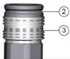
natural_image
Two identical diagrams showing a blue object being lifted by a red X, with no text or symbols present.natural_image
Front view of a vehicle chassis with labeled parts (no text or symbols beyond annotations)natural_image
Interior view of a mechanical or electronic device frame with a central component and mounting holes (no visible text or symbols)natural_image
Close-up of a joystick controller with colored buttons and a handle, labeled with number 1 (no text or symbols on the device itself)①Levier de commande
natural_image
Close-up of a mechanical assembly with numbered components, no visible text or symbolsnatural_image
Top-down view of a vehicle's rear front bumper with visible engine components and a numbered annotation (1) pointing to the side wheel.natural_image
Top-down view of a vehicle rear bumper with labeled parts (1 and 2), showing no text or symbols beyond labels.natural_image
Diagram of a tractor with labeled parts and structural connections (no readable text or symbols)natural_image
Close-up of a mechanical assembly with a pipe fitting and a red button, no visible text or symbolsnatural_image
Close-up of mechanical components with a numbered label pointing to a component (no readable text or symbols)
①Jauge d'huile
natural_image
Close-up of a mechanical device showing internal components with numbered labels (1 and 2), no readable text or symbols beyond labels.1
natural_image
Close-up of a mechanical component with an inset showing a close-up view of a circular component (no visible text or symbols)natural_image
Interior view of a car's seatbelt with labeled components and an inset showing a close-up of the seatbelt (no text or symbols visible)①Levier de blocage
②Cache
③Filtre à poussière
Remarque
| Fuse | Consumer | Fuse | Consumer | Fuse | Consumer |
| F015A | Right position lightsRight license plate lightBacklight multinstrument | F1415A | Extra controllerExtra CANSeat heating | F2510A | MAF sensorDisplayExtra brake |
| F025A | Left position lightsLeft license plate lightElectrical PTO front | F1510A | Power supply 3 | F2615A | H1 AC2 pumpSpeed selectionMode switchBrake pressure switchFNR switchReverse buzzerPark brakeFree wheel valveEngine air filterHydraulic oil filterHydraulic oil temp |
| F1615A | WiperWasher pumpHornDifferential lockDump valve | ||||
| F0310A | Fuse F01Fuse F02 | ||||
| F0415A | Hazard lightsInlenor light | ||||
| F0530A | Heated windshieldHealed mirrors | F1730A | Float valvesPTO valvesWeight transfer valvesFrontloader lock valve | ||
| F0620A | Electrical PTO frontElectrical PTO rear | ||||
| F0715A | Power supply 1 | F1820A | Air condition | F2710A | Ignition |
| F0830A | Seat compressorStop solenoid pull | F195A | EGR valveEngine diagnostic connector | F285A | Ignition |
| F0920A | Low beamHigh beamSwitch high/low roadlights | F2010A | Cabin 12V socket frontCabin 12V socket rear | F2925A | Engine ECUEngine sensorsFuel pump |
| F2115A | Rocker switch lightsElectrical change valvesFrontloader change valveLoad damping valvesRadio | F3040A | Preheat | ||
| F1030A | Worklights frontWorklights rearRotating beacon | ||||
| F1120A | Change valve rearLeak valveLeak valve load platform | F2210A | Control module | F3110A | Diagnostic connectorDisplay |
| F322A | Radio constant feed | ||||
| F1210A | Power supply 2 | F2310A | Cruise controlBrake lightsReverse pressure switch | F335A | Start indication |
| F1315A | Direction lightsMulti instrumentSpeed indicatorSpeedometer | F3450A | Starter | ||
| F247.5A | AlternatorSeat switchFuel pumpRear view camera |
①Levier de blocage
②Cache
natural_image
Interior view of an electronic device showing a green circuit board with multiple components and wiring (no visible text or symbols)①Fusibles
natural_image
Interior view of a car engine bay with visible hoses, springs, and internal components (no text or symbols)- Appuyer sur
.
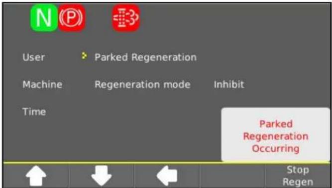
Nota
①AUX 1+ (A - rosso)
②AUX 1- (B - rosso)
③AUX 2+ (A - blu)
④AUX 2- (B - blu)
⑤AUX 3+ (A - verde)
⑥AUX 3- (B - verde)
①PTO elettrico
natural_image
Close-up of a car's side panel with mesh pattern and three numbered annotations (1, 2, 3) pointing to internal components.①Acceleratore
②Pedale del freno
①Volante
②Tergicristallo
①Joystick
①PTO on/off
natural_image
Close-up of a car's front suspension system with attached lock and valve (no visible text or symbols)①
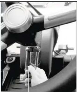
natural_image
Close-up of a hand using a tool to adjust or install a component, no visible text or symbols2
8.2.4 Pedale inching
natural_image
Front view of a vehicle's rear suspension system with labeled components (no text or symbols beyond labels)natural_image
Close-up of a mechanical component with a central recessed part and mounting holes, no visible text or symbols.natural_image
Close-up of a black handheld device with a control knob and indicator lights, labeled with number 1 (no text or symbols on the device itself)①Leva di comando
natural_image
Close-up of a mechanical assembly with labeled parts (1 and 2), no readable text or symbols beyond labels①Puntelli anteriori
natural_image
Top-down view of a vehicle rear bumper with visible engine components and a numbered annotation (1) pointing to the front wheel.natural_image
Top-down view of a vehicle's rear front bumper with labeled parts (1 and 2), showing no text or symbols beyond labels.natural_image
Front view of a tractor with attached equipment and numbered components (no visible text or symbols)natural_image
Close-up of a mechanical assembly with a metallic tool inserted, showing no visible text or symbols.natural_image
Close-up of mechanical components with a numbered label pointing to a component (no readable text or symbols)natural_image
Close-up of a mechanical assembly with labeled parts (① and ②), showing components like bolts, wires, and a central component (no text or symbols beyond labels)①Vite serbatoio carburante
natural_image
Close-up of a mechanical assembly with an inset showing a component being inserted into a housing (no visible text or symbols)①Coperchio
①Leva di bloccaggio
②Coperchio
| Fuse | Consumer | Fuse | Consumer | Fuse | Consumer |
| F015A | Right position lightsRight license plate lightBacklight multinstrument | F1415A | Extra controllerExtra CANSeat heating | F2510A | MAF sensorDisplayExtra brake |
| F025A | Left position lightsLeft license plate lightElectrical PTO front | F1510A | Power supply 3 | F2615A | H1 AC2 pumpSpeed selectionMode switchBrake pressure switchFNR switchReverse buzzerPark brokeFree wheel valveEngine air filterHydraulic oil fillerHydraulic oil temp |
| F1615A | WiperWasher pumpHomDifferential lockDump valve | ||||
| F0310A | Fuse F01Fuse F02 | ||||
| F0415A | Hazard lightsIntenor light | ||||
| F0530A | Heated windshieldHeated mirrors | F1730A | Float valvesPTO valvesWeight transfer valvesFrontloader lock valve | ||
| F0820A | Electrical PTO frontElectrical PTO rear | ||||
| F0715A | Power supply 1 | F1820A | Air condition | F2710A | Ignition |
| F0830A | Seat compressorStop solenoid pull | F195A | EGR valveEngine diagnostic connector | F285A | Ignition |
| F0920A | Low beamHigh beamSwitch high/low roadlights | F2010A | Cabin 12V socket frontCabin 12V socket rear | F2925A | Engine ECUEngine sensorsFuel pump |
| F2115A | Rocker switch lightsElectrical change valvesFrontloader change valveLoad damping valvesRadio | F3040A | Preheat | ||
| F1030A | Worklights frontWorklights rearRotating beacon | ||||
| F3110A | Diagnostic connectorDisplay | ||||
| F1120A | Change valve rearLeak valveLeak valve load platform | F2210A | Control module | F322A | Radio constant feed |
| F1210A | Power supply 2 | F2310A | Cruise controlBrake lightsReverse pressure switch | F335A | Start indication |
| F1315A | Direction lightsMulti instrumentSpeed indicatorSpeedometer | F247.5A | AlternatorSeat switchFuel pumpRear view camera | F3450A | Starter |
natural_image
Interior view of an electronic circuit board with visible components and wiring (no text or symbols)①Fusibili
natural_image
Interior view of a vehicle engine bay with visible hoses, springs, and internal components (no text or symbols)- Premere
.

Nota
①Interruptor principal
①AUX 1+ (A - rojo)
②AUX 1- (B - rojo)
③AUX 2+ (A - azul)
④AUX 2- (B - azul)
⑤AUX 3+ (A - verde)
⑥AUX 3- (B - verde)
①PTO eléctrico
6.5 Interruptor principal

①Interruptor principal
6.6 Cabina del conductor
①Volante
②Limpiaparabrisas
①Joystick
①Posición neutra
①Interruptor principal
①Reposacabezas
① Reposacabezas
flowchart
graph TD
    A["Stage 1: Rabbit"] --> B["Stage 2: Turtle"]
    B --> C["Stage 3: Gear Icon"]
    C --> D["Stage 4: Snake Icon"]
①MODO DE TRANSPORTE RÁPIDO
natural_image
Front view of a vehicle chassis with labeled parts (no text or symbols beyond annotations)①Alojamientos
natural_image
Close-up of a mechanical component with a metallic housing and mounting holes, labeled with number 1 (no text or symbols on the main structure)natural_image
Close-up of a game controller with blue, red, and green indicator lights (no text or symbols visible)①Palanca de mando
natural_image
Top-down view of a vehicle's rear front bumper with visible headlights, buttons, and structural components (no text or symbols)①Alojamientos
natural_image
Top-down view of a vehicle rear bumper with labeled parts (1 and 2), showing no visible text or symbols beyond labels.natural_image
Side view of a tractor with visible structural components and numbered parts (no text or symbols)natural_image
Close-up of a mechanical assembly with a metal component inserted, showing no visible text or symbols.①Cilindros de frenos hidráulicos
natural_image
Close-up of a mechanical component with a numbered annotation pointing to a specific part (no visible text or symbols)
①Cierre de cubierta lateral
② Cubierta lateral
natural_image
Close-up of a mechanical device showing two labeled parts (① and ②) with no visible text or symbols on the main components.natural_image
Close-up of a mechanical component with an inset showing a close-up view of a component (no visible text or symbols)①Tornillo de mariposa
① Cubierta
②Filtro de polvo
Nota
| Fuse | Consumer | Fuse | Consumer | Fuse | Consumer |
| F015A | Right position lightsRight license plate lightBacklight mult instrument | F1415A | Extra controllerExtra CANSeat heating | F2510A | MAF sensorDisplayExtra brake |
| F025A | Left position lightsLeft license plate lightElectrical PTO front | F1510A | Power supply 3 | F2615A | H1 AC2 pumpSpeed selectionMode switchBrake pressure switchFNR switchReverse buzzerPark brakeFree wheel valveEngine air filterHydraulic oil filterHydraulic oil temp. |
| F0310A | Fuse F01Fuse F02 | ||||
| F0415A | Hazard lightsInferior light | F1615A | WiperWasher pumpHornDifferential lockDump valve | ||
| F0530A | Heated windshieldHeated mirrors | F1730A | Float valvesPTO valvesWeight transfer valvesFrontloader lock valve | ||
| F0620A | Electrical PTO frontElectrical PTO rear | ||||
| F0715A | Power supply 1 | F1820A | Air condition | F2710A | Ignition |
| F0830A | Seat compressorStop solenoid pull | F195A | EGR valveEngine diagnostic connector | F285A | Ignition |
| F0920A | Low beamHigh beamSwitch high/low roadlights | F2010A | Cabin 12V socket frontCabin 12V socket rear | F2925A | Engine ECUEngine sensorsFuel pump |
| F1030A | Worklights frontWorklights rearRotating beacon | F2115A | Rocker switch lightsElectrical change valvesFrontloader change valveLoad damping valvesRadio | F3040A | Preheat |
| F1120A | Change valve rearLeak valveLeak valve load platform | F2210A | Control module | F3110A | Diagnostic connectorDisplay |
| F1210A | Power supply 2 | F2310A | Cruise controlBrake lightsReverse pressure switch | F322A | Radio constant feed |
| F1315A | Direction lightsMulti instrumentSpeed indicatorSpeedometer | F247.5A | AlternatorSeat switchFuel pumpRear view camera | F335A | Start indication |
| F3450A | Starter |
①Fusibles
natural_image
Interior view of a vehicle engine bay with visible internal components and wiring (no text or symbols)- Pulse
.

Aviso
①Interruptor principal
②Bateria desligada
③Bateria ligada
6.5 Interruptor principal
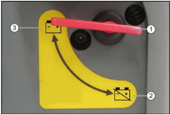
①Interruptor principal
②Bateria desligada
③Bateria ligada
①Pedal do acelerador
②Pedal do travão
①Volante
①Joystick
①Ligar/desligar o PTO
①Interruptor principal
②Bateria desligada
③Bateria ligada
①Apoio da cabeça
①Apoio da cabeça
①Pedal do acelerador
②Pedal do travão
8.2.3 Pedal do travão MIC 70
①Suporte de 3 pontos
②Guidão inferior
natural_image
Front view of a vehicle chassis with labeled parts (no text or symbols beyond annotations)natural_image
Close-up of a mechanical component with a metallic housing and mounting holes, no visible text or symbolsnatural_image
Close-up of a joystick controller with colored buttons and a handle, labeled with number 1 (no text or symbols on the device itself)①Alavanca de comando
①Parafuso com porca
natural_image
Close-up of a mechanical assembly with numbered components, no visible text or symbolsnatural_image
Top-down view of a vehicle's rear back showing engine components and a numbered annotation (1), no readable text or symbols present.natural_image
Top-down view of a vehicle rear bumper with labeled parts (1, 2), showing no visible text or symbols beyond labels.natural_image
Close-up of a mechanical assembly with a metallic component and a numbered label (1), no readable text or symbols present.10.2.3 Abrir as válvulas de bypass
natural_image
Close-up of mechanical components with a numbered label pointing to a component (no readable text or symbols)①Válvula bypass
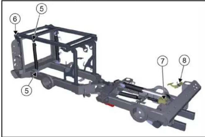
12.7.8 Mudar as rodas
⚠PERIGO
natural_image
Close-up of a mechanical device showing internal components with numbered labels (1 and 2), no readable text or symbols beyond labels.①Tampa de enchimento de óleo
- Retirar a tampa de enchimento de óleo.
- Reabastecer óleo de motor.
natural_image
Close-up of a mechanical component with an inset showing a close-up of a component (no visible text or symbols)①Cobertura da tampa do radiador
②Tampa do radiador
①Cobertura
②Filtro de pó
Aviso
①Banco do condutor
②Filtro de pó
③Alavanca de ar ambiente
- Deslocar o banco do condutor completamente para a frente.
- Retirar o filtro de pó.
- Substituir o filtro de pó.
- Empurrar o banco do condutor para trás.
12.8 Limpeza
△CUIDADO
Perigo de ferimentos e danos
| Fuse | Consumer | Fuse | Consumer | Fuse | Consumer |
| F015A | Right position lightsRight license plate lightBacklight multinstrument | F1415A | Extra controllerExtra CANSeat heating | F2510A | MAF sensorDisplayExtra brake |
| F025A | Left position lightsLeft license plate lightElectrical PTO front | F1510A | Power supply 3 | F2615A | H1 AC2 pumpSpeed selectionMode switchBrake pressure switchFNR switchReverse buzzerPark brakeFree wheel valveEngine air filterHydraulic oil filterHydraulic oil temp |
| F1615A | WiperWasher pumpHornDifferential lockDump valve | ||||
| F0310A | Fuse F01Fuse F02 | ||||
| F0415A | Hazard lightsInferior light | ||||
| F0530A | Heated windshieldHeated mirrors | F1730A | FootvalvesPTO valvesWeight transfer valvesFrontloader lock valve | ||
| F0620A | Electrical PTO frontElectrical PTO rear | ||||
| F0715A | Power supply 1 | F1820A | Air condition | F2710A | Ignition |
| F0830A | Seat compressorStop solenoid pull | F195A | EGR valveEngine diagnostic connector | F285A | Ignition |
| F0920A | Low beamHigh beamSwitch high/low roadlights | F2010A | Cabin 12V socket frontCabin 12V socket rear | F2925A | Engine ECUEngine sensorsFuel pump |
| F2115A | Rocker switch lightsElectrical change valvesFrontloader change valveLoad damping valvesRadio | F3040A | Preheat | ||
| F1030A | Worklights frontWorklights rearRotating beacon | ||||
| F1120A | Change valve rearLeak valveLeak valve load platform | F2210A | Control module | F3110A | Diagnostic connectorDisplay |
| F1210A | Power supply 2 | F2310A | Cruise controlBrake lightsReverse pressure switch | F322A | Radio constant feed |
| F1315A | Direction lightsMulti instrumentSpeed indicatorSpeedometer | F247.5A | AlternatorSeat switchFuel pumpRear view camera | F335A | Start indication |
| F3450A | Starter |
①Maneta
②Cobertura
①Fusíveis
natural_image
Interior view of a vehicle engine bay with visible hoses, springs, and internal components (no text or symbols)- Premir
.
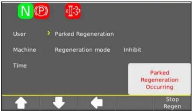
Instructie
①AUX 1+ (A - rood)
②AUX 1- (B - rood)
③AUX 2+ (A - blauw)
④AUX 2- (B - blauw)
⑤AUX 3+ (A - groen)
⑥AUX 3- (B - groen)
①Hoofdschakelaar
②Accu gescheiden
③Accu verbonden
①Noodhamer
natural_image
Close-up of a car's side panel showing a mesh grille and circular object, with three numbered annotations (1, 2, 3) pointing to specific regions.①Differentieelgrendel
②Groot licht
③Verontreiniging motorluchtfilter
④Niet bezet
⑤Rijlicht (dimlicht)
⑥Knipperlicht
6.7 Multifunctionele indicatie/display MIC 70
①Rijpedaal
②Rempedaal
③Pedaal hellingsverstelling stuurwiel
④Inchpedaal
⑤Reservoir remvloeistof
6.8.1 Rijpedaal
LET OP
①Stuurwiel
②Ruitenwisser
Stand J: intervalschakeling
Stand 0: uit
Stand I: normaal
Stand II: snel
①PTO aan/uit
Stand 1: PTO inschakelen
①Hoofdsteun
②Documentenvak
③Instelling lendenwervelsteun
④Hellingsinstelling rugleuning
①Hoofdsteun
②Documentenvak
③Instelling lendenwervelsteun
④Hellingsinstelling rugleuning
①Pedaal hellingsverstelling stuurwiel
②Klemhendel hoogteverstelling stuurwiel
①Rijpedaal
②Rempedaal
③Pedaal hellingsverstelling stuurwiel
④Inchpedaal
⑤Reservoir remvloeistof
8.2.1 Rijpedaal
LET OP
①Koppelingsstekker
②Koppelingsmof
③Ring
natural_image
Top-down view of a vehicle chassis with labeled components (no text or symbols beyond numbered annotations)natural_image
Interior view of a mechanical or electronic device frame with a central component and mounting holes (no visible text or symbols)natural_image
Close-up of a joystick controller with colored buttons and adjustment knob (no text or symbols visible)①Borgbout (2x)
②Borgklem (2x)
natural_image
Top-down view of a vehicle rear bumper with visible headlights, buttons, and structural components (no text or symbols)①Opnameframe
natural_image
Top-down view of a vehicle rear bumper with labeled parts (1 and 2), showing no visible text or symbols beyond labels.①Aanhangerkoppeling
natural_image
Front view of a tractor with visible structural components and numbered parts (no text or symbols)natural_image
Close-up of a mechanical assembly with a metallic component and a numbered label (1), no readable text or symbols present.natural_image
Close-up of mechanical components with a numbered label pointing to a component (no readable text or symbols)①Bypassventiel
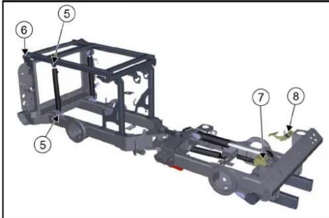
①Oliepeilstok
natural_image
Close-up of a mechanical device showing internal components and wiring (no text or symbols visible)①Schroef brandstoftank
①Indicatie hydraulisch oliepeil
②Maximaal peil hydraulische olie
③Minimaal peil hydraulische olie
natural_image
Close-up of a mechanical device with an inset showing a close-up of a component (no visible text or symbols)①Afdekking radiateurdeksel
②Radiateurdeksel
①Afdekking
②Stoffilter
Instructie
①Klemhendel
②Afdekking
③Stoffilter
Instructie
①Bestuurdersstoel
②Stoffilter
| Fuse | Consumer | Fuse | Consumer | Fuse | Consumer |
| F015A | Right position lightsRight license plate lightBacklight multinstrument | F1415A | Extra controllerExtra CANSeat heating | F2510A | MAF sensorDisplayExtra brake |
| F025A | Left position lightsLeft license plate lightElectrical PTO front | F1510A | Power supply 3 | F2615A | H1 AC2 pumpSpeed selectionMode switchBrake pressure switchFNR switchReverse buzzerPark brakeFree wheel valveEngine air filterHydraulic oil filterHydraulic oil temp. |
| F1615A | WiperWasher pumpHornDifferential lockDump valve | ||||
| F0310A | Fuse F01Fuse F02 | ||||
| F0415A | Hazard lightsInterior light | ||||
| F0530A | Heated windshieldHeated mirrors | F1730A | Float valvesPTO valvesWeight transfer valvesFrontloader lock valve | ||
| F0620A | Electrical PTO frontElectrical PTO rear | ||||
| F0715A | Power supply 1 | F1820A | Air condition | F2710A | Ignition |
| F0830A | Seat compressorStop solenoid pull | F195A | EGR valveEngine diagnostic connector | F285A | Ignition |
| F0920A | Low beamHigh beamSwitch high/low roadlights | F2010A | Cabin 12V socket frontCabin 12V socket rear | F2925A | Engine ECUEngine sensorsFuel pump |
| F2115A | Rocker switch lightsElectrical change valvesFrontloader change valveLoad damping valvesRadio | ||||
| F1030A | Worklights frontWorklights rearRotating beacon | F3040A | Preheat | ||
| F3110A | Diagnostic connectorDisplay | ||||
| F1120A | Change valve rearLeak valveLeak valve load platform | F2210A | Control module | F322A | Radio constant feed |
| F1210A | Power supply 2 | F2310A | Cruise controlBrake lightsReverse pressure switch | F335A | Start indication |
| F1315A | Direction lightsMulti instrumentSpeed indicatorSpeedometer | F247.5A | AlternatorSeat switchFuel pumpRear view camera | F3450A | Starter |
①Klemhendel
②Afdekking
①Zekeringen
②Zekeringtester met groene led
Instructie
natural_image
Interior view of a vehicle engine bay with visible hoses, springs, and components (no text or symbols)- Op
drukken.
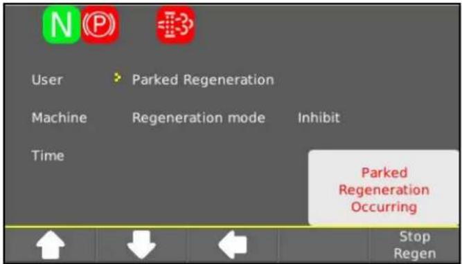
16.1 Bandenuitrusting
Υπόδειξη
① Γενικός διακόπτης
①Γενικός διακόπτης
natural_image
Close-up of a car's front light fixture showing mesh pattern and labeled components (no text or symbols beyond labels)①Πεντάλ γκαζιού
②Πεντάλ φρένου
①Τιμόνι
①Δυναμοδότης On/Off
①Διακόπτης Tempomat
natural_image
Top-down view of a vehicle chassis with labeled components (no text or symbols beyond annotations)①Πλαίσιο υποδοχής
natural_image
Close-up of a metallic electronic device casing with a central component and mounting holes (no visible text or symbols)natural_image
Close-up of a game controller with blue, red, and green buttons and a black handle (no text or symbols visible)①Μοχλός χειρισμού
natural_image
Close-up of a mechanical assembly with numbered components, no visible text or symbolsnatural_image
Top-down view of a vehicle's rear front bumper with visible engine components and a numbered annotation (1) pointing to the side.①Πλαίσιο υποδοχής
natural_image
Top-down view of a vehicle rear bumper with labeled parts (1 and 2), showing engine, dashboard, and wheel assembly (no text or symbols beyond labels)①Κοτσαδόρος
natural_image
Front view of a tractor with visible frame and side-mounted equipment, surrounded by control panels (no text or symbols)natural_image
Close-up of a mechanical assembly with a metal rod inserted, showing no visible text or symbols.natural_image
Close-up of a mechanical component with a labeled part (1) and no visible text or symbols①Βαλβίδα παράκαμψης
① Παξιμάδια τροχού
②Τροχός
natural_image
Close-up of a mechanical device showing internal components with numbered labels (1 and 2), no readable text or symbols beyond labels.①Ρακόρ μακρύ
natural_image
Close-up of a mechanical assembly with an inset showing a component inserted into a housing (no visible text or symbols)①Κάλυμμα
| Fuse | Consumer | Fuse | Consumer | Fuse | Consumer |
| F015A | Right position lightsRight license plate lightBacklight multinstrument | F1415A | Extra controllerExtra CANSeat heating | F2510A | MAF sensorDisplayExtra brake |
| F025A | Left position lightsLeft license plate lightElectrical PTO front | F1510A | Power supply 3 | F2615A | H1 AC2 pumpSpeed selectionMode switchBrake pressure switchFNR switchReverse buzzerPark brake |
| F1615A | WiperWasher pumpHornDifferential lockDump valve | ||||
| F0310A | Fuse F01Fuse F02 | ||||
| F0415A | Hazard lightsInferior light | ||||
| F0530A | Heated windshieldHeated mirrors | F1730A | Float valvesPTO valvesWeight transfer valvesFrontloader lock valve | Free wheel valveEngine air filterHydraulic oil filterHydraulic oil temp | |
| F0620A | Electrical PTO frontElectrical PTO rear | ||||
| F0715A | Power supply 1 | F1820A | Air condition | F2710A | Ignition |
| F0830A | Seat compressorStop solenoid pull | F195A | EGR valveEngine diagnostic connector | F285A | Ignition |
| F0920A | Low beamHigh beamSwitch high/low roadlights | F2010A | Cabin 12V socket frontCabin 12V socket rear | F2925A | Engine ECUEngine sensorsFuel pump |
| F2115A | Rocker switch lightsElectrical change valvesFrontloader change valveLoad damping valvesRadio | F3040A | Preheat | ||
| F1030A | Worklights frontWorklights rearRotating beacon | F3110A | Diagnostic connectorDisplay | ||
| F1120A | Change valve rearLeak valveLeak valve load platform | F2210A | Control module | F322A | Radio constant feed |
| F1210A | Power supply 2 | F2310A | Cruise controlBrake lightsReverse pressure switch | F335A | Start indication |
| F1315A | Direction lightsMulti instrumentSpeed indicatorSpeedometer | F247.5A | AlternatorSeat switchFuel pumpRear view camera | F3450A | Slarter |
①Μοχλός σύσφιξης
②Κάλυμμα
natural_image
Interior view of a vehicle engine bay with visible internal components and wiring (no text or symbols)- Πατήστε
.

natural_image
Black silhouette of a hand giving a thumbs-up gesture (no text or symbols)THANK YOU!
MERCI! DANKE! iGRACIAS!
Registrieren Sie Ihr Produkt und profitieren Sie von vielen Vorteilen. Register your product and benefit from many advantages. Enregistrez votre produit et bénéficier de nombreux avantages. Registre su producto y aproveche de muchas ventajas.
www.kaercher.com/welcome

Bewerten Sie Ihr Produkt und sagen Sie uns Ihre Meinung. Rate your product and tell us your opinion. Évaluer votre produit et dites-nous votre opinion. Reseñe su producto y díganos su opinión.

natural_image
Icon showing a gear and wrench, no text or symbols presentwww.kaercher.com/dealersearch
Alfred Kärcher SE & Co. KG
Alfred-Kärcher-Str. 28-40
71364 Winnenden (Germany)
Tel.: +49 7195 14-0
Fax: +49 7195 14-2212