MIC 26C Advanced Comfort - Tractor Kärcher - Free user manual and instructions
Find the device manual for free MIC 26C Advanced Comfort Kärcher in PDF.

User questions about MIC 26C Advanced Comfort Kärcher
0 question about this device. Answer the ones you know or ask your own.
Ask a new question about this device
Download the instructions for your Tractor in PDF format for free! Find your manual MIC 26C Advanced Comfort - Kärcher and take your electronic device back in hand. On this page are published all the documents necessary for the use of your device. MIC 26C Advanced Comfort by Kärcher.
USER MANUAL MIC 26C Advanced Comfort Kärcher
$$ F = \text {v o l l} $$
$$ E = \text {l e e r} $$
2 Information about the vehicle 2
2.1 Proper use 2
2.2 Centre of Gravity 2
3 General notes 2
3.1 Environmental protection, REACH and disposal of the worn out vehicle 2
3.2 Warranty 3
3.3 Accessories, spare parts, upgrade kits 3
3.4 Symbols in the operating instructions 3
3.5 Symbols on the machine 3
4 Safety instructions 3
4.1 General notes on safety 3
4.2 Work clothing 3
4.3 Unloading tips 4
4.4 Safety instructions concerning the operation 4
4.5 Safety information concerning the driving operation 4
4.6 Safety information concerning the combustion engine 5
4.7 Safety information concerning the transport of the appliance 5
4.8 Safety information concerning maintenance and care 5
4.9 Safety Devices 5
5 Control elements
5.1 Device with protective bar 6
5.2 Device with driver cabin 6
5.3 Steering column 7
5.4 Multi-functional lifter for lights, indicators and horn 7
5.5 Pedals 7
5.6 Lowering speed control valve (option) 8
5.7 Connections 8
5.8 Console (for device with driver cabin) 10
5.9 Joystick function (for device with driver cabin) 11
5.10 Console (for device with protective bar) 12
5.11 Operating lever function (for device with protective bar) 13
6 Before Startup
6.1 Prior to initial start-up 14
6.2 Refuelling 14
6.3 Fill the windshield wiper system 14
6.4 Adjusting driver's seat 14
6.5 Set the steering wheel position 15
6.6 Prior to start/safety test 15
6.7 Daily maintenance tasks 15
7 Operation
7.1 Driving 15
7.2 Turn off device 16
7.3 Frost protection 16
7.4 Transport 16
8 Attachment sets
8.1 Operations 17
8.2 Mower 125 cm 17
8.3 Mower 135 cm 17
8.4 Front brush roller 18
8.5 Snow removal shields 18
8.6 Snow blower 18
8.7 Caster 19
8.8 Chassis mounted spreader 20
8.9 Balance weight without attachment hitch 21
8.10 Balance weight with attachment hitch 21
8.11 Towing hitch 22
8.12 Coupling triangle 22
8.13 Weedbroom 22
9 Storage 24
10 Care and maintenance 25
10.1 General notes 25
10.2 Panels 25
10.3 Cleaning 26
10.4 Maintenance intervals 26
10.5 Maintenance Works 27
10.6 Fuses 33
11 Troubleshooting 34
11.1 Faults with display 34
11.2 Faults without display 34
11.3 Towing 34
12 Technical specifications 35
12.1 Tyres 36

Please read and comply with these original operating instructions prior to the initial operation of your vehicle and store them for later use or subsequent owners.
2 Information about the vehicle
2.1 Proper use
Use this appliance only as directed in these operating instructions.
This machine (attachment carrier) was developed for use on greens, to take care of landscaping and for winter services.
- The MIC 26C device is available as a version with a driver cabin and as a version with a protective bar. The protective bar can be folded down, e.g. when mowing under trees.
For safety reasons (flying stones, dust, etc. during sweeping), the device with protective bar is not permitted for work with the sweeping system. - The appliance may only be operated on public roads if it is equipped with the upgrade kit StVZO (optional ex works).
- Different attachments (not included in the scope of delivery) can be connected to the front or the back of this machine. Attachments that may jeopardise the safety or stability of the machine, must not be used.
-IMPORTANT! Before connecting attachments that were not specifically intended for this machine, please contact your dealer to check how these attachments should be connected and used. This is essential for the safety of the driver and the machine as well as for possible warranty claims. - This machine (attachment carrier) is ready to operate when delivered. Proper treatment and maintenance increase the operational safety and product life of the machine.
- The machine can also be used as a towing vehicle (hitch is optionally available).
- The appliance should not be used in closed rooms.
- The following applies in general: Keep highly-flammable substances away from the appliance (danger of explosion/fire).
-
If not attachment is connected to the rear of the appliance, you must install the balance weights on the rear.
-
The machine may only be operated on the surfaces approved by the company or its authorised representatives.
2.1.1 Foreseeable misuse
Any use other than the one intended and described above is prohibited. The user is liable for any hazards arising from incorrect use.
The use for any other purposes than described in these instructions is prohibited.
Transporting persons on the vehicle, the load bed or attachments is not permitted.
No changes must be performed on the vehicle.
The machine may not be used or stored in hazardous areas. It is not allowed to use the appliance in hazardous locations.
2.2 Centre of Gravity
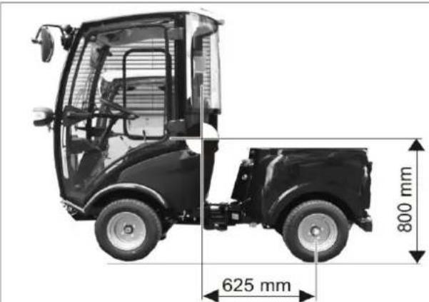
Position of centre of gravity without attachments installed.
Rear attachments and load statuses have an impact on the vehicle's centre of gravity and thus on the driving characteristics.
If not attachment is connected to the rear of the appliance, you must install the balance weights on the rear.
3 General notes
Your sales outlet should be informed about any transit damage noted when unpacking the product.
- Read and adhere to the operating instructions and safety notes of the attachments affixed to the appliance.
- Warning and information plates on the machine provide important directions for safe operation.
- In addition to the information contained in the operating instructions, all statutory safety and accident prevention regulations must be observed.
- In these operating instructions, the terms device, appliance carrier, machine and vehicle are used synonymously.
3.1 Environmental protection, REACH and disposal of the worn out vehicle
3.1.1 Environmental protection

The packaging material can be recycled. Please do not throw the packaging material into household waste; please send it for recycling.

Batteries, oil, fuels and similar substances must not be released into the environment. Please dispose of these substances via suitable collection systems.
3.1.2 Ingredients (REACH)
The latest information on ingredients can be found under: www.kaercher.de/REACH
3.1.3 Disposal of the worn out vehicle
Worn out vehicles contain valuable recyclable materials that should be recycled properly. We recommend to cooperate with a waste management company for the disposal of your vehicle.
3.2 Warranty
The warranty terms published by our competent sales company are applicable in each country. We will repair potential failures of your accessory within the warranty period free of charge, provided that such failure is caused by faulty material or defects in fabrication. In the event of a warranty claim please contact your dealer or the nearest authorized Customer Service center. Please submit the proof of purchase.
3.3 Accessories, spare parts, upgrade kits
Only accessories, spare parts and upgrade kits that are approved by the manufacturer may be used.
To avoid risks, all repairs and replacement of spare parts may only be carried out by the authorised customer service personnel.
For additional information about spare parts, please go to the Service section at www.kaercher.com.
3.4 Symbols in the operating instructions
△DANGER
Warns about immediate danger which can lead to severe injuries or death.
△WARNING
Warns about possible danger which could lead to severe injuries or death.
CAUTION
Points out a possibly dangerous situation which can lead to light injuries or property damage.
ATTENTION
Pointer to a possibly dangerous situation, which can lead to property damage.
3.5 Symbols on the machine

CAUTION
Risk of burns on account of hot surfaces! Allow the exhaust to cool down sufficiently before starting work on the machine.

CAUTION
Risk of burns on account of hot hydraulic quick couplers! Wear gloves while separating the couplings.

DANGER
Danger of crushing. Make sure that no persons are present near the arm hinges.

WARNING
Danger of crushing. Keep hands off the marked location.


CAUTION
Risk of damage. Do not enter.

△DANGER
Danger of tipping. Only drive on terrain with a max. of 10% incline.

Fill in coolant here.
4 Safety instructions
4.1 General notes on safety 4.2 Work clothing
- The machine with working equipment must be checked to ensure that it is in proper working order and is operating safely prior to use. Otherwise, the appliance must not be used.
-
If the appliance is used in hazardous areas (e.g. filling stations) the corresponding safety provisions must be observed. It is not allowed to use the appliance in hazardous locations.
-
Always use appropriate gloves while working on the device.
- Ensure that the operator wears tight-fitting clothes. Wear safety shoes and avoid loose clothing.
- Wear suitable headgear so that braids or long hair cannot get caught in rotating parts.
- Do not wear jewellery, rings or the like during work.
4.3 Unloading tips
△DANGER
Risk of injury, risk of damage! Observe the weight of the appliance when you load it!
Unladen weight (without attachment sets) $70 - 944 kg *
- If upgrade kits are installed, the weight is respectively higher.
△DANGER
The vehicle is not approved for crane loading.
Do not use a fork lift, the appliance could get damaged.
4.4 Safety instructions concerning the operation
- The operator must use the appliance properly. The person must consider the local conditions and must pay attention to third parties, in particular children, when working with the appliance.
- Never leave the machine unattended so long as the engine is running. The operator may leave the appliance only when the engine has come to a standstill, the appliance has been protected against accidental movement, if necessary, by applying the immobilization brake and the ignition key has been removed.
- The appliance may only be used by persons who have been instructed in handling the appliance or have proven qualification and expertise in operating the appliance or have been explicitly assigned the task of handling the appliance.
- The appliance must not be operated by children or persons who have not been instructed accordingly.
- The appliance may be used by individuals with limited physical, sensory or cognitive abilities or lack of experience and knowledge if they are under supervision or were instructed regarding the safe use of the appliance and understand the resulting risks.
- Children should be supervised to prevent them from playing with the appliance.
- Do not open the hood when the motor is running.
4.5 Safety information concerning the driving operation
It is important to follow all safety instructions, rules and regulations applicable for driving motor vehicles.
- The appliance must not be operated by children, young persons or persons who have not been instructed accordingly.
- It is strictly prohibited to take co-passengers.
- Please remove the ignition key, when not in use, to avoid unauthorised use of the appliance.
- Danger of accident by reduced brake performance. Do not lay a foot mat into the driver cabin. Keep loose objects that may slip under the accelerator out of the driver cabin.
△DANGER
Risk of injury!
Prior to each use, the safety check described in the Chapter "Startup" must be conducted.
- All operating levers and switches must be in neutral prior to starting the motor. The driver must be seated when the motor is started. The drive pedal must not be pressed during the starting process.
- Fasten seat belt during driving and the performance of work.
- The vehicle may only be started while sitting in the seat.
- During transports, the front attachment frame can be lifted all the way up and locked; for this, pull the lever all the way up.
- Be especially careful when working on slopes and ditches.
△DANGER
Danger of tipping!
The steering characteristics of a vehicle with articulated steering differ considerably from those of a passenger car.
The falling and rising gradients in the direction of travel may not exceed 25% .
Avoid abrupt steering movements.
Drive slowly when cornering.
Danger of tipping on unstable ground.
Danger of tipping with excessive sideways tilt. Danger of tipping. Only drive on terrain with a max. of 10% incline.
When driving in mountains or valleys and driving laterally to slopes, avoid driving suddenly around bends.
Adjust travel speed to the ambient conditions and the load status when driving straight on and when driving around bends.
Beware that the braking properties are different depending on whether the vehicle is being operated in drive mode or transport mode!
4.5.1 Tyres and tyre pressure
- Check the pressure reducer on the compressor for the correct setting before correcting the tire pressure.
- Do not exceed maximum tyre pressure. The permissible tyre pressure must be read on the tyre or on the rim. If there are different values, use the lower one.
- Tyres and recommended tyre pressures are listed in the chapter "Technical Data | Tyres". In addition, there is a label with the recommended tyre pressures in the driver cabin.
4.6 Safety information concerning the combustion engine
- Read the operating instructions of the engine manufacturer before start-up and follow the safety instructions carefully.
△DANGER
Risk of injury!
- Do not close the exhaust.
- Do not bend over the exhaust or touch it (risk of burns).
- Do not touch the combustion engine (risk of burns).
- Risk of burns Let the appliance cool off before removing the covers.
- Danger of burns! Never open the lid on the cooler while the motor has operating temperature. The container is under pressure.
- Exhaust gases are poisonous and hazardous to health, do not inhale them.
- The engine requires approx. 5 seconds to come to a standstill once it has been switched off. During this time, stay well clear of the working area.
- Risk of injury due to unprotected fan wheel.
- Only use the fuels specified in the operating instructions. Risk of explosion due to the use of inappropriate fuels. Refer to Chapter "Technical data".
- When refuelling, ensure that no fuel reaches hot surfaces.
- Ensure that there is adequate ventilation or provision for diverting the exhaust gas while operating the appliance in closed rooms (risk of poisoning).
4.7 Safety information concerning the transport of the appliance
The engine is to be brought to a standstill and the appliance is to be fastened properly during transportation. Refer to Chapter "Transport".
4.8 Safety information concerning maintenance and care
- First switch off the appliance and remove the ignition key before performing any cleaning or maintenance tasks on the appliance, replacing parts or switching over to another function.
- Maintenance work may only be carried out by approved customer service outlets or experts in this field who are familiar with the respective safety regulations.
- Please observe the local safety regulations regarding portable commercially used appliances.
- Articulated joint, seals, electric and electronic components must not be cleaned by means of a high-pressure cleaner or a water hose.
4.9 Safety Devices
4.9.1 Seat contact switch
If there is no driver in the driver's seat, the functions with a high danger potential will be locked.
4.9.2 Startup block
Press the brake pedal in order to start the engine.
5 Control elements
5.1 Device with protective bar

1 Steering column *
2 Panel
3 Steering wheel
4 Hoop guard, foldable
5 Beacon light (optional)
6 Work light
7 Driving light/direction indicator (option)
8 Tank lid
9 Retainer for attachments
10 Sight glass hydraulic oil
11 Tank indicator
12 Driver's seat *
13 Pedals *
14 Implement frame
see detailed view below
For safety reasons (flying stones, dust, etc. during sweeping), the device with protective bar is not permitted for work with the sweeping system.
5.2 Device with driver cabin
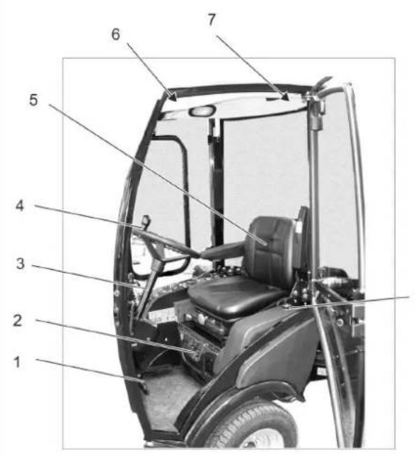

1 Pedals*
2 Ventilation/air conditioning (option) *
3 Steering column *
4 Steering wheel
5 Driver's seat
6 Ceiling panel
7 Emergency hammer
8 Drive light/direction indicator
9 W i p e r
10 Work light
11 Beacon lamp
12 Rear-view mirror
13 Door handle *
14 Tank lid
15 Hydraulic oil sight glass
16 Rear vehicle
17 Rear lights
18 Balance weight with attachment hitch
19 Hydraulic couplings main PTO
20 Implement frame
21 AUX connection
22 Container windshield washer system
23 Tank indicator
$$ F = \text {f u l l} $$
$$ E = e m p t y $$
- see detailed view below
5.2.1 Ventilation/air conditioning (option)
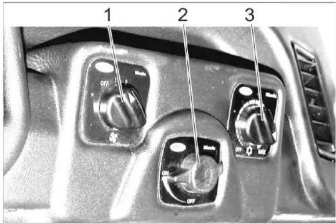
1 Switch ventilator blower
2 Temperature regulator of heater
3 Cooling capacity regulator (option)
5.2.2 Ceiling panel
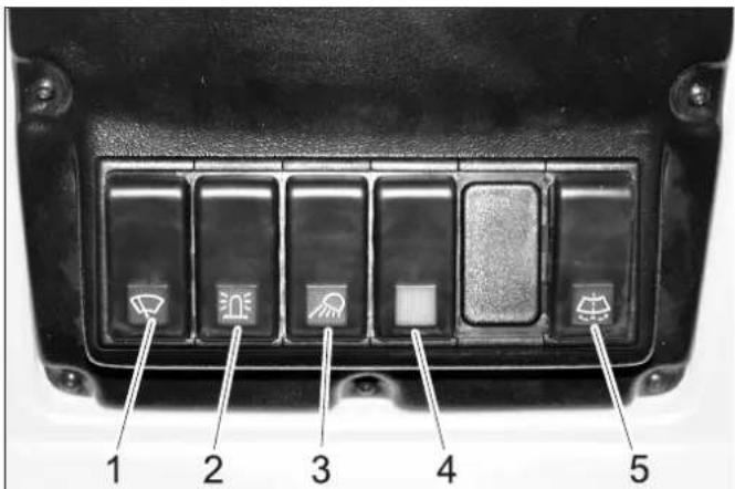
1 Switch for windshield wiper, 2 steps
2 Switch for beacon warning lamp
3 Switch for working lamp
4 Switch for option (e.g. heated outside mirrors)
5 Button for windshield wiper system
5.2.3 Door handle
1 Interior door unlock
5.3 Steering column
1 Ventilation
2 Indicator lamp for direction indicator
3 Switch for warning system
4 Clamp screw for steering wheel height adjustment
5 Operating hours counter, working hydraulics
6 Indicator lamp for parking brakes
7 Display, float position AUX 1
8 Clamp screw for steering wheel inclination adjustment
9 Display, float position, front power lifter
10 Multi-functional lifter for lights, indicators and horn
5.4 Multi-functional lifter for lights, indicators and horn
Horns: Press the lever up
- Indicator: Lever to the right of left
- Parking light and dipped beam: Rotate the ring (anticlockwise)
- High beam: Push the lever forward with the dipped beam switched on
- Flasher: Pull the lever backwards
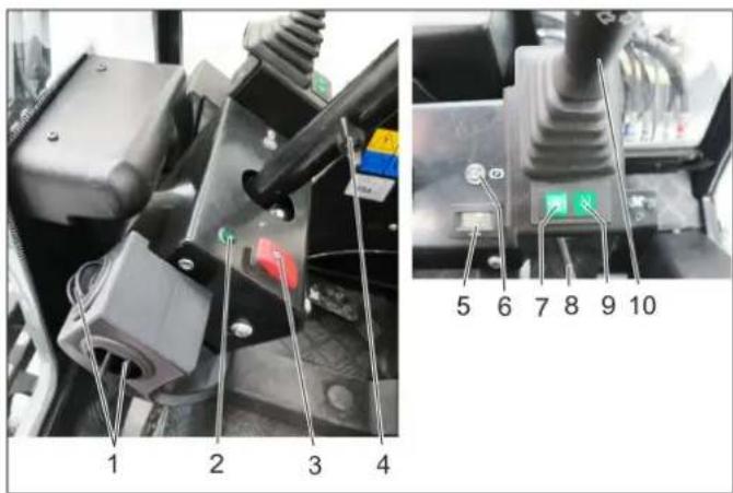
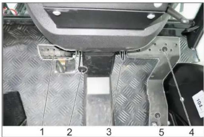
5.5 Pedals

1 Brake pedal
2 Locking mechanism of brake pedal (emergency brake)
3 Stop work speed
4 Accelerator pedal, forwards
5 Accelerator pedal, reverse
5.5.1 Apply parking brake
Press the brake pedal all the way.
Put the lock.
Release the brake pedal.
5.5.2 Release parking brake
Press the brake pedal all the way.
Unlock the lock.
Release the brake pedal.
5.6 Lowering speed control valve (option)
The rotary knob for the lowering speed is used to adjust the lowering speed of the front implement frame.
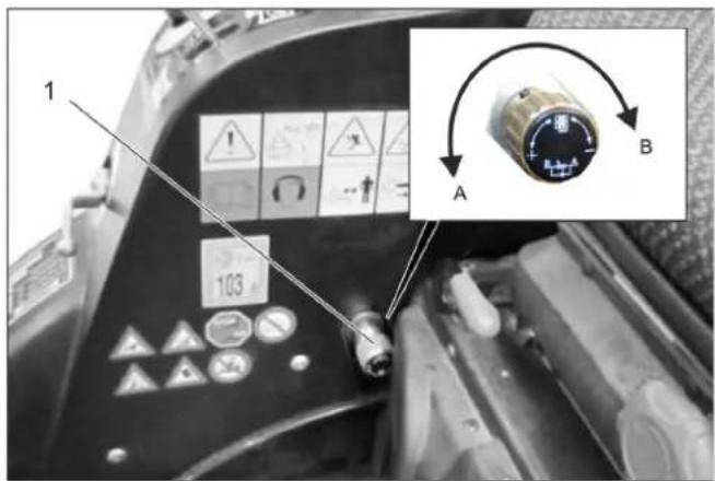
1 Rotary knob lowering speed control valve
A Direction of rotation "Increase lowering speed"
B Direction of rotation "Decrease lowering speed"
Turning into the direction of rotation B to the limit stop locks the front power lift.
Note
Is required for transport runs on public roads in order to lock the front power lift and thus the lowering of the attachments.
5.7 Connections
Terminology AUX: Auxiliary = additional control valve Terminology hydraulic PTO: Power Take Off = hydraulic power output
Terminology electric PTO: Power Take Off = electric power output
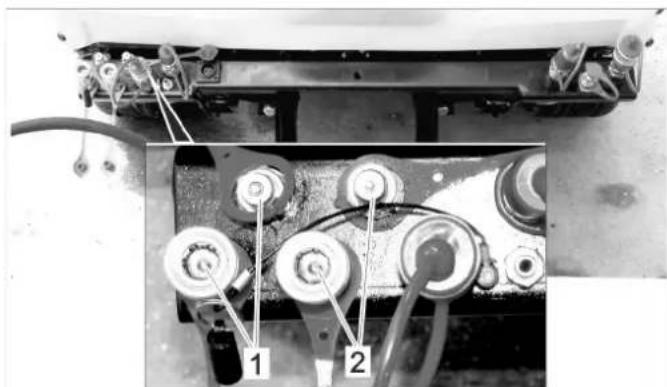
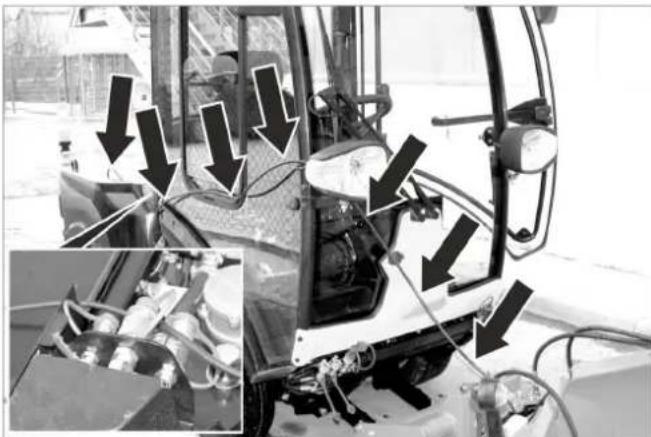
5.7.1 Front
| AUX 2 | AUX 1 | 2.PTO | H2O | E 1/12V |
| 1 | 2 | 3 | 4 | 5 |
1 Hydraulic couplings AUX2
2 Hydraulic couplings AUX1
3 Hydraulic couplings 2nd PTO
4 Water coupling (e.g. for broom coupling)
5 Socket outlet E1
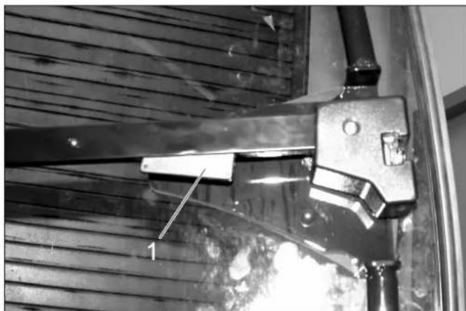
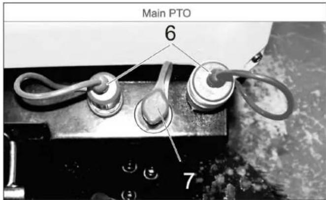
6 Hydraulic couplings main PTO
7 Leakage coupling
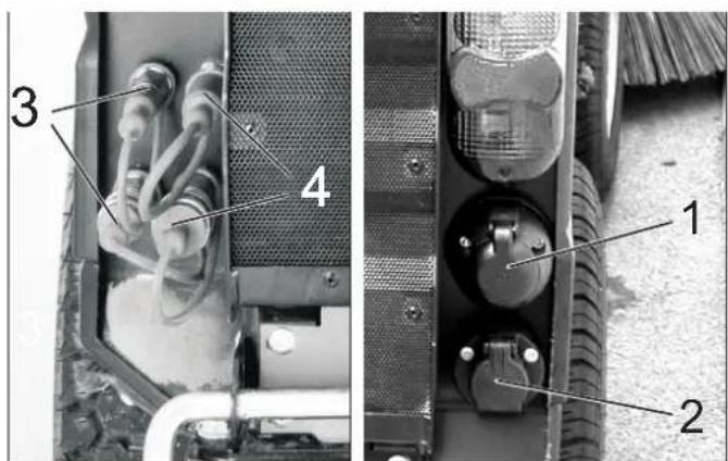
5.7.2 Back
1 Socket E4 rear, 7-way
2 Socket E3 rear, 3-way
3 Hydraulic couplings AUX2
4 Hydraulic couplings 2nd PTO
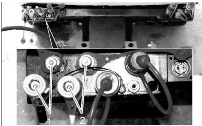
5.7.3 On the rear cart
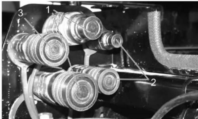
1 Hydraulic couplings main PTO
2 Hydraulic couplings AUX2
3 Leakage coupling
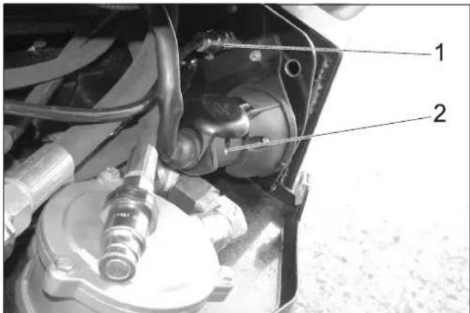
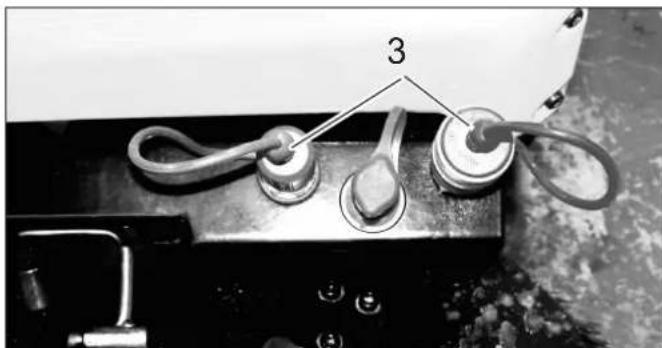
1 Water coupling
2 Socket E3 front
5.8 Console (for device with driver cabin)
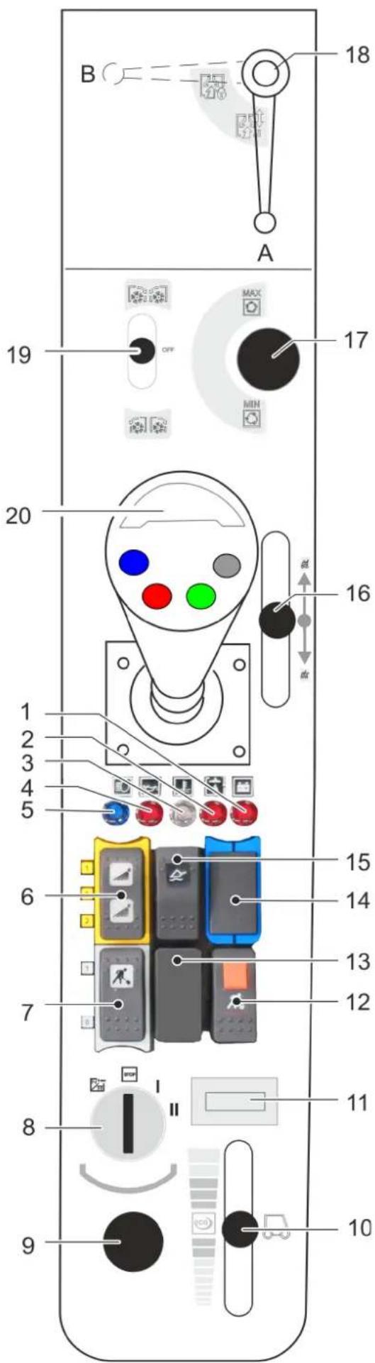
1 Warning lamp for battery charge indicator
2 Warning lamp hydraulic oil pressure
3 Warning light coolant temperature
4 Warning lamp oil pressure
5 Indicator lamp for high beam
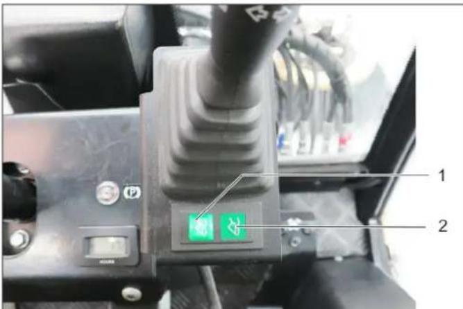
6 Switch
Position 1: Water coupling front on
Position 0: Water coupling front off
Position 2: Switch on water circulation system (option)
7 Buttons
Position 1: Work hydraulics Main PTO on
Position 0: Work hydraulics Main PTO off
8 Ignition lock
9 On board socket 12 V
10 Hand throttle lever
11 Operating hours meter for motor
12 Pushbutton with locking mechanism
Work hydraulics Main PTO constantly on
Function only in connection with locked parking brake and button 7
13 Not assigned
14 Not assigned
15 Main switch floating position
16 Control lever for optional waste container
17 Setting speed PTO
18 When working with the suction mouth (option)
Position A - suction mouth not locked
Position B - suction mouth locked
19 Control lever 2.PTO connection
For optional side brushes:

Side brush on, sweep

be brush stop.

Side brush on, reversal of rotation
20 Joystick
5.8.1 Ignition switch
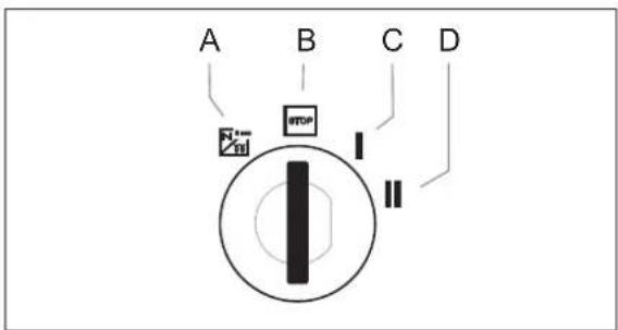
A Filament symbol : Pre-heat
B Position STOP: Engine off
C Position 1: Ignition on
D Position 2: Start the engine
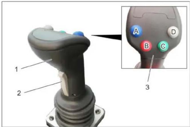
5.9 Joystick function (for device with driver cabin)
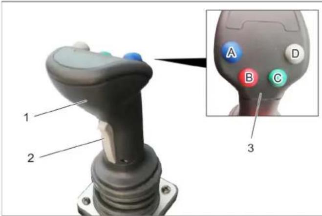
1 Joystick
2 Front button
3 Function keys
A - blue
B-red
C - green
D - grey
The following are controlled with the joystick: Implement frame
AUX 1 connection
AUX 2 connection
AUX connection, electrical 12 V
When selecting a float position, the corresponding display lights up.
5.9.1 Operations
| Front power lifter (with float position) | ||
| Main switch, float position (console) | Function button | Joystick |
| Activate Press the grey button (D) | --- | |
| Front power lifter (without float position) | |
| Main switch, float position (console) | Function button Joystick |
| Deactivate --- to the front / to the rear | |
| AUX 2 connection (with float position) | ||
| Main switch, float position console) | Function button | Joystick |
| Activate Press the | green button (C) | --- |
| AUX 2 connection (without float position) | ||
| Main switch, float position console) | Function button | Joystick |
| Deactivate --- move to the left / right | ||
| AUX 1 connection | ||
| Button to the front (joystick) | Function button | Joystick |
| Press and hold --- | move to the left / | right |
| AUX connection, electrical 12 V | ||
| Button to the front (joystick) | Function button | Joystick |
| --- Press the blue or red function but-tons (A/B) | --- | |
5.9.2 Display, float position
1 Display, float position AUX 1
2 Display, float position, front power lifter
When selecting a float position, the corresponding display lights up.
5.10 Console (for device with protective bar)
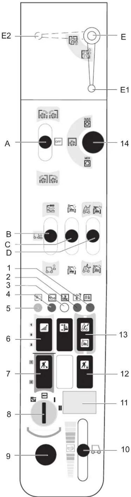
A Control lever, snaps in place 2.PTO connection: forward/reverse
B Control lever Front power lift up/down
C Control lever AUX 1 connection
D Control lever AUX 2 connection Multifunction lever available in connection with front appliance carrier and weed broom (optional)
E For working with the suction port (optional) Position E1 - suction port not locked Position E2 - suction port locked
1 Warning lamp for battery charge indicator
2 Warning lamp hydraulic oil pressure
3 Warning light coolant temperature
4 Warning lamp oil pressure
5 Indicator lamp for high beam
6 Switch Position 1: Water coupling front on Position 0: Water coupling front off Position 2: Switch on water circulation system (option)
7 Buttons Position 1: Work hydraulics Main PTO on Position 0:Work hydraulics Main PTO off
8 Ignition lock
9 On board socket 12 V
10 Hand throttle lever
11 Operating hours meter for motor
12 Pushbutton with locking mechanism Work hydraulics Main PTO constantly on Function only in connection with locked parking brake and button 7
13 Switch-over AUX 2 front/back
14 Setting speed PTO
5.10.1 Ignition switch
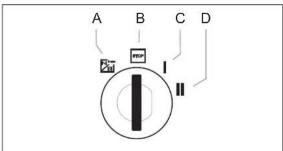
A Filament symbol : Pre-heat
B Position STOP: Engine off
C Position 1: Ignition on
D Position 2: Start the engine
5.11 Operating lever function (for device with protective bar)
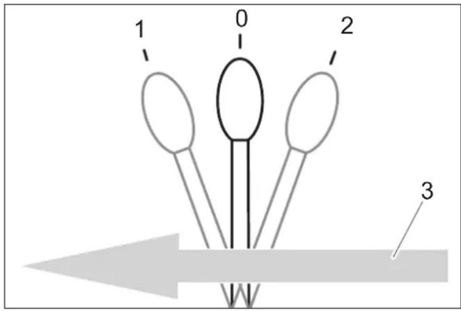
5.11.1 Function control lever A
0 Resting position
1 Attachments connected to 2.PTO forward, lever snaps in place
2 Attachments connected to 2.PTO reverse, lever snaps in place
3 Forward travel direction
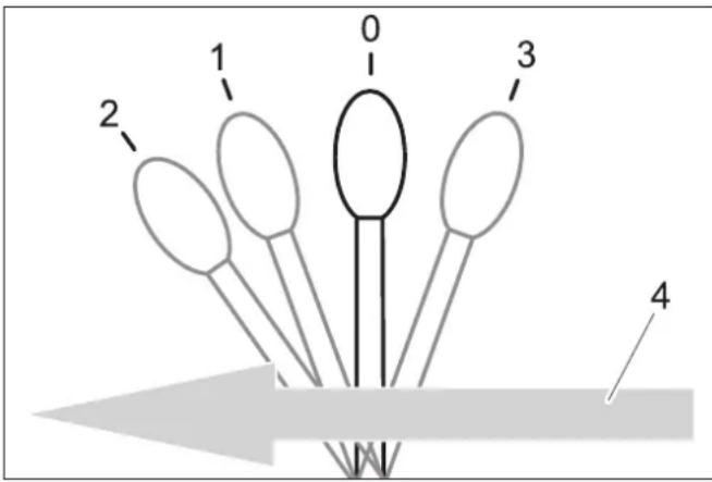
5.11.2 Function control lever B
0 Resting position
1 Front power lift is lowered, lever does not snap in place CAUTION Risk of damage! In this lever position the upgrade kit (option) can not evade ground unevenness.
2 The front power lift is lowered and is in the floating position, working equipment follows the ground (e.g. broom), lever snaps in place
3 Front power lift is raised, lever does not snap in place
4 Forward travel direction

5.11.3 Function control lever C
0 Resting position
1 Attachments connected to AUX 1 towards the front, lever does not snap in place
2 Attachments connected to AUX 1 towards the rear, lever does not snap in place
3 Forward travel direction
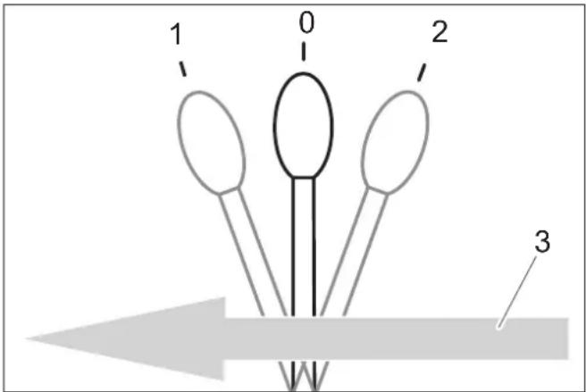
5.11.4 Function control lever D
0 Resting position
1 Attachments connected to AUX 2 towards the front, lever does not snap in place
2 Attachments connected to AUX 2 towards the rear, lever does not snap in place
3 Forward travel direction
6 Before Startup
6.1 Prior to initial start-up
Attach the document pouch to the rear window as instructed in the enclosed instructions.
6.2 Refuelling
Danger
Risk of explosion!
- Do not refuel the machine in enclosed spaces.
Smoking and open flames must be strictly avoided. - Ensure that no fuel reaches the hot open surfaces.
Switch off engine.
Open fuel filler cap.
Fill in diesel.
Only use the fuels specified in the Operations Manual.
Insert the fuelling gun as deep as possible into the fuel nozzle. Do not add any more fuel once the fuelling gun stops according to the settings.
Wipe off any spilt fuel and close fuel filler cap.
6.2.1 Fuelling using a can
Estimate the fuel requirement in order to avoid overflows.
6.3 Fill the windshield wiper system
only device with driver cabin
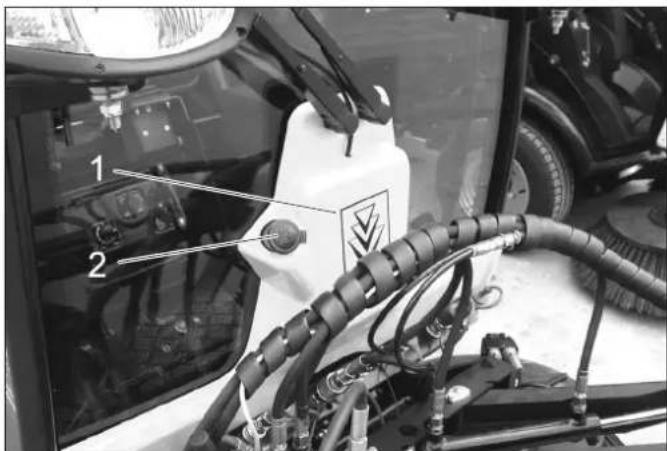
1 Container windshield washer system
2 Cover
Remove the lid.
Fill in liquid.
Close the lid.
6.4 Adjusting driver's seat
△DANGER
Danger of accident. Do not adjust the driver's seat while driving.
6.4.1 Standard seat
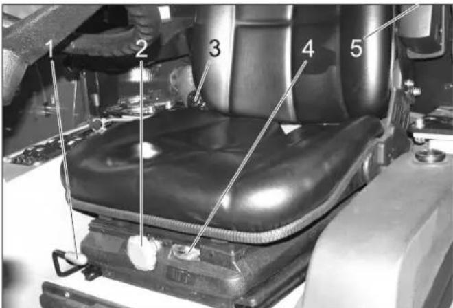
1 Lever for seat adjustment
2 Rotary handle for spring resistance
3 Inclination adjustment back rest
4 Display of spring setting
5 Adjustment wheel arm rest height
Sit on the driver's seat.
Pull the seat adjustment lever up and slide the seat into the desired position.
Release the seat adjustment lever and lock the seat in place.
Set the inclination of the back-rest with the rotary handle for back-rest inclination.
Adjust the height of the arm rests via the adjustment wheels.
Adjust the rotary handle of the spring resistance so that the pointer of the spring resistance display is in the green area.
6.4.2 Comfort seat (optional)
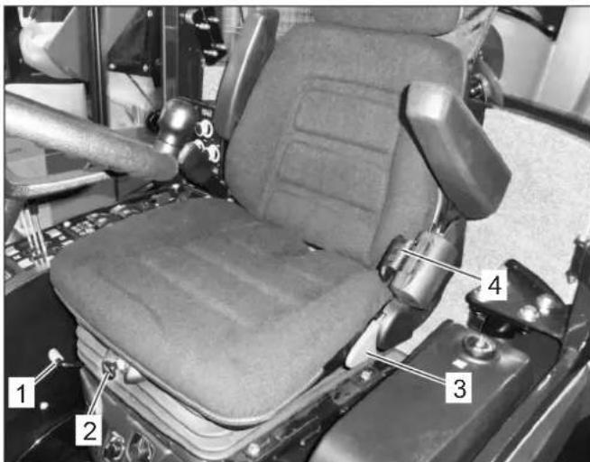
1 Lever for seat adjustment
2 Height adjustment
To lower: Pull out the knob
To lift: Push the knob (while the motor is running)
3 Inclination adjustment back rest
4 Seat belt
The damping of the driver seat takes place automatically.
6.5 Set the steering wheel position 6.6 Prior to start/safety test
DANGER
Danger of accident. Do not adjust the steering wheel position while driving.
1 Clamp screw for steering wheel height adjustment 2 Clamp screw for steering wheel inclination adjustment
Loosen the clamp screw for steering wheel height adjustment.
Set the steering wheel to the desired height.
Tighten clamping screw.
Loosen the clamp screw for steering wheel inclination adjustment.
Set the desired inclination of the steering wheel column.
Tighten clamping screw.
DANGER
Risk of accidents, injuries. If one point of the safety check is not fulfilled, the appliance must not be taken into operation, but must be repaired.
The following safety tests must be conducted prior to each operation:
6.6.1 Safety check
Perform the safety check while the ignition is switched on (position 1).
With released parking brake: Release accelerator pedal, switch off work hydraulics Main PTO - the motor must not start when turning the ignition key (position 2).
With actuated brake pedal: Switch on work hydraulics
Main PTO - the motor must not start when turning the ignition key (position 2).
With running motor: Switch on work hydraulics Main PTO, relieve driver seat - the work hydraulics Main PTO must switch off
6.7 Daily maintenance tasks
Carry out the daily maintenance tasks (see section "Maintenance and Care").
7 Operation
△DANGER
Danger of crushing. Make sure that no persons are present near the arm hinges.
Danger of burns, crushing. Only use the appliance if all casing parts have been attached.
CAUTION
Risk of damage by overheating of the power transmission and the brake. Only use the brake pedal during travel, if the appliance does not stop when the accelerator pedal is released or briefly activated.
Danger of damage due to lack of lubrication. If the oil pressure warning lamp lights up during operation, switch the engine off immediately and remediate the malfunction.
Risk of damage due to overheated engine or overheated hydraulic oil. If the warning lamps for engine temperature or hydraulic oil temperature lights up, set the engine speed to idle (do not turn the engine off) and perform the measures in the Chapter "Malfunctions".
7.1 Driving
WARNING
The device has a central pendulum joint in order to provide maximum manoeuvrability.
This enables both vehicle halves to move laterally to the direction of travel independently from one another.
Due to this special feature, the driver does not receive timely feedback from the rear half of the vehicle. It is for this reason that the driver has to use the mirrors to watch the movements of the rear half of the vehicle.
Vehicles with articulated steering are much more sensitive to steering movements than passenger cars – particularly when taking bends at high speed, on snow, ice and wet/loose ground as well as during turning manoeuvres on slopes.
It is therefore extremely difficult to stabilise a vehicle with articulated steering by countersteering!
1 Brake pedal
2 Locking mechanism of brake pedal (emergency brake)
3 Stop work speed
4 Accelerator pedal, forwards
5 Accelerator pedal, reverse
7.1.1 Release parking brake
Press the brake pedal all the way.
Turn the lock toward the rear.
Release the brake pedal.
7.1.2 Start the engine
Remove your foot from the accelerator pedal.
Set engine speed to MIN position.
Press the brake pedal all the way down.
The indicator lamp for the emergency brake must be illuminated.
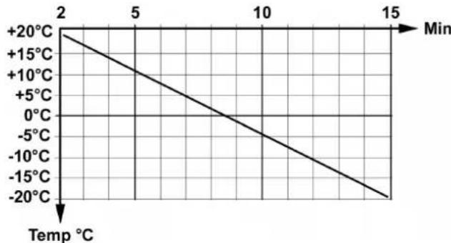
With low exterior temperatures, turn the ignition key to pre-heating setting for about 3 seconds.
Turn the ignition key to "Start engine" and hold it there until the engine starts up.
Release the ignition key. The ignition key turns to position "1", engine on.
Release the brake pedal.
CAUTION
Risk of damage by overheating of the power transmission and the brake. Do not drive appliance while brake is activated.
After a cold start, let the appliance warm up while the engine speed is set to MIN, so that the hydraulic oil can reach operating temperature.
The pre-heating time depends on the ambient temperature and can be read from the diagram below.
7.1.3 Driving
ATTENTION
The speed is reduced when you release the gas pedal; a property that is different to passenger cars.
In transport mode, the speed reduction due to braking when you let go of the gas pedal is lower than in work mode.
Raise the working machine.
Raise the suction opening and the side-brushes (for sweepers).
Set engine speed to ECO.
Press accelerator pedal down slowly.
Control the driving direction with the steering wheel.
7.1.4 Stop
Release the accelerator pedal or drive backwards for a moment, the machine brakes automatically and stops.
Only use the brake pedal if the appliance does not stop in spite of applying the above measures.
CAUTION
Risk of damage to the drive system. Use the brake only in emergencies and as an emergency brake while the appliance is not moving, not as an operational brake.
7.1.5 Driving over obstacles
WARNING
Risk of damage! Raise the side-brushes and the suction opening before overtaking hurdles.
Obstacles up to 150 mm in height:
Bypass the obstacles slowly and carefully at an angle of 45^ .
Obstacles more than 150~mm in height:
Only drive over these obstacles using a suitable ramp.
Warning
Risk of damage! Ensure that the vehicle does not get stuck up.
7.2 Turn off device
Raise the work machine.
Stop the machine.
Switch off PTO.
Set engine speed to MIN position.
Let the engine idle for 1 to 2 minutes.
Turn ignition key to "STOP" and remove it.
Activate parking brake.
7.3 Frost protection
If frost is expected, check whether there is enough antifrosting agent in the cooling water.
7.4 Transport
WARNING
Risk of injury and damage! Observe the weight of the appliance when you transport it.
Risk of accident: The appliance must be secured against slippage during transport.
CAUTION
Risk of damage! Never attach the appliance to the brush system or tow it (for sweepers).
Switch the appliance off and lock the emergency brake.
Secure the vehicle on the fixing eyelets on the left and the right using tie down straps.
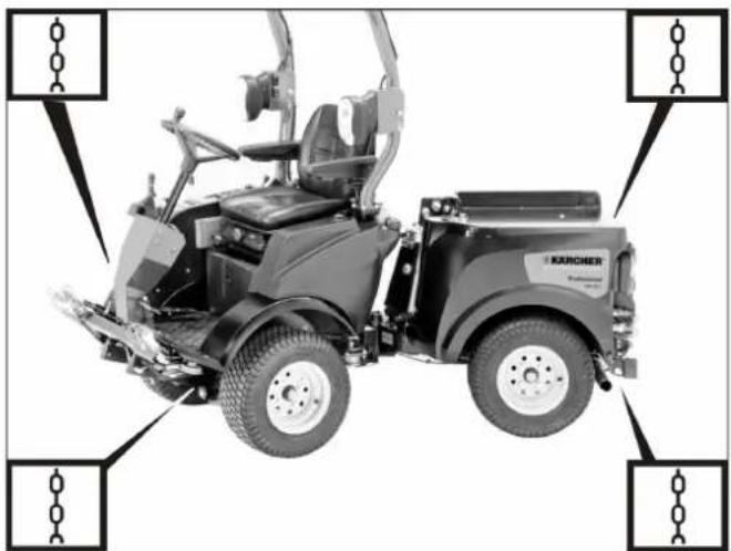
Illustration is symbolic
8 Attachment sets
In this chapter, a selection of the most common attachment kits are listed and the attachment is shown on the device.
For further questions concerning other attachment kits, please contact Kärcher.
Before installing and operating the attachment kit, be sure to read the separate instructions and the safety instructions for the attachment kit.
Currently the following attachments are available for the MIC 26:
- Mower deck 125 cm
Mower deck 135 cm
- Front brush roller
Snow plow
-
Spreader
-
Loading platform
-
Sweeping device with 2 brooms and waste container
-
Sweeping device with 3 brooms and waste container
-
Weed broom (only in connection with a front appliance carrier)
Balance weight at the back
- Towing hitch
△WARNING
Rear attachments and load statuses have an impact on the vehicle's centre of gravity and thus on the driving characteristics.
In the case of modifications, particularly when converting from winter to summer operation and in the case of changeable load statuses, the driver must adjust to changed driving characteristics.
Particularly when transporting fluids, additional surge movements can occur which rock the vehicle.
8.1 Operations
Operation of the attachment unit is done with the joystick; for more about this, see the "Joystick function" chapter.
8.2 Mower 125 cm
8.2.1 Connecting the hydraulic lines
1 Hydraulic couplings main PTO
Hydraulic hoses, knife drive
2 Socket outlet E1
Cable for cutting height adjustment
8.2.2 Operations
Operation of the attachment unit is done with the joystick; for more about this, see the "Joystick function" chapter.
8.2.3 Prerequisites for operation
-
The balance weight (option) must be attached to the rear of the machine for driving on public roads.
-
Set the motor rpm to high.
Note:
The wear on the ground can be reduced by using the upgrade kit for grass tyres (2.851-089.0).
Removing the waste container/fresh water tank will increase the driving stability and the driver's view.
8.2.4 After mowing
Lower the working appliance and the suction opening.
Clean the top surface of the suction opening with compressed air (for sweepers).
Clean the cooler.
8.3 Mower 135 cm
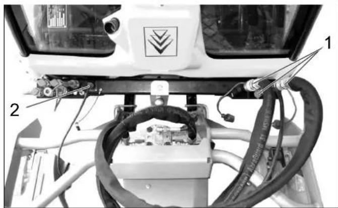
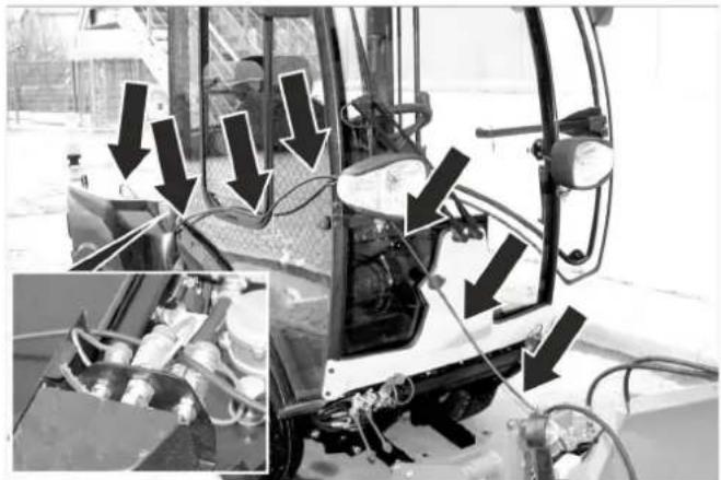
8.3.1 Connecting the hydraulic lines
1 Hydraulic couplings AUX2
Hydraulic hoses for rear ejector (marked with cable ties)
2 Hydraulic couplings AUX1
Hydraulic hoses, cutting height
3 Hydraulic couplings main PTO
Hydraulic hoses, knife drive
8.3.2 Operations
Operation of the attachment unit is done with the joystick; for more about this, see the "Joystick function" chapter.
8.3.3 Prerequisites for operation
-
The balance weight (option) must be attached to the rear of the machine for driving on public roads.
-
Set the motor rpm to high.
Note:
The wear on the ground can be reduced by using the upgrade kit for grass tyres (2.851-089.0).
Removing the waste container/fresh water tank will increase the driving stability and the driver's view.
8.3.4 After mowing
Lower the working appliance and the suction opening.
Clean the top surface of the suction opening with compressed air (for sweepers).
Clean the cooler.
8.4 Front brush roller
8.4.1 Connecting the hydraulic lines
1 Hydraulic couplings AUX2
Hydraulic couplings, swivel drive
2 Hydraulic couplings main PTO
Hydraulic couplings, brush roller drive
3 Hydraulic hoses, brush roller drive
4 Hydraulic hoses, swivel drive
8.4.2 Operations
Operation of the attachment unit is done with the joystick; for more about this, see the "Joystick function" chapter.
8.5 Snow removal shields
8.5.1 Connecting the hydraulic lines
1 Hydraulic couplings AUX2
2 Hydraulic couplings AUX1
8.5.2 Operations
Operation of the attachment unit is done with the joystick; for more about this, see the "Joystick function" chapter.
8.5.3 Connect the marker lamps (option)
Route the cables as shown above.
Connect the plug on the rear of the sweeper.
8.5.4 Prerequisites for operation
- If no caster is attached, the balance weight (option) must be attached to the rear of the machine for driving on public roads, when the waste container/water tank is removed.
Note:
Removing the waste container/fresh water tank will increase the driving stability and the driver's view.
8.6 Snow blower
8.6.1 Connecting the hydraulic lines
1 Hydraulic couplings AUX2
2 Hydraulic couplings AUX1
3 Hydraulic couplings main PTO
8.6.2 Operations
Operation of the attachment unit is done with the joystick; for more about this, see the "Joystick function" chapter.
8.6.3 Connect the marker lamps (option)
Route the cables as shown above.
Connect the plug on the rear of the sweeper.
8.6.4 Prerequisites for operation
- If no caster is attached, the balance weight (option) must be attached to the rear of the machine for driving on public roads, when the waste container/water tank is removed.
Note:
Removing the waste container/fresh water tank will increase the driving stability and the driver's view.
8.7 Caster
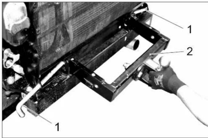
8.7.1 Mount the attachment block
Shut the motor off, remove ignition key.
1 Safety pin
2 Attachment block
Unlock the safety bolt by turning it and pull it out.
Slide the attachment block into the two square pipes on the rear of the machine.
Slide in the safety bolt and lock it by turning it.
Insert the spray guard to protect the radiator from sprayed materials.
8.7.2 Fasten the roller caster
1 Holding pin
2 Safety pin
3 Folding plug
Pick the roller caster up and hook the holding pins into the guide slots at the bottom of the mounting block. Use the guide slots located closer to the vehicle.
Align the roller caster and fasten using the safety bolt.
Secure the safety block against sliding out with the folding plug.
8.7.3 Attach the plate caster
1 Holding pin
2 Safety pin
3 Folding plug
Same attachment as the roller caster, except that the guide slots furthest from the vehicle are used.
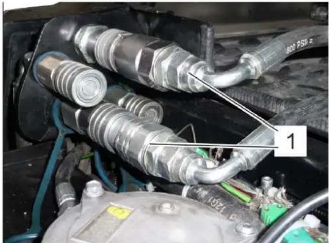
8.7.4 Connecting the hydraulic lines
Remove the protective caps from the hydraulic coupling and connect the hydraulic hoses with the respective couplings.
Connect the protective caps to each other to protect from contamination.
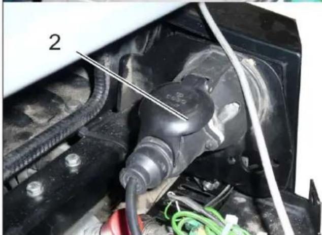
8.7.5 Connecting the tail lights
Connect the plug on the rear of the sweeper.
Secure the cable if necessary to prevent it from being pulled in by moving parts.
8.7.6 Operations
Switch on the PTO to switch on the control
8.7.7 Prerequisites for operation
- Set the motor speed to "eco", the lower level of the range.
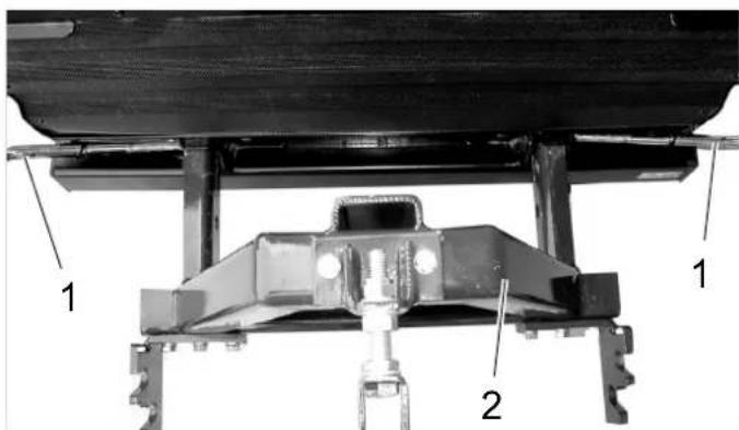
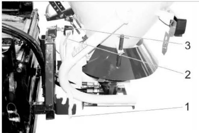
8.8 Chassis mounted spreader
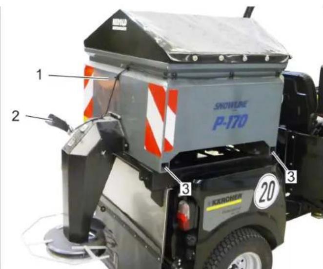
1 Chassis mounted spreader
2 Work light
3 Retainer for support (4x)
8.8.1 Securing the chassis mounted spreader
Crank up the chassis mounted spreader with the supports to the required height until the rear retainer of the carrier vehicle fits underneath.
Open the safety bolts at the chassis mounted spreader prior to placing it on the vehicle, for this purpose, turn the lever on the inside in a counter-clockwise direction (left and right).
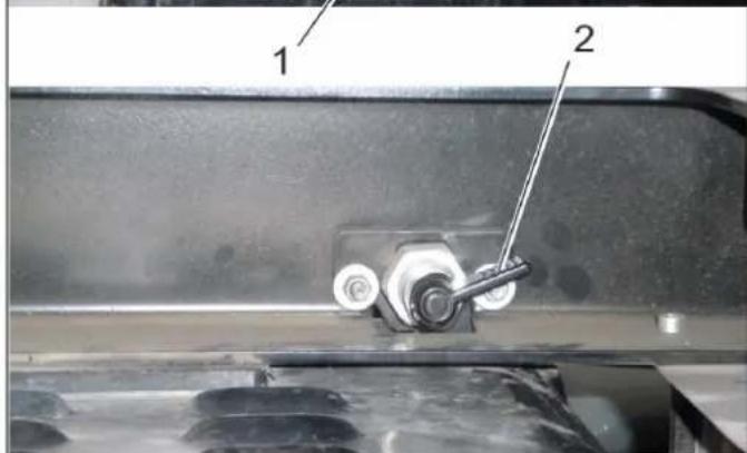
1 Safety pin
2 Lever
Position the vehicle under the chassis mounted spreader that is standing on the supports.
Lower the chassis mounted spreader into the guides of the rear structure.
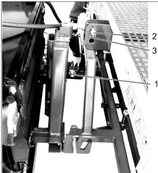
When attaching the chassis mounted spreader to the vehicle for the first time, the left and right front guide must be adjusted.
1 Screw (one visible, two covered)
2 Guidance
Adjust guide: Loosen 3 screws at the front side by approx. 1 rotation (left and right).
Slide the chassis mounted spreader all the way to the front until the safety bolts in the back can be locked.
Tighten the visible screw.
Unlock the safety bolts and slide the chassis mounted spreader slightly to the back, tighten the remaining screws.
Slide the chassis mounted spreader all the way to the front and lock it with safety bolts in the back.
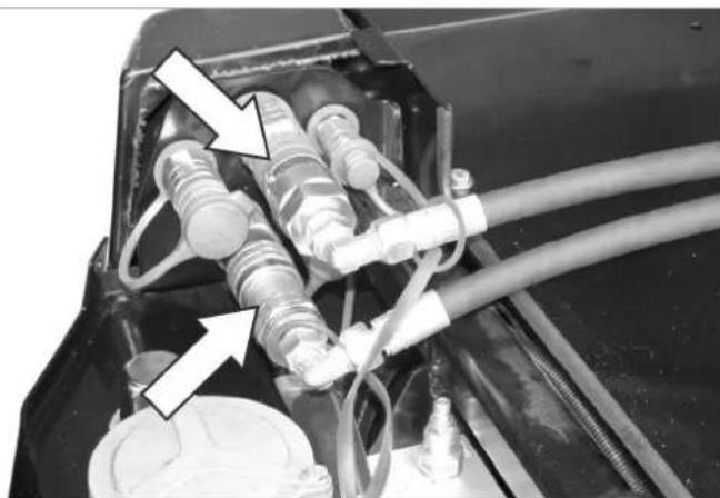
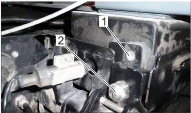
1 Hydraulic couplings main PTO
2 Electric connectors
Connect the hydraulic hoses and electrical plug with the respective couplings.
8.8.2 Operations
Switch on the PTO to switch on the control
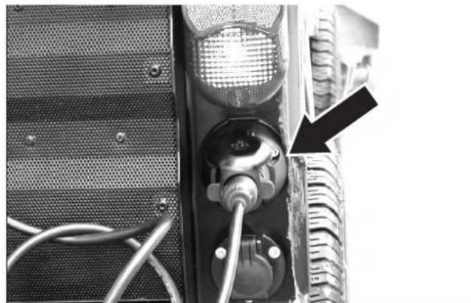
8.8.3 Connecting the work light
Plug the plug of the lamp into the socket at the hind carriage.
Switch on the working light with the switch.
8.9 Balance weight without attachment hitch
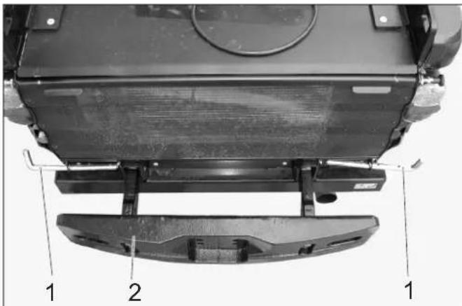
1 Safety pin
2 Counterweight
Unlock the safety bolt by turning it and pull it out toward the side.
Slide the counter weight into the square pipes of the machine frame.
Slide in the safety bolt and lock it by turning it.
8.10 Balance weight with attachment hitch
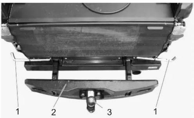
1 Safety pin
2 Counterweight
3 Towing hitch
Unlock the safety bolt by turning it and pull it out toward the side.
Slide the counter weight with the attachment hitch into the square pipes of the appliance frame.
Slide in the safety bolt and lock it by turning it.
8.10.1 Towing hitch
The permissible drawbar and drawing loads of the machine are indicated in the Chapter "Technical Specifications".
8.11 Towing hitch
1 Safety pin
2 Towing hitch
Unlock the safety bolt by turning it and pull it out toward the side.
Slide the lorry hitch into the square pipes of the machine frame.
Slide in the safety bolt and lock it by turning it.
The permissible drawbar and drawing loads of the machine are indicated in the Chapter "Technical Specifications".
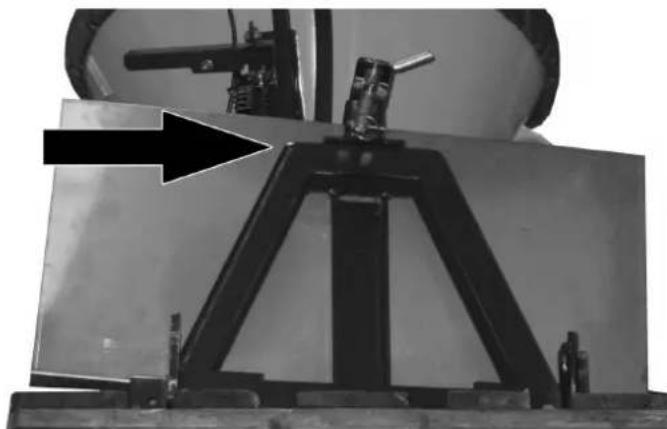
8.12 Coupling triangle
The coupling triangle enables the attachment of upgrade kits already available at the municipalities.
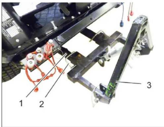
1 Implement frame
2 Safety pin
3 Coupling triangle
8.12.1 Securing the coupling triangle
Attach the coupling triangle to the front power lift and secure it by means of safety bolts.
8.12.2 Prerequisites for operation
Depending on the weight of the mounted attachment, counterbalance weights (option) must be attached to the back of the appliance.
- Establish hydraulic connections depending on the attachment. Refer to the operating instructions of the attachment.
8.12.3 Operations
To raise and lower, operate the front power lifter with the joystick.
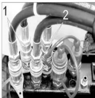
8.13 Weed broom
only device with driver cabin
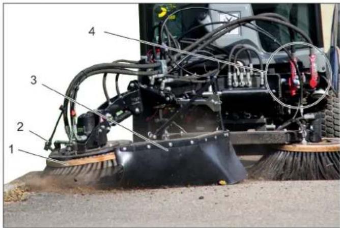
1 Weed broom
2 Water-spraying equipment
3 Splash guard
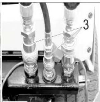
4 Hydraulic couplings main PTO
8.13.1 Proper use
The upgrade kit weed broom is attached to the front appliance carrier.
It is used to remove:
- encrusted dirt
Growth between paver stones
and similar cleaning tasks.
The upgrade kit can be used in conjunction with the 2-broom system.
The weed broom is suitable for all surfaces.
Street surfaces or similar surfaces can become scratched, even if the weed broom is used in floating position.
8.13.2 Important notes
When driving on public roads, you must adhere to the local regulations.
Adhere to the local accident prevention guidelines and safety notes.
Follow the safety and operating instructions in the towing vehicle manual.
8.13.3 Prerequisites for operation
Front power lift must be attached to the vehicle.
8.13.4 Installing the weed broom
Attach the completely pre-assembled weed broom to the front power lift, and secure it.
Note
If the weed broom is supplied as an attachment kit, then assemble it beforehand in accordance with Installation instructions 0.083-359.0 enclosed with the attachment kit.
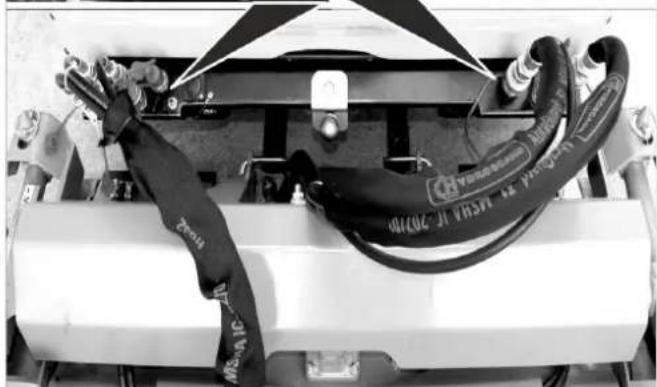
Establish hydraulic connections PTO, AUX 1 and AUX 2 on the vehicle.
Create a water connection.
8.13.5 Operation 8.13.6 Joystick function
DANGER
Risk of injury if you touch the rotating weed broom. Watch for sufficient safety clearance to people when adjusting and working.
Risk of injury on account of projected rocks or dirt. Correctly adjust the spray guard and keep sufficient clearance to persons.
△DANGER
Accident risk on account of decreased steering performance. When you press down on the weed broom, the weight it taken off the front wheels. This can lead to a decreased steering effect. In this case, lift the weed broom up immediately.
The weed broom and the front appliance carrier are operated using the joystick.
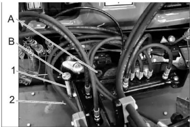
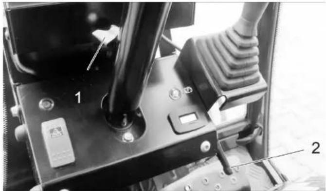
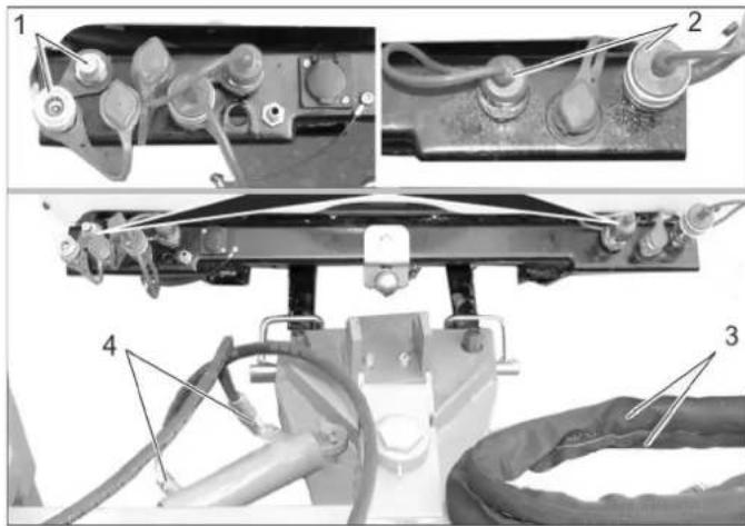
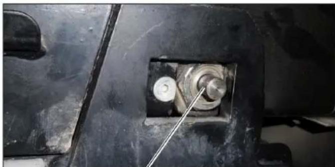
1 Bolt for transport lock
2 Spring pin
A O p e r a t i o n
B Transport
Pull out the transport lock bolt.
Swivel the front appliance carrier to the right.
Insert the transport lock bolt into the operating position and secure with spring cotter pin.
Lower the front appliance carrier until the broom touches the ground.
Tighten the screw.
Tighten the locknut.
Start the motor.
Raise the front appliance carrier.
Roll (tilt at the side) the weed broom into the required position, tilt it (forwards) and swivel it.
For cleaning work, switch on the working hydraulics for the main PTO. The weed broom rotates.
Lower the front appliance carrier into the floating position.
Note:
Usually, the front appliance carrier is lowered into the floating position. If you desire an increased cleaning performance, the weed broom can be briefly pushed down.
Perform cleaning process.
1 Joystick
2 Front button
3 Function keys
A - blue
B-red
C -green
D - grey
The following are controlled with the joystick:
Implement frame
AUX 1 connection
AUX 2 connection
AUX connection, electrical 12 V
When selecting a float position, the corresponding display lights up.
8.13.6.1 Operations
Weed broom
| Front power lifter (with float position) | ||
| Main switch, float position (console) | Function button | Joystick |
| Activate Press the grey button (D) | --- | |
| Front power lifter (without float position) | |
| Main switch, float position (console) | Function buttonJoystick |
| Deactivate --- to the | front / to therear |
| Weed broom arm (with float position) | ||
| Main switch, float position (console) | Function button | Joystick |
| Activate Press the | green button (C) | --- |
| Press / lift the weed broom arm (without float posi- tion) | ||
| Main switch, float position console) | Function button | Joystick |
| Deactivate Press and hold move to the left / right | ||
| Swivel in / out the broom arm | ||
| Button to the front (joystick) | Function button | Joystick |
| --- --- move to the left / | right | |
| Tilt the broom head (forwards) | ||
| Function button Blue | Function button Red | Joystick |
| Press and hold --- | move to the left / | right |
| Roll the broom head (tilt at the side) | ||
| Function button Blue | Function button Red | Joystick |
| --- Press and hold | move to the left / | right |
8.13.7 Transport run
WARNING
Increased injury risk if working with unfavourably placed weed broom. To minimise the injury risk, align the broom as described below while you work.
Raise the front appliance carrier.
Tilt the broom forwards.
Swivel in the broom in a clockwise direction.
Insert the transport lock bolt into the transport position and secure with spring cotter pin.
Mount the spray guard so that the broom is covered.
9 Storage
△WARNING
Risk of injury and damage! Note the weight of the appliance in case of storage.
If the vehicle is not used for a longer period of time, observe the following points:
Park the vehicle at a safe, level and dry place.
Turn ignition key to "STOP" and remove it.
Secure vehicle against rolling away, lock parking brake.
Change the engine oil and the oil filter.
If frost is expected, check whether there is enough antifrosting agent in the cooling water.
Charge battery approx. every 2 months.
Disconnect the negative terminal of the battery if the appliances is not used for more than 4 weeks.
10 Care and maintenance
10.1 General notes
First switch off the appliance and remove the ignition key before performing any cleaning or maintenance tasks on the appliance, replacing parts or switching over to another function.
The battery must be disconnected prior to working on the electrical system.
Lockparkingbrake.
Maintenance work may only be carried out by approved customer service outlets or experts in this field who are familiar with the respective safety regulations.
10.2 Panels
10.2.1 Remove/attach engine panels
WARNING
Risk of burns Let the appliance cool off before removing the covers.
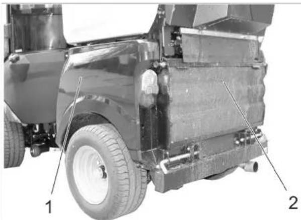
1 Side engine panel
2 Radiator grid
The completion of the difference maintenance tasks, the engine panels must be removed.
10.2.2 Remove the engine's side panels
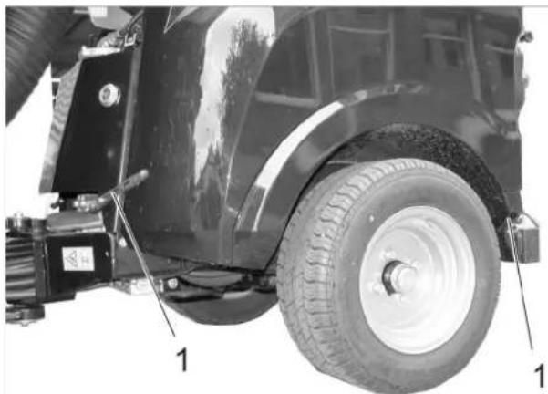
1 Cover lock
Open both hood latches.
Raise the panels and swivel them to the top and out.
Remove panels.
10.2.3 Install the engine's side panels
1 Fastening bushing
2 Centering cone
Thread the bottom end of the panel behind the wheel.
Swivel the panel up to the appliance and hook the top edge of the panel into the fastening bushing.
Close the hood latches.
10.2.4 Remove the radiator grill
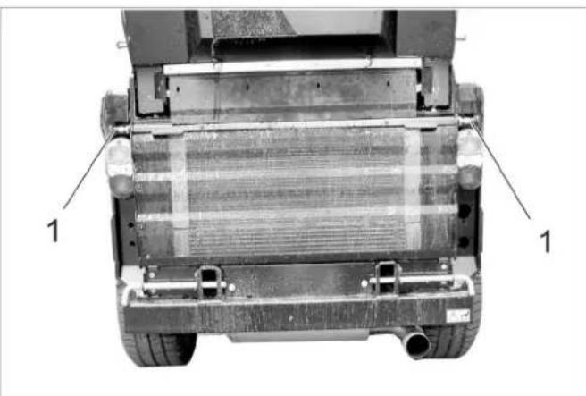
1 Lock
Open both latches (pull the latch out, rotate about 90^ and release).
Swivel the radiator grill toward the top, pull up and remove.
10.3 Cleaning
Raise the working machine.
Park the machine on an even surface.
Set engine speed to MIN position.
Turn ignition key to "STOP" and remove it.
Lockparkingbrake.
10.3.1 Cleaning the device
Clean appliance daily after finishing work.
CAUTION
Risk of damage!
Shaft seals, electrical components and hydraulic valves must not be cleaned using a high pressure water jet.
Do not rinse the engine with water.
When cleaning the appliance with a high pressure cleaner, adhere to the respective safety instructions.
Radiator fins must only be cleaned with compressed air (max. 5 bar), not with water.
Do not use aggressive cleaning agents.
In order to protect the air filter only wash the rear of the appliance while the motor is shut off.
Check the vehicle for oil and fuel leaks to prevent fires. Get customer service to fix the leaks.
Check front power lifter for ease of movement (raising and lowering).
To avoid fires, keep the engine, muffler, battery and fuel tank free of plant residue and oil.
Check the engine for contamination, clean with a brush or compressed air if required
10.3.2 Clean the radiator
Check the radiator for contamination.
Remove large object by hand.
Remove contamination with a soft brush or compressed air.
10.4 Maintenance intervals
NOTICE
In order to safeguard warranty claims, all service and maintenance work during the warranty period must be carried out by the authorised Kärcher Customer Service in accordance with the maintenance booklet.
NOTICE
The elapsed-time counter shows the timing of the maintenance intervals.
10.4.1 Daily before starting operations
Check the function of all operating elements and control lamps.
Refill the fuel tank.
Check engine oil level.
Check cooler water level.
Check the hydraulic oil level.
Check fuel filter.
Check the air filter, clean if required.
Grease all bearings that are marked with an "**" under "Maintenance tasks/vehicle".
Check whether taps on the water separator and the fuel filter are open.
Make sure that the water separator does not contain water.
Clean the cooler.
Check whether a rear weight is necessary when driving with attachments and whether it has been installed.
Check the entire appliance for damages.
10.4.2 After each vehicle wash
Grease all bearings that are marked with an ** under "Maintenance tasks/vehicle".
10.4.3 Weekly
Check the tyre condition and the tyre pressure. See the label in the driver cabin or the chapter "Technical Data | Tyres" for the recommended tyre pressure.
Check water level of wiper.
10.4.4 After the first 50 operating hours
Have the initial inspection performed by Customer Service.
10.4.5 Every 50 operating hours
Check and clean the radiator fan.
Check battery.
Check battery pole for oxidation; brush it if required and lubricate it using pole grease. Ensure that the connection cable sits firmly.
Clean the alternator (do not use the high-pressure cleaner).
Lubricate bearings (see section "Lubricate appliance").
10.4.6 Every 250 operating hours or every six months
Check bearing of the articulated steering. *
Change the engine oil and the oil filter.
Check mixing ratio of water/ anti-freezing agent.
Clean or replace the water filter.
Change the oil in the wheel motors.
Check for tightness, abrasion spots and tight seating of the hydraulic system and the connections.
Change the air filter.
Check the brakes for function and setting. *
Check the motor speed and the setting. *
Check hose from air filter to the motor.
Check hoses and clamps.
Clean the cooling fins of the water cooler, the oil cooler and the air conditioning system with compressed air.
Check the function of the heater and the heater fan. *
Check the air filter of the heater blower, replace if required.
Check V-Belt for wear and tear.
Check the smooth running of the Bowden cables and the moveable parts
Clean the ventilation slots of the lights.
- To be done by Customer Service.
10.4.7 Every 500 hours or twice a year
All work must be performed by customer service.
Replace the fuel filter.
Replace hydraulic oil.
Replace hydraulic oil filter.
Check the exhaust system for leaks.
Check current-carrying lines and contacts for damages and oxidation
Replace the V-belt of the hydraulic pump and grease the tension roller.
10.4.8 After 1000 operating hours or once a year
All work must be performed by customer service.
Replace cooling water.
Adjust the valves.
Perform a visual check of the fuel hoses and the coolant hoses, replace if necessary.
10.4.9 Every 1500 operating hours
All work must be performed by customer service.
Replace V-belt.
Check and clean the injector nozzles.
10.4.10 Every 2000 operating hours
Lap the inlet and outlet valve seats (by Customer Service).
10.4.11 Yearly
Safety inspection according to local regulations by customer service.
10.5 Maintenance Works
10.5.1 General notes on safety
△DANGER
Risk to life
When carrying out repairs, remove the vehicle from the danger zone of passing traffic and wear reflective clothing.
△DANGER
Risk of injury due to engine overrun. Once the engine has been switched off, wait for 5 seconds. Stay well clear of the working area for this time.
Risk of injury when vehicle accidentally starts up. Remove the ignition key and disconnect the battery prior to performing cleaning and maintenance tasks on the vehicle.
Be careful when using high-pressure cleaners for cleaning! Do not directly point the high-pressure jet to electrical components, tyres, radiator fins and hydraulic hoses.
When cleaning the appliance with a high pressure cleaner, adhere to the respective safety instructions.
Maintenance on the hydraulic system must only be carried out by trained personnel.
DANGER
Risk of injury!
Lower the attachment unit to relieve the hydraulic system of pressure during all maintenance work.
Risk of injury due to inadvertently lowering waste container. Prior to working underneath the waste container, move the waste container all the way into the emptying position. (for sweepers).
Risk of injury due to inadvertently lowering waste container. Only perform work on the turbine while the waste container is completely lifted (for sweepers).
WARNING
Allow the machine sufficient time to cool down before carrying out any maintenance and repair work.
Do not touch any hot parts, such as the drive motor and exhaust system.
Cooling water is hot.
CAUTION
Please do not release engine oil, fuel oil, diesel and petrol into the environment. Protect the ground and dispose of used oil in an environmentally-clean manner.
10.5.2 Preparation
Park the machine on an even surface.
Lower the working appliance.
Set engine speed to MIN position.
Turn ignition key to "STOP" and remove it.
Lockparking brake.
10.5.3 Safety notes regarding the batteries
Please observe the following warning notes when handling batteries:
| Observe information in the user manual of the battery and on the battery as well as in these operat-ing instructions! | Danger of causti-cization! | ||
| Wear an eye shield! | First aid! | ||
| Keep away children from acid and batter-ies! | Warning note! | ||
| Risk of explosion! Disposal | |||
| Fire, sparks, open light, and smoking not allowed! | Pb | Do not throw the battery in the dustbin! |
DANGER
Follow accident prevention regulations as well as DIN VDE 0510, VDE 0105 T.1.
Risk of explosion! Do not put tools or similar on the battery, i.e. on the terminal poles and cell connectors.
Risk of injury! Ensure that wounds never come into contact with lead. Always clean your hands after having worked with batteries.
Risk of fire and explosion!
Smoking and open flames must be strictly avoided.
- Rooms where batteries are charged must have good ventilation because highly explosive gas is emitted during charging.
Danger of causticization!
- Rinse thoroughly with lots of clear water if acid gets into the eye or comes in contact with the skin.
- Then consult a doctor immediately.
- Wash off the acid If it comes in contact with the clothes.
- Change clothing.
10.5.4 Installing and connecting the battery
Insert battery in battery mount.
Connect pole terminal (red cable) to positive pole (+) .
Connect pole terminal to negative pole (-).
Insert the battery.
Screw the holder to the battery bottom.
NOTICE
Prior to removing the battery, make sure that the negative pole lead is disconnected first. Check that the battery poles and pole terminals are adequately protected with pole grease.
10.5.5 Charging battery
Danger
Risk of injury! Comply with safety regulations on the handling of batteries. Observe the directions provided by the manufacturer of the charger.
Danger
Charge the battery only with an appropriate charger.
Remove the battery.
Clamp off the minus pole of the battery.
Disconnect the positive terminal of the battery.
Connect positive terminal cable from the charger to the positive pole connection on the battery.
Connect negative terminal cable from the charger to the negative pole connection on the battery.
Plug in mains connector and switch on charger.
Charge battery using lowest possible level of charging current.
NOTICE
When the battery is charged, first remove the charger from the mains and then disconnect it from the battery.
10.5.6 Replacing wheel
Danger
When carrying out repairs on public highways, wear warning clothing when working close to passing traffic.
△DANGER
Risk of injury!
Check stability of ground. Also secure the machine with wheel chock(s) to prevent it rolling away.
Park the machine on an even surface.
Remove ignition key.
Lockparkingbrake.
Position vehicle jack at the appropriate mounting point for the front or rear wheel.
NOTICE
Use a suitable commercially available vehicle jack.
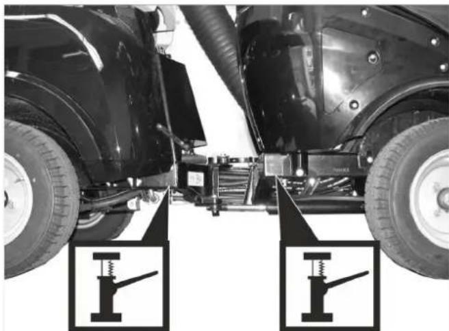
Intake points for the jack
Loosen the wheel nuts/wheel bolts by about 1 revolution using a suitable tool.
Raise machine using vehicle jack.
Unscrew the wheel nuts/wheel bolts and remove them.
Remove wheel.
Have the defective wheel repaired by a specialised repair shop.
Place the wheel and screw in the wheel nuts/wheel bolts all the way; tighten them lightly.
Lower machine using vehicle jack.
Torque the wheel nuts/wheel bolts to the required torque.
Tightening torque for front tyres 83 - 85 Nm
Tightening torque for rear tyres 83 - 85 Nm
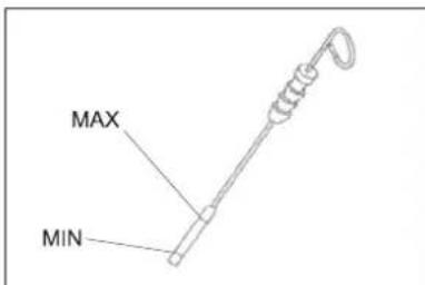
10.5.7 Check engine oil level and top up, if required
1 Oil cap (engine)
2 Oil dipstick
3 Oil filter
Park the machine on an even surface.
Pull out oil dipstick.
Wipe off oil dipstick and insert.
Pull out oil dipstick.
Read the value of the oil level.
Insert the oil dip again.
- The oil level must lie between "MIN" and "MAX" marking.
- Add motor oil if the oil level is below the "MIN" marking.
- Do not fill oil above the "MAX" marking.
Remove oil cap.
Fill in motor oil. Oil grade: Refer to chapter "Technical data"
Close oil cap.
Wait at least 5 minutes.
Check engine oil level.
CAUTION
An oil level that is too high leads to damages of the engine by overheating. If the oil level exceeds the "MAX" mark, oil must be drained until the correct oil fill level has been reached.
10.5.8 Change the motor oil and the oil filter
Note: A warm motor facilitates the draining process.
Danger
Risk of burns due to hot oil or possible hot hose lines!
Ready a catch bin for appr. 6 litre oil.
Allow engine to cool down.
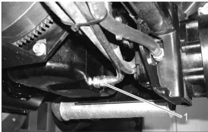
1 O i l d r a i n s c r e w
Unscrew oil drain plug.
Remove oil cap.
Drain off oil.
Unscrew the oil filter.
Clean the intake and sealing areas.
Coat the washer of the new oil filter with oil before fitting it.
Fit in the new oil filter and tighten it by hand.
Screw in the oil drain screw along with the new washer (torque to 60 Nm).
Fill in motor oil.
Oil grade: Refer to chapter "Technical data"
Close oil filler opening.
Let the motor run for approx. 30 seconds.
Check engine oil level.
Deliver the old oil to the respective collection centres.
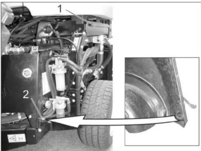
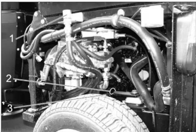
10.5.9 Check hydraulic oil level and refill hydraulic oil
Important
In order to avoid operational problems, utmost cleanliness is vital for all check and maintenance work.
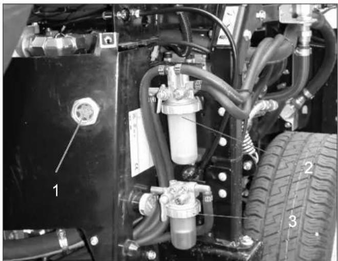
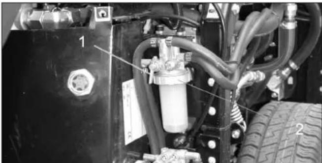
1 Sight glass hydraulic oil
2 Fuel filter
3 Water separator
The oil level must be within the viewing glass.
Refill hydraulic oil.
Oil grade: Refer to chapter "Technical data"
Note: Low hydraulic oil can only be topped up with a special optional accessory (order no.) or by the Kärcher after-sales service.
10.5.10 Replacing hydraulic oil and hydraulic oil filter
Replacement must be performed by the authorised customer service.
Even the finest contamination in the hydraulic system can cause severe faults; therefore, the system is fitted with a hydraulic oil filter.
10.5.11 Check hydraulic unit
Only Kärcher Customer Service is authorised to carry out maintenance tasks on the hydraulic unit.
Check all hydraulic hoses and connections and ensure that they are leak-proof.
10.5.12 Change the oil in the wheel motors
Replacement must be performed by the authorised customer service.
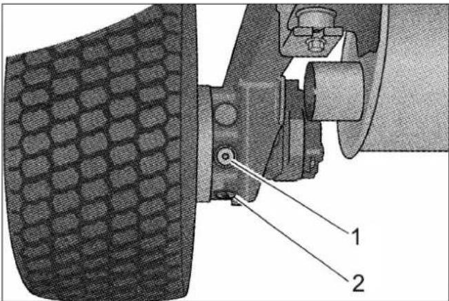
1 Oil fill screw
2 Oil drain screw
10.5.13 Check coolant level
Remove the right engine panel.

1 Coolant expansion tank
The cooling water level must be checked while the engine is cooled off.
- The cooling water level must be at the lower marking.
10.5.14 Refill cooling water
-
Use a water and antifreeze mixture to refill.
-
Do not mix different antifreeze types.
-
Use only soft water for the water and antifreeze mixture.
-
Only top up coolant when the engine is cool.
Remove the right engine panel.
If the cooling water reservoir is completely empty, first fill up the radiator:
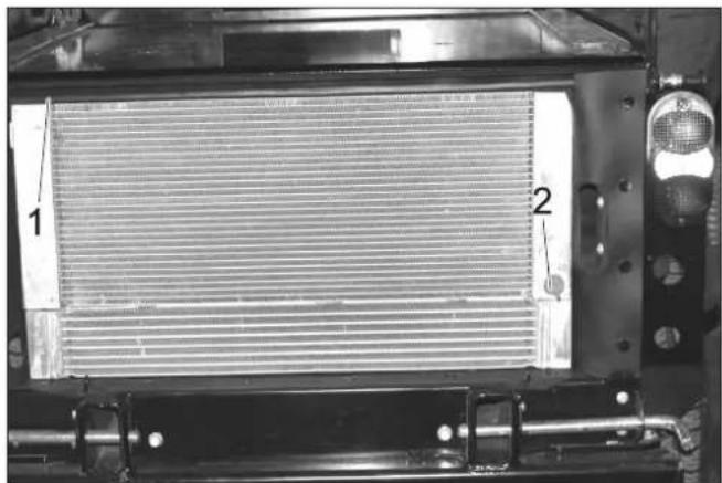
1 Radiator lid
2 Drain Screw
Unscrew the radiator cap.
Fill the radiator slowly all the way to the top without bubbles.
Screw on the radiator lid.
Fill the cooling water equalising reservoir:
Remove the lid of the equalising reservoir.
Fill the equalising reservoir to the bottom mark.
Close the lid for the equalising reservoir.
Start the engine and let it warm up.
Check the filling level in the coolant expansion tank. While the engine is warm, the cooling water level must be at the top mark.
If the cooling water level is too low, shut the engine off, let it cool off and fill the missing cooling water volume into the cooling water equalising reservoir.
10.5.15 Check the water separator
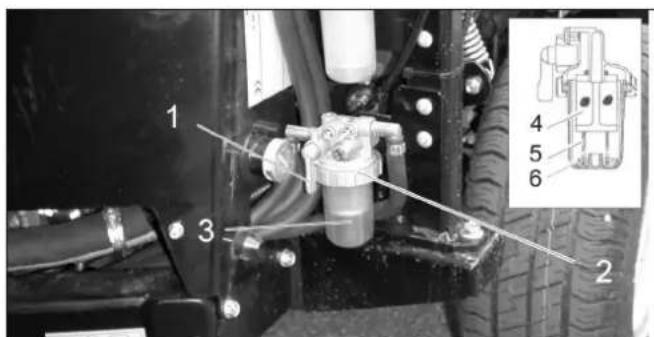
1 Locking tap
2 Union joint
3 Container
4 Wire filter
5 F I o a t
6 Spring
Ensure that the drain-off tap is open.
Check whether the floater is located on the bottom of the water separator.
If the floater is not on the bottom, there is water in the water separator and the water separator must be cleaned.
10.5.16 Clean the water separator
Danger
Risk of explosion!
- Do not carry out maintenance tasks in closed rooms.
Smoking and open flames must be strictly avoided.
Close the stop valve.
Place the collection trough under the water separator.
Loosen the union joint.
Remove the water separator reservoir.
Remove the spring and the floater from the reservoir.
Clean the interior of the reservoir.
Clean the wire filter.
Check the O-ring between the reservoir and the top part of the water separator.
Reassemble the water separator.
Open locking tap.
Deaerate the fuel system
10.5.17 Replace the fuel filter
1 Stop cock
2 Union joint
△WARNING
Risk of injury due to spilled fuel! Collect and wipe up spilled fuel immediately.
Wear safety gloves.
Switch off the engine and let it cool down.
Close the locking tap at the water separator.
Place the collection trough under the fuel filter.
Unscrew the fuel filter.
Apply a thin film of fuel to the seal of the new fuel filter.
Screw the new fuel filter in fingertight.
Open the locking tap at the water separator.
10.5.18 Bleed the fuel system
If the tank is empty or if the fuel filter was replaced, the fuel system must be bleed.
Check if the fuel tank is filled.
Open the locking tap at the water separator.
Start the motor.
Close the stop-cock when the system is bled.
10.5.19 Check the air filter

1 Change air filter indicator
If the ventilation display is red, the air filter insert must be replaced.
10.5.20 Cleaning and replacing the air filter
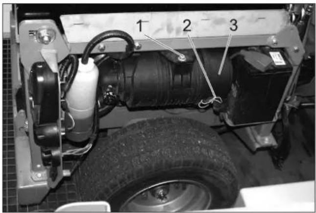
1 Screw
2 Clip
3 Air filter housing
Unscrew the screw.
Slide the air filter in and remove it toward the bottom.
Loosen the clamps.
Open the air filter housing.

1 Air filter insert
2 Pre-filter
3 Clip
Remove pre-filter.
Leave the air filter insert in place and thus prevent the dust from entering the engine when cleaning the prefilter.
Carefully blow out the prefilter from the inside to the outside with compressed air (0.3...0.5 MPa).
If the prefilter does not become clean or if the prefilter is damaged, use a new prefilter.
Clean the interior of the air filter reservoir.
Replace air filter insert if necessary.
Reassemble air filter in the reverse sequence.
Press the key of the air filter display to reset the display.
10.5.21 Lubricate the machine
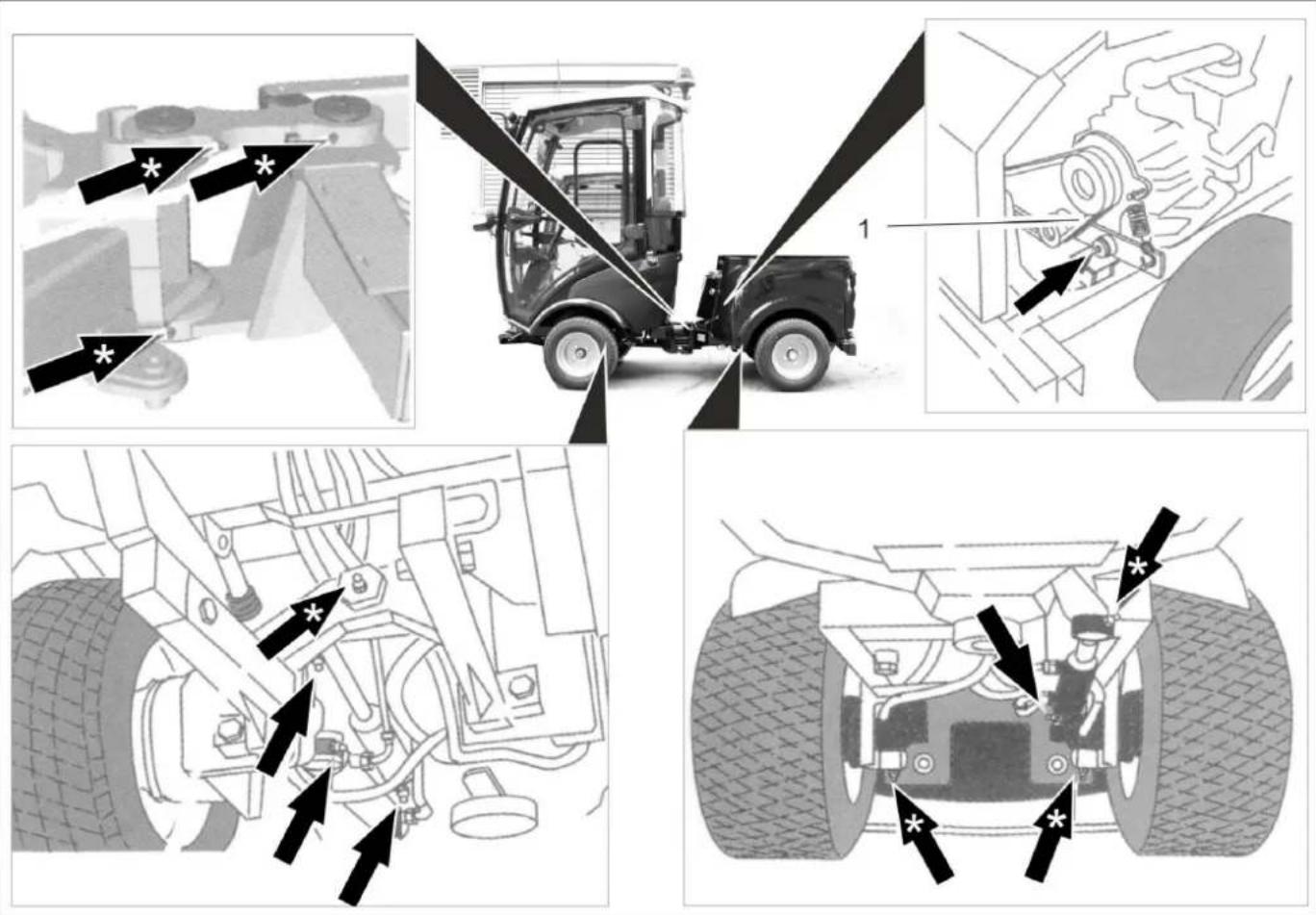
Illustration is symbolic
1 V - b e l t
CAUTION
Risk of functional disturbances. Do not let the V-belts get in contact with the grease.
Lubricate the grease nipples marked with an arrow with the grease gun.
Lubricate the grease nipples marked with ** arrows pri- or to starting work daily.
Carefully lubricate all moving parts, such as locking and safety levers, from time to time.
Use high quality multi-purpose grease and use grease gun to lubricate.
10.5.22 Checking the V-Belt
Check the V-belts on the radiator fan of the engine.
10.5.23 Maintaining the wiper
only device with driver cabin

1 Spray nozzle
2 Screw
Clean/ set the spray nozzles:
Clean the spray nozzle openings using a wire.
Adjust the spraying direction by turning the spray head with a wire.
Change the wiper blades:
Loosen the screw.
Change the wiper blade.
10.6 Fuses
NOTICE
Only use fuses with identical safety ratings.
Replace defective fuses.
10.6.1 Replacing the fuses in the fuse box in the driver cabin
only device with driver cabin
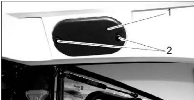
1 Cover
2 Knurled head screw
Unscrew the knurled screws and remove the cover.
| Fuses driver's cab | ||
| 1 Free | switch location in the ceiling panel (second location from the right) | 10 A |
| 2 Car radio connection 3 A | ||
| 3 Working light 10 A | ||
| 4 Switch for option (e.g. heated outside mirrors) | 10 A | |
| 5 Wiper 10 A | ||
| 6 Wind screen washer system 3 A | ||
| 7 Overall lamp 7.5 A | ||
| 8 Cabin lighting 3 A | ||
| 9 Relay high beam | ||
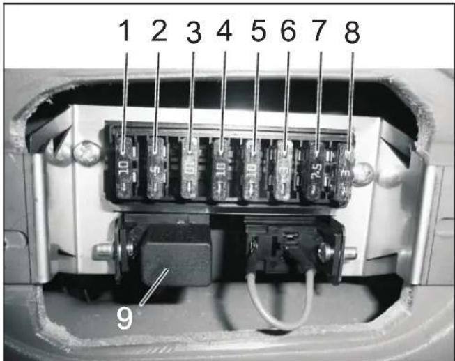
10.6.2 Replacing the fuses in the fuse box of the motor compartment
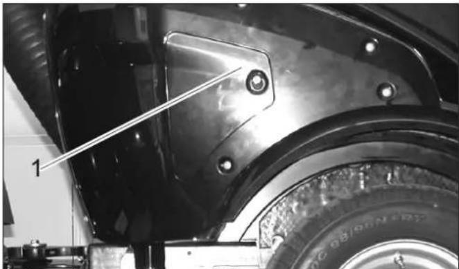
1 Cover
Remove the lid.
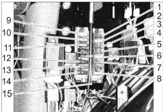
Fuses motor compartment
| 1 Indicator lamps, cooling water temperature buzzer, fuel pump, reverse horn, 7-way socket outlet front, 2-way socket outlet front, motor shutoff valve timer, motor shut-off valve (holding current) | 10 A | |
| 2 2-pin socket front, 7-pin socket front, 2-pin socket rear, front light | 20 A | |
| 3 Driving direction valve, generator, 10 A | ||
| 4 Air-conditioner 7.5 A | ||
| 5 Onboard socket panel, 7-pin socket front 10 A | ||
| 6 Motor shutoff valve (inrush current) 30 A | ||
| 7 Hour meter for sweeping operation, PTO Stop, indicator lamp brake | 10 A | |
| 8 Main fuse 40 A | ||
| 9 Dipped beam 20 A | ||
| 10 Air-conditioner | 20 A | |
| 11 Cabin | 30 A | |
| 12 Rotating beacon, horn, light relay, 7-way socket outlet front (pin 1) | 10 A | |
| 13 Blinker, hazard warning system | 10 A | |
| 14 Air-conditioner | 10 A | |
| 15 Comfort seat | 15 A | |
11 Troubleshooting
11.1 Faults with display
| Display Cause Remedy By whom | |||
| Warning lamp for motor temperature lights up | Engine is overheated Set the engine | ine speed to idle. Operator | |
| Check the level of cooling liquid in the engine. If the warning lamp does not turn off within 5 minutes, shut off the engine and contact Cus-tomer Service. | |||
| Warning lamp for hydraulic oil temperature | Hydraulic oil overheated | Temperature too high: Let the motor idle until the warning light is off. Switch off the working hydraulic. | Operator |
| Warning lamp for battery lights up | Battery is not being charged Call | Customer Service. Operator | |
11.2 Faults without display
| Fault Remedy | |
| Appliance cannot be started | Charging or replacing battery |
| Press the brake pedal. | |
| Fill in fuel,deaerate the fuel system | |
| Clean or replace fuel filter | |
| Check fuel pipes,connections and joints and maintain them if required | |
| Inform Kärcher Customer Service. | |
| Engine is running erratically | Clean or replace air filter |
| Check fuel pipes,connections and joints and maintain them if required | |
| Inform Kärcher Customer Service. | |
| Engine is running but machine is only moving slowly or is not moving at all | Release parking brake |
| Check level of hydraulic fuel | |
| Inform Kärcher Customer Service. | |
| Operation problems with hydraulic movement parts | Inform Kärcher Customer Service. |
11.3 Towing
CAUTION
Risk of damage!
The vehicle must not be towed away. Only slowly push or pull the device (walking speed)
△DANGER
The vehicle is not approved for crane loading.
Fasten the towing rope to the towing eye in the front or the rear.
→ Slowly drag the vehicle onto the transport vehicle.
12 Technical specifications
| MIC 26 | ||
| Drive speed, forward km/h 20 | ||
| Drive speed, reverse km/h 8 | ||
| Working speed km/h 10 | ||
| Climbing capability (max.) % 25 | ||
| Driven axles 2 | ||
| Usage duration when tank is full h about 12 | ||
| Engine | ||
| Manufacturer -- Yanmar | ||
| Type -- | 3TNV76-DU | |
| Cylinder capacity cm | 3 | 1116 |
| Engine output at 3000 rpm | kW | 18.9 |
| Torque at 2000 1/min Nm 66.6 | ||
| Electrical system | ||
| Battery | V, Ah | 12, 40 |
| Fuel | ||
| Fuel type | Diesel | |
| Fuel tank capacity | I | 37 |
| Engine oil type | SAE 10W-30 | |
| Engine oil volume | I | 5.1 |
| Coolant (SAE J814C) | -- Havoline | XLC Anti-freeze |
| Hydraulic oil type | Renol B HV 46 | |
| Hydraulic oil volume | I | 20 |
| Oil type of wheel motors | GL4/5 75-W90 | |
| Oil quantity, wheel motors | I | 4 x 0.08...0.09 |
| Greases | ||
| For points to be lubricated manually | -- Multi-purpose grease | |
| Working conditions | ||
| Temperature | °C | -5 ... +40 |
| Air humidity, non-condensing | % 0 - 90 | |
| Dimensions and weights | ||
| Length x width x height | mm | 2626 x 1084 x 1978 |
| Transport weight | kg | 870 - 944 |
| Permissible overall weight | kg | 1750 |
| Permissible front axle load | kg | 900 |
| Permissible rear axle load | kg | 1200 |
| Drawbar load of lorry hitch (Option) | kg | 120 |
| Drawing load of lorry hitch (Option), with/without brakes | kg | 1250/750 |
| Turning radius (inside) | mm | 780 |
| Resulting values as per EN 60335-2-72 | ||
| Vibration total value on arms | m/s2 | <2.5 |
| Uncertainty K | m/s2 | 0.2 |
| Vibration total value on seat area | m/s2 | <0.5 |
| Uncertainty K | m/s2 | 0.2 |
| Determined values in acc. with 2009/76/EU | ||
| Sound pressure level LpA | dB(A) | 77 |
12.1 Tyres
CAUTION
Only use Karcher-approved tyres.
| Tyre type Tyre size Recommended | tyre pressure MPa (bar) | |
| Road tyres 195/55 R10 | C 0.62 (6.2) | |
| Grass tyres 20x10.00-1 | 0 0.28 (2.8) | |
| Standard tyres, extra wide | 20x12.00-10 0.14 (1.4) | |
| Traction tyres (coarse tread) | 20x 8.00-10 0.45 (4.5) | |
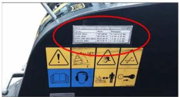
Figure: Label in the driver cabin with recommended tyre pressures
1 Table des matieres
2 Indications relatives au vehicule 2
2 Indications relatives au vehicule
12.1 Bandenuitrusting 36

8.13.5 Bediening 8.13.6 Werking joystick
△GEVAAR
Koelvloeistof is heet.
VOORZICHTIG
12.1 Bandenuitrusting
VOORZICHTIG
8.7.5 Ligar as luzes traseiras
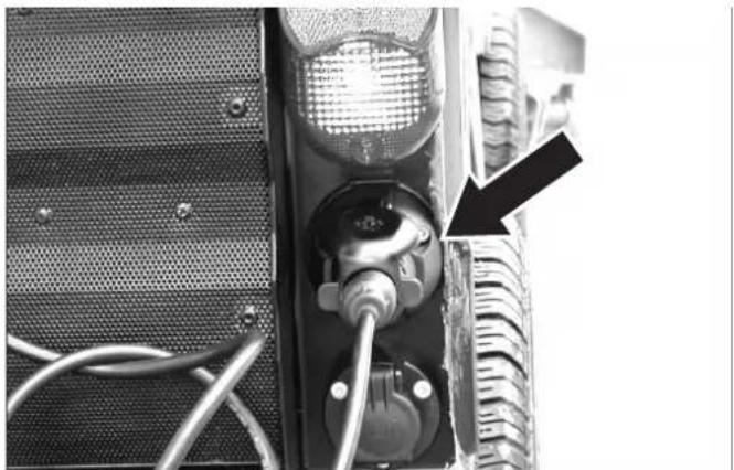
10.5.6 Mudar as rodas
Perigo
→ Fia evepytooinan tou diavopéa evepytoinote to PTO
8.7.7 Pounotheoi eitoupyiac
2 Bida ekpons laoiou
10.5.13 ELeyTe Tn OToaOu Tou yukTKoU uypou
ApaieoTe Tn 8eixia eTevouon kivtnpca.
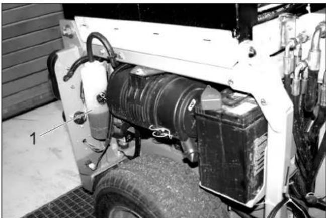
ELeyTe Tov TpaTeZoEiOn IaVtA OToV aepiotnpac yuyeiou Tou Kivntnpa.
10.5.23 Uvtnpnon uαλokαθapioTnpωv
Movo ouokevc kaipiva odyou
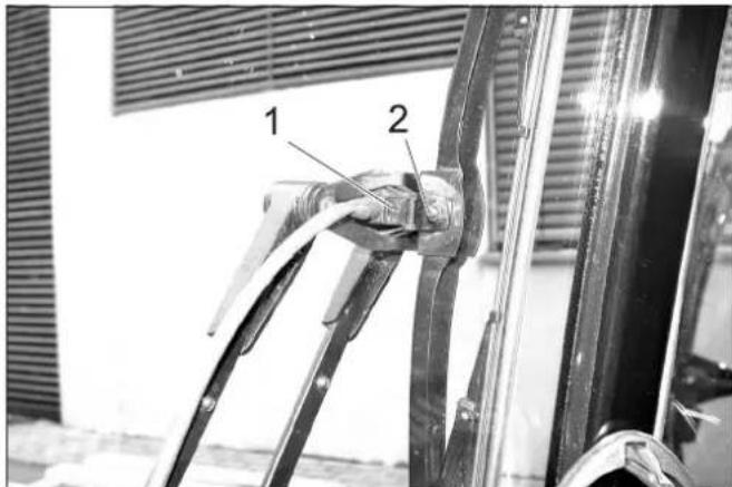
1 Akpoquo yekaoou
2Koxlaic
KaapioTe /puθmuTe Ta akpofoia Ψekaou:
Register your product and benefit from many advantages.
www.kaercher.com/welcome ★★★★★
Rate your product and tell us your opinion.
www.kaercher.com/dealersearch
Alfred Kärcher SE & Co. KG
Alfred-Karcher-Str.28-40
71364 Winnenden (Germany)
Tel.: +49 7195 14-0
Fax: +49 7195 14-2212