
CRONO 4G - Boiler Baxi - Free user manual and instructions
Find the device manual for free CRONO 4G Baxi in PDF.
| Product type | Gas train for boiler burner |
| Brand | Baxi |
| Model | CRONO 4G |
| Connection | Flanges DN65, DN80, DN100, DN125 |
| Length (L) | From 875.5 mm to 1384 mm depending on model |
| Inlet diameter (Ø1) | DN65 to DN125 |
| Outlet diameter (Ø2) | DN80 to DN125 |
| Gas inlet pressure | 15 - 120 mbar |
| Gas outlet pressure | 0 - 22 mbar (adjustable by spring) |
| Available springs | Neutral (0-22 mbar), Yellow (15-120 mbar), Red (100-250 mbar) |
| Safety devices | Minimum gas pressure switch, safety valve, leak check VPS504 or additional pressure switch |
| Filter | Present, replaceable annually |
| Adjustment valve | Yes, with pressure adjustment screw |
| Safety valve | Yes |
| Electrical connections | Via burner, electrical diagram supplied (Fig. 4) |
| Installation | On the left side of the burner, use liquid sealant |
| Maintenance | Annual check by qualified technician, filter replacement and leak verification |
| Compatibility | Baxi burners with VGD gas train |
Frequently Asked Questions - CRONO 4G Baxi
User questions about CRONO 4G Baxi
0 question about this device. Answer the ones you know or ask your own.
Ask a new question about this device
Download the instructions for your Boiler in PDF format for free! Find your manual CRONO 4G - Baxi and take your electronic device back in hand. On this page are published all the documents necessary for the use of your device. CRONO 4G by Baxi.
USER MANUAL CRONO 4G Baxi
Ramp gas
GB Gas trains
F Rampe gaz
Rampede gas
CODE-CODIGO MODELLO-MODELE-MODELO
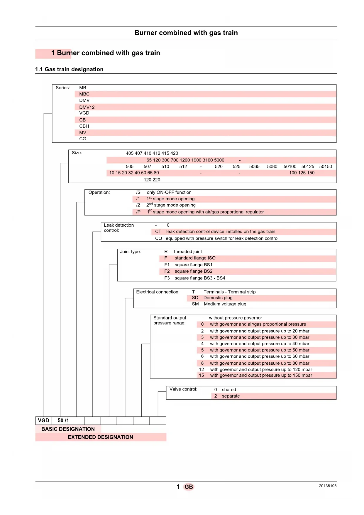
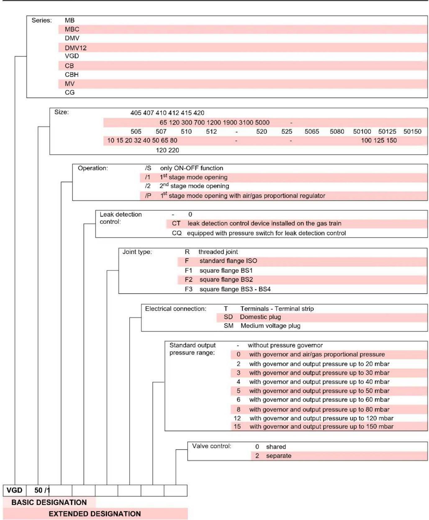
20137718-20169190 VGD 50/1 - VGD 50/1 CT
20140762-20169191 VGD 65/1 - VGD 65/1 CT
20140763-20169192 VGD 80/1 - VGD 80/1 CT
20169193-20169194 VGD 100/1 - VGD 100/1 CT
20169195-20169196 VGD 125/1 - VGD 125/1 CT
1 Burner combined with gas train
1.1 Gas train designation
2 Information and general warnings
2.1 Information about the instruction manual
2.1.1 Introduction
The instruction manual supplied with the gas train:
is an integral and essential part of the product and must not be separated from it; it must therefore be kept carefully for any necessary consultation and must accompany the gas train even if it is transferred to another owner or user, or to another system.
If the manual is lost or damaged, another copy must be requested from the Technical Assistance Service of the area;
is designed for use by qualified personnel;
offers important indications and instructions relating to the installation safety, start-up, use and maintenance of the gas train.
2.2 Guarantee and responsibility
The manufacturer guarantees its new products from the date of installation, in accordance with the regulations in force and/or the sales contract. Ensure, upon activating it for the first time, that the gas train is undamaged and complete.

Failure to observe the information given in this manual, operating negligence, incorrect installation and carrying out of non authorised modifications will result in the annulment by the manufacturer of the guarantee that it supplies with the gas train.
In particular, the rights to the guarantee and the responsibility will no longer be valid, in the event of damage to things or injury to people, if such damage/injury was due to any of the following causes:
incorrect installation, start-up, use and maintenance of the gas train;
improper, incorrect or unreasonable use of the gas train;
intervention of unqualified personnel;
carrying out of unauthorised modifications on the equipment;
use of the gas train with safety devices that are faulty, incorrectly applied and/or not working;
installation of untested supplementary components on the gas train;
supplying the gas train with inappropriate fuel;
faults in the fuel supply system;
continuation of use of the gas train when a fault has occurred;
repairs and/or overhauls incorrectly carried out;
modification of the combustion chamber with inserts that prevent the regular development of the structurally established flame;
insufficient and inappropriate surveillance and care of those gas train components most likely to be subject to wear and tear;
use of non-original components, including spare parts, kits, accessories and optional;
force majeure.
The manufacturer furthermore declines any and every responsibility for the failure to observe the contents of this manual.
3 Safety and prevention
3.1 Introduction
It is necessary, however, to bear in mind that the imprudent and clumsy use of the gas train may lead to situations of death risk for the user or third parties, as well as the damaging of the burner or other items. Inattention, thoughtlessness and excessive confidence often cause accidents; the same applies to tiredness and sleepiness.
It is a good idea to remember the following:
the gas train must only be used as expressly described. Any other use should be considered improper and therefore dangerous.
Modification of the gas train to alter its performance and destinations is not allowed.
The gas train must be used in impeccably secure conditions. Any disturbances that could compromise safety must be quickly eliminated.
It is not permissible to open or handle the components of the gas train, with the exclusive exception of parts necessary to maintenance.
Only those parts envisaged by the manufacturer can be replaced.

The manufacturer only guarantees the security of operations if all components of the gas train are undamaged and correctly positioned.
3.2 Personnel training
The user is the person, the body or the company that has purchased the gas train and that intends to use it for the purposes for which it was designed. They are responsible for the gas train and for training those who will operate it.
The user:
undertakes to entrust the gas train only to personnel who are qualified and trained to use it;
undertakes to inform his personnel in a suitable way about the application and observance of the safety instructions. With that aim, he undertakes to ensure that everyone knows the use and safety instructions for his own duties;
Personnel must follow all the danger and caution indications shown on the gas train.
Personnel must not carry out, on their own initiative, operations or interventions that are not within their province.
Personnel are obliged to inform their superiors of every problem or dangerous situation that may arise.
The assembly of parts of other makes, or any modifications, can alter the characteristics of the machine and hence compromise operating safety. The manufacturing company therefore accepts no responsibility whatsoever for any which may result from the use of non-original parts.
In addition:

must take all the measures necessary to prevent unauthorised people gaining access to the gas train;
the user must inform the manufacturer if faults or malfunctioning of the accident prevention systems are noticed, along with any presumed danger situation;
personnel must always use the personal protective equipment envisaged by legislation and follow the indications given in this manual.
Installation
| 4 | I | n | s | t | a | I | I | a | t | i | o | n |
4.1 Notes on safety for the installation
After carefully cleaning all around the area where the train will be installed, and arranging the correct lighting of the environment, proceed with the installation operations.

All the installation, maintenance and disassembly operations must be carried out with the electricity supply disconnected.

Train installation must be carried out by qualified personnel, as indicated in this manual and in compliance with the standards and regulations of the laws in force.
4.2 Handling

The handling operations for the train can be highly dangerous if not carried out with the greatest attention: keep any unauthorised people at a distance; check the integrity and suitability of the available means of handling.
Check also that the area in which you are working is empty and that there is an adequate escape area (i.e. a free, safe area to which you can quickly move if the train should fall).

Before proceeding with the installation operations, carefully clean all around the area where the train will be installed.
4.3 Preliminary checks
Checking the consignment

After removing all the packaging, check the integrity of the contents. If in doubt, do not use the gas train; contact the supplier.

The packaging elements (cardboard box, nails, clips, plastic bags, etc.) must not be abandoned as they are potential sources of danger and pollution; they should be collected and disposed of in the appropriate places.
4.4 Description
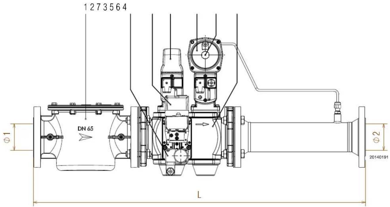
Fig. 1
1 F i l t e r
2 Minimum gas pressure switch
3 Safety valve
4 Valve body
5 Adjusting valve
6 Screw for gas pressure adjustment
7 Leak detection control (if present)
4.5 Gas train compatibility and leak detection control device
Leak detection control through VPS504 device
| Gas train | Code per 50Hz operational | Code per 60Hz operational |
| VGD 50/1 3010123 + 20186306 20050030 + 20186306 | ||
| VGD 65/1 - 80/1 - 100/1 - 125/1 | 3010123 (*) | 20050030 |

WARNING
(*) Kit code 3010123 (50 Hz) already included in VGD gas trains with codes 20169190, 20169191, 20169192, 20169194, 20169196.
Leak detection control through additional pressure switch
| Gas train | Kit code SIEMENS control box | Kit code LAMTEC control box |
| VGD 50/1 | 3010344 + 20185515 (**) | 20131430 + 20185515 (**) |
| VGD 65/1 - 80/1 - 100/1 - 125/1 | 3010344 | 20131430 |

WARNING
(^**) Code 20185515 always needed in case of leak detection control for VGD 50/1 gas train.
4.6 Gas train installation

Check that there are no gas leaks.

Pay attention when handling the train: danger of crushing of limbs.

Explosion danger due to fuel leaks in the presence of a flammable source.
Precautions: avoid knocking, attrition, sparks and heat.
Make sure that the fuel interception tap is closed before performing any operation.

The operator must use the required equipment during installation.

To avoid excess strain it is advisable to support bigger trains using an appropriate support.

The gas train is set to be installed on the left side of the burner.
Once unpacked, install the gas train as follows:
- Assemble the gas train using the screws supplied.
- Once connected, check the atmospheric seal of tubing. Use leak finder spray on the suspect spot only.
After assembly, check the train for leaks and make sure it is operating properly.
Tab. A
| Ø1 | Ø2 | L | P in | P out * | Spring ** |
| G2" | G2" | 875,5 | < 500 mbar | 15 - 120 mbar | 0 - 22 |
| DN 65 | DN 80 | 1013 | < 500 mbar | 15 - 120 mbar | 0 - 22 |
| DN 80 | DN 80 | 1036 | < 500 mbar | 15 - 120 mbar | 0 - 22 |
| DN 100 | DN 100 | 1329 | < 500 mbar | 15 - 120 mbar | 0 - 22 |
| DN 125 | DN 125 | 1384 | < 500 mbar | 15 - 120 mbar | 0 - 22 |
- Spring mounted in factory
** Supplied spring
For possible replacement see "Adjusting the pressure stabiliser" on page 7.
It may be necessary to place an adapter between the gas train and the burner (see the burner manual) if the diameters of the train are different from those for which the burner is set up.
To avoid excessive stress, you are advised to sustain larger trains with a suitable support.
4.6.1 Minimum gas pressure switch adjustment
Adjust the low gas pressure switch (Fig. 3) after carrying out all the other adjustments of the burner with the gas pressure switch adjusted at the beginning of the scale.
Let the burner work at the required output. Close slowly the gate valve until the pressure, measured on the gas pressure switch gauge, comes down of 5-6 mbar with regard to the working value.
Rotate slowly the gas pressure switch handle until the operation of the same gas pressure switch and the resultant burner shutdown. Open completely the gate valve.
4.6.2 Adjusting the pressure stabiliser
Loosen the protection (Fig. 3) and rotate the screw underneath: tighten it to increase the output pressure, or loosen it to reduce the pressure.
The pressure stabiliser is more effective when the pressure loss p between its input and output is greater; it also has more effect when the pressure downstream increases (an increase obtainable - bearing in mind the other operational needs and the mains pressure availability - by limiting the opening of the valves downstream).
The gas train outlet pressure depends on the spring installed under the adjustment screw (Fig. 3).
The gas train leaves the factory with the yellow spring as indicated in Tab. B.
In supplied of the flanged gas trains (DN65-80-100-125) there is a neutral spring (0÷ 22 mbar).
Springs can be ordered separately:
Tab. B
| Code Model | pG (mbar) | Color | |
| 20181839 A | GA29 0 - 22 Neutral | ||
| 20141900 A | GA22 15 - 120 Yellow | ||
| 20141901 A | GA23 100 - 250 Red | ||
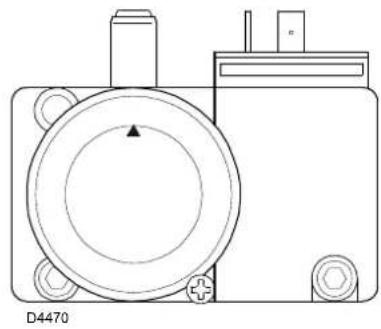
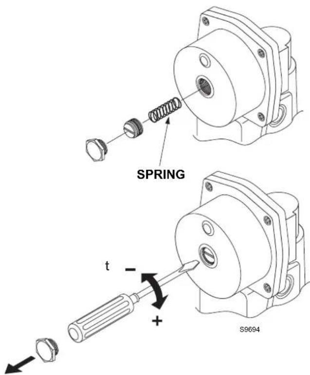
Fig. 2
Fig. 3
4.7 Electrical wiring
Notes on safety for the electrical wiring
The electrical wiring must be carried out with the electrical supply disconnected.
Electrical wiring must be carried out by qualified personnel and in compliance with the regulations currently in force in the country of destination. The manufacturer declines all responsibility for modifications or connections different from those shown in the wiring diagrams.
Check that the electrical supply of the train corresponds to that shown on the identification label and in this manual.
The electrical safety of the device is obtained only when it is correctly connected to an efficient earthing system, made according to current standards. It is necessary to check this fundamental safety requirement. In the event of doubt, have the electrical system checked by qualified personnel. Do not use the gas tubes as an earthing system for electrical devices.
Do not touch the device with wet or damp body parts and/or in bare feet. Do not pull the electric cables.
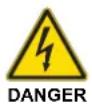
4.7.1 Electrical wiring
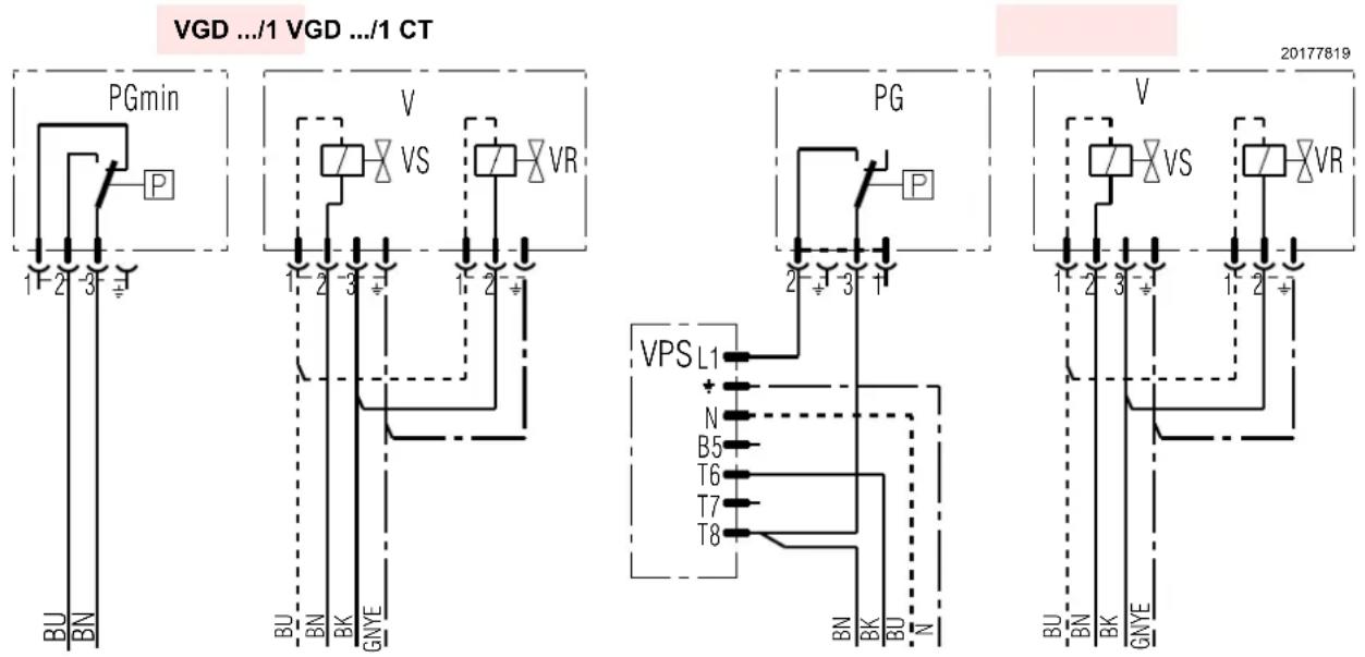
Fig. 4
Key (Fig. 4)
PG Minimum gas pressure
VPS Valve leak detection control device
VR Adjustment valve
VS Safety valves

For the electrical wirings to the burner, refer to the burner instruction manual.
5 Activation, calibration and functioning
5.1 Notes on safety for the first start-up

The first start-up of the burner must be carried out by qualified personnel, as indicated in this manual and in compliance with the standards and regulations of the laws in force.

Check the correct working of the adjustment, command and safety devices.
5.2 Pressure loss
The minimum necessary pressure in the network can be obtained by adding the pressure of the diagram to the burner pressure losses (see the burner technical instruction) and the back pressure of the combustion chamber (see the technical instruction of the heat generator).
Fig. 5
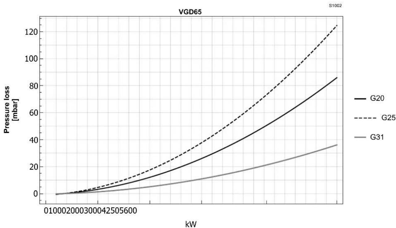
Fig. 6
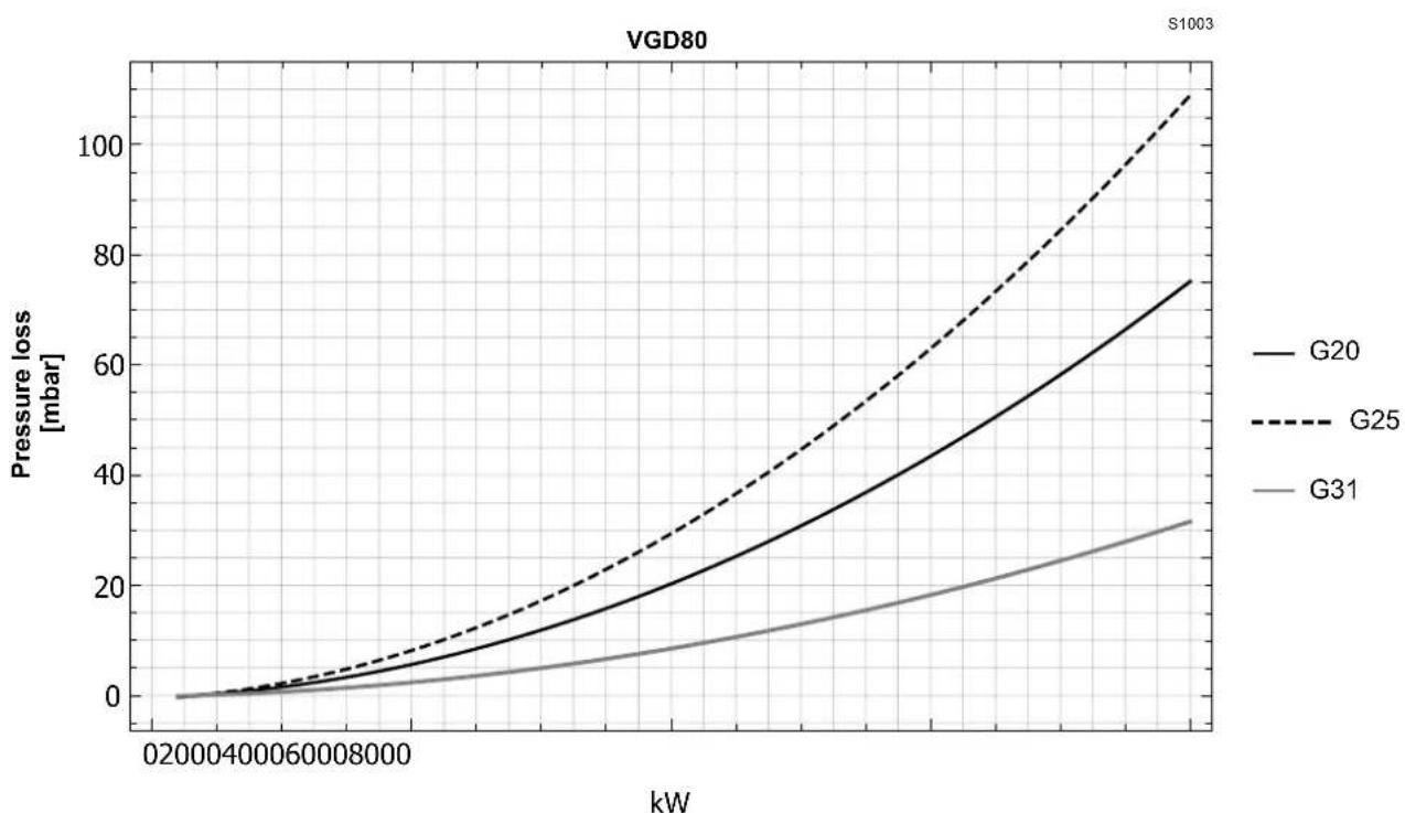
Fig. 7
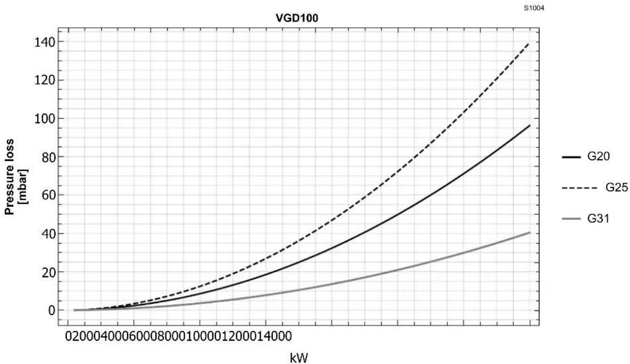
Fig. 8
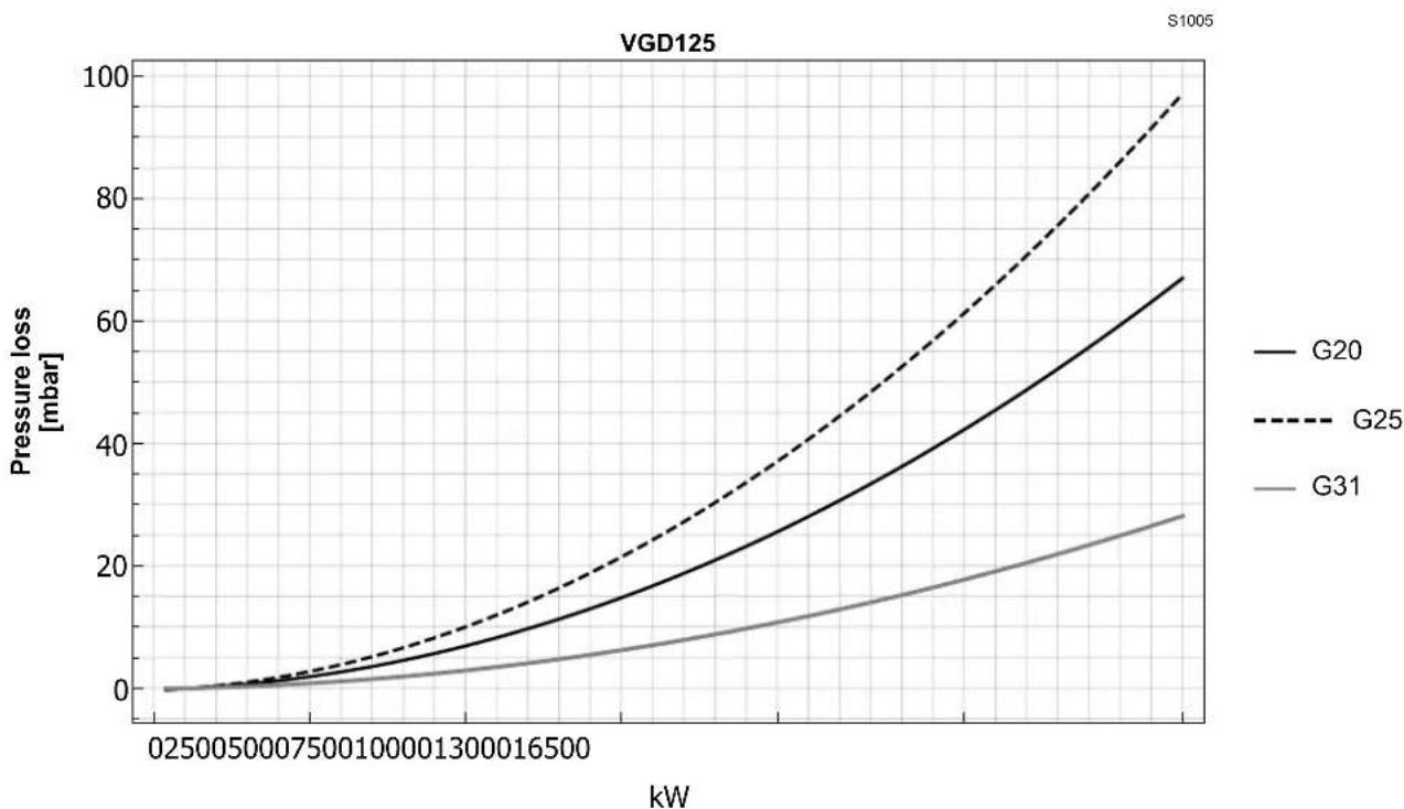
Fig. 9
6 Maintenance
6.1 Notes on safety for the maintenance
The periodic maintenance is essential for the good operation, safety, yield and duration of the gas train.
It allows you to reduce consumption and polluting emissions and to keep the product in a reliable state over time.

The maintenance interventions and the calibration must only be carried out by qualified, authorised personnel, in accordance with the contents of this manual and in compliance with the standards and regulations of current laws.
Before carrying out any maintenance, cleaning or checking operations:

Disconnect the electrical power using the main switch.

Close the fuel interception tap.

Wait for the components in contact with heat sources to cool down completely.
6.2 Maintenance programme
6.2.1 Maintenance frequency

The gas combustion system should be checked at least once a year by a representative of the manufacturer or another specialised technician.
6.2.2 Checking and cleaning

The operator must use the required equipment during maintenance.
6.2.3 Filter maintenance
The filtering element can be replaced by removing the upper cover of the filter (after loosening the screws that fix it in place).

You are advised to carry out a periodic check to see how clean it is and, in any case, replace it at least once a year.
Where the filter is being replaced regularly it is advisable to replace the fixing screws.
| 4 | I | n | s | t | a | I | I | a | t | i | o | n |