
LSPM1012C - Media player LG - Free user manual and instructions
Find the device manual for free LSPM1012C LG in PDF.
| Product Type | B/W Quad Surveillance System with 12" CRT Monitor and Cameras |
| Brand | LG |
| Model | LSPM1012C |
| Picture Tube | 12" CRT diagonal, 90° deflection |
| Monitor Resolution | 750 TV lines at center |
| Video Input | Composite video 1.0 Vp-p, 75 ohms |
| Video Output | Composite video 1.0 Vp-p |
| Number of Cameras | 4 (6-pin RJ-11 connectors) |
| Standard Camera Type | LVC-CY100NE/NC: 1/3" B/W CCD, 3.7 mm lens, 380 TV lines |
| Motion Detection Camera Type | LVC-CS100NE/NC: B/W CCD with PIR sensor |
| Monitor Power Supply | AC 230V, 50 Hz (European model) |
| Monitor Power Consumption | 38 W with camera |
| Monitor Dimensions | 297 x 290 x 285 mm (W x H x D) |
| Monitor Weight | Approximately 7.5 kg |
| Operating Temperature | -10°C to 50°C |
| Display Functions | Quad, Auto (Sequential), Manual, Small and Large PIP |
| Motion Detection | Yes, with sensitivity and zone adjustment |
| Alarm | External sensor inputs, open collector alarm output, adjustable duration |
| Audio | Built-in microphone on camera, speaker on monitor, intercom (Talk) function |
| Camera Mounting | Wall/ceiling bracket for standard camera; wall/corner mount for PIR camera |
| Cleaning | Disconnect before cleaning, use a dry or slightly damp cloth |
| General Information | Manual available in multiple languages, 181 pages |
Frequently Asked Questions - LSPM1012C LG
User questions about LSPM1012C LG
0 question about this device. Answer the ones you know or ask your own.
Ask a new question about this device
Download the instructions for your Media player in PDF format for free! Find your manual LSPM1012C - LG and take your electronic device back in hand. On this page are published all the documents necessary for the use of your device. LSPM1012C by LG.
USER MANUAL LSPM1012C LG
Before connecting, operating or adjusting this product, please read this instruction booklet carefully and completely.

RISK OF ELECTRIC SHOCK DO NOT OPEN

CAUTION: TO REDUCE THE RISK OF ELECTRIC SHOCK, DO NOT REMOVE COVER (OR BACK) NO USER SERVICEABLE PARTS INSIDE. REFER SERVICING TO QUALIFIED SERVICE PERSONNEL.
Graphic Symbol Explanation
The lightning flash with arrowhead symbol, within an equilateral triangle, is intended to alert the user to the presence of uninsulated 'dangerous voltage' within the product's enclosure that may be of sufficient magnitude to constitute a risk of electric shock to persons.
The exclamation point within an equilateral triangle is intended to alert the user to the presence of important operating and maintenance (servicing) instructions in the literature accompanying the appliance.


This product is manufactured to comply with the radio interference requirements of EEC DIRECTIVE 89/336/EEC, 93/68/EEC and 73/23/EEC.
THIS DEVICE COMPLIES WITH PART 15 OF THE FCC RULES. OPERATION IS SUBJECT TO THE FOLLOWING TWO CONDITIONS: (1) THIS DEVICE MAY NOT CAUSE HARMFUL INTERFERENCE, AND (2) THIS DEVICE MUST ACCEPT ANY INTERFERENCE RECEIVED, INCLUDING INTERFERENCE THAT MAY CAUSE UNDESIRED OPERATION.
This equipment has been tested and found to comply with the limits for a Class A digital device, pursuant to part 15 of the FCC Rules. These limits are designed to provide reasonable protection against harmful commercial environment. This equipment generates, uses, and can radiate radio frequency energy and, if not installed and used in accordance with the instruction manual, may cause harmful interference to radio communications. Operation of this equipment in a residential area is likely to cause harmful interference in which case the user will be required to correct the interference at his own expense.
Warning
TO PREVENT FIRE OR SHOCK HAZARDS, DO NOT EXPOSE THIS PRODUCT TO RAIN OR MOISTURE. Apparatus shall not be exposed to dripping or splashing and no object filled with liquids, such as vases, shall be placed on the apparatus. Wiring methods shall be in accordance with the National Electric Code, ANSI/NFPA 70.
IMPORTANT SAFETY INSTRUCTIONS
CAUTION: PLEASE READ AND OBSERVE ALL WARNINGS AND INSTRUCTIONS IN THIS OWNER'S MANUAL. AND THOSE MARKED ON THE PRODUCT. RETAIN THIS BOOKLET FOR FUTURE REFERENCE.
This product has been designed and manufactured to assure personal safety. Improper use can result in electric shock or fire hazard. The safeguards incorporated in this product will protect you if you observe the following procedures for installation, use, and servicing.
This product does not contain any parts that can be repaired by the user.
DO NOT REMOVE THE CABINET COVER, OR YOU MAY BE EXPOSED TO DANGEROUS VOLTAGE. REFER SERVICING TO QUALIFIED SERVICE PERSONNEL ONLY.
-
Read these instructions. -All these safety and operating instructions should be read before the product is operated.
-
Keep these instructions. -The safety, operating and use instructions should be retained for future reference.
-
Heed all warnings. -All warnings on the product and in the operating instructions should be adhered to.
-
Follow all instructions. -All operating and use instructions should be followed.
-
Do not use this product near water. -For example: near a bath tub, wash bowl, kitchen sink, laundry tub, in a wet basement; or near a swimming pool; and other areas located near water.
-
Clean only with dry cloth. -Unplugs this product from the wall outlet before cleaning. Do not use liquid cleaners.
-
Do not block any ventilation openings. Install in accordance with the manufacturer's instructions.-Slots and openings in the cabinet are provided for ventilation and to ensure reliable operation of the product and to protect it from over-heating. The openings should never be blocked by placing the product on a bed, sofa, rug or other similar surface. This product should not be placed in a built-in installation such as a bookcase or rack unless proper ventilation is provided or the manufacturer's instructions have been adhered to.
-
Do not install near any heat sources such as radiators, heat registers, stoves, or other apparatus (including amplifiers) that produce heat.
FCC Warning
This equipment may generate or use radio frequency energy. Changes or modifications to this equipment may cause harmful interference unless the modifications are expressly approved in the instruction manual. The user could lose the authority to operate this equipment if an unauthorized change or modification is made.
-
Do not defeat the safety purpose of the polarized or grounding-type plug. A polarized plug has two blades with one wider than the other. A grounding type plug has two blades and a third grounding prong. The wide blade or the third prong are provided for your safety. If the provided plug does not fit into your outlet, consult an electrician for replacement of the obsolete outlet.
-
Protect the power cord from being walked on or pinched particularly at plugs, convenience receptacles, and the point where they exit from the product.
-
Only use attachments/ accessories specified by the manufacturer.

-
Use only with the cart, stand, tripod, bracket, or table specified by the manufacturer, or sold with the apparatus. When a cart is used, use caution when moving the cart/product combination to avoid injury from tip-over.
-
Unplug this product during lightning storms or when unused for long periods of time.
-
Refer all servicing to qualified service personnel. Servicing is required when the product has been damaged in any way, such as when the power-supply cord or plug is damaged, liquid has been spilled or objects have fallen into the product, the product has been exposed to rain or moisture, does not operate normally, or has been dropped.
CE Warning
This is a Class A product. In a domestic environment this may cause radio interference in which case the user may be required to take adequate measures.
The apparatus shall not be exposed to dripping or splashing and no objects filled with liquids, such as vases, shall be placed on the apparatus.

INTRODUCTION
IMPORTANT SAFEGUARDS....5-6
Checking Product Contents....7
Part Names and Functions....8-12
Standard Camera 8
Motion Sensing Camera....9
Monitor Front 10-11
Monitor Rear....12
INSTALLATION
Individual Component Installation 13-19
Basic System Installation 20
Connecting Peripheral Devices 21
Connecting a PIR Motion Sensor....21
Connecting a VCR....21
HOW TO USE
OSD and Setup Menu 22-27
Explanation of Screen Display 22
OSD and Setup Menu....23-25
How to Use....26-27
REFERENCE
Specifications 28-30
Caution
The power source is located at the rear of the set. It contains high-voltage parts. If you remove the cover, it may cause fire or electric shock. Do not remove the cover by yourself. (Control switches are at the front of the monitor).
1. Read Instructions
All the safety and operating instructions should be read before the appliance is operated.
2. Retain Instructions
The safety and operating instructions should be retained for future reference.
3. Heed Warnings
All warnings on the monitor and in the operating instructions should be adhered to.
4. Follow Instructions
All operating and use instructions should be followed.
5. Cleaning
Unplug this monitor from the wall outlet before cleaning. Do not use liquid cleaners or aerosol cleaners. Use a damp cloth for cleaning.
Exception.
A monitor that is meant for uninterrupted service and that for some specific reason, such as the possibility of the loss of an authorization code for a CATV converter, is not intended to be unplugged by the user for cleaning or any other purpose, may exclude the reference to unplugging the monitor in the cleaning description otherwise required in Item 5.
6. Attachments
Do not use attachments not recommended by LG they may cause hazards.
7. Water and Moisture
Do not use this monitor near water for example, near a bathtub, wash bowl, kitchen sink, or laundry tub, in a wet basement, or a swimming pool and the like.
8. Accessories
Do not place this monitor on an unstable cart, stand, tripod, bracket, or table. The monitor may fall, causing serious injury to a child or adult, and serious damage to the appliance. Use only with a cart, stand, tripod, bracket, or table recommended by LG, or sold with the monitor. Any mounting of the monitor should follow LG's instructions, and should use a mounting accessory recommended by LG.
9. Ventilation
Slots and openings in the cabinet are provided for ventilation and to ensure reliable operation of the monitor and to protect it from overheating, and these openings should never be blocked by placing the monitor on a bed, sofa, rug, or other similar surface. This monitor should never be placed near or over a radiator or heat register. This monitor should not be placed in a built-in installation such as a bookcase or rack unless proper ventilation is provided or LG's instructions have been adhered to.
10. Power Sources
This monitor should be operated only from the type of power source indicated on the making label. If you are not sure of the type of power supply to your installation site, consult your LG dealer or local power company.
11. Grounding or Polarization
For monitors equipped with a 3-wire grounding-type plug that have a third(grounding)pin. This plug will only fit into a grounding type power outlet. This is a safety feature. If you are unable to insert the plug into the outlet, contact your electrician to replace your obsolete outlet. Do not defeat the safety purpose of the grounding-type plug.
12. Power
Cord Protection-Power supply cords should be routed so that they are not likely to be walked on or pinched by items placed upon or against them, paying particular attention to cords at plugs, convenience receptacles, and the point where they exit from the monitor.
13. Lightning
For added protection for this monitor during a lightning storm, or when it is left unattended and unused for long periods of time, unplug it from the wall outlet and disconnect the cable system. This will prevent damage to the monitor due to lightning and power-line surges.
14. Overloading
Do not overload wall outlets and extension cords as this can result in a risk of fire or electric shock.
15. Object and Liquid Entry
Never push objects of any kind into this monitor through openings as they may touch dangerous voltage points or short-out parts that could result in a fire or electric shock. Never spill liquids of any kind on the monitor.
16. Servicing
Do not attempt to service this monitor yourself as opening or removing covers may expose you to dangerous voltage or other hazards. Refer all servicing to qualified service personnel.
17. Damage Requiring Service
Unplug this monitor from the wall outlet and refer servicing to qualified service personnel under the following conditions.
a. When the power-supply cord or plug is damaged.
b. If liquid has been spilled, or objects have fallen into the monitor.
c. If the monitor has been exposed to rain or water.
d. If the monitor does not operate normally by following the operating instructions. Adjust only those controls that are covered by the operating instructions as an improper adjustment of other controls may result in damage and will often require extensive work by a qualified technician to restore the monitor to its normal operation.
e. If the monitor has been dropped or the cabinet has been damaged.
f. When the monitor exhibits a distinct change in performance.- this indicates a need for service.
18. Replacement Parts
When replacement parts are required, be sure the service technician has used replacement parts specified by LG or have the same characteristics as the original parts. Unauthorized substitutions may result in fire, electric shock or other hazards.
19. Safety Check
Upon completion of any service or repairs to this monitor, ask the service technician to perform safety checks to determine that the monitor is in proper operating condition.
After unpacking the product, check all following contents are enclosed with the product. Actual product may differ from the pictures.
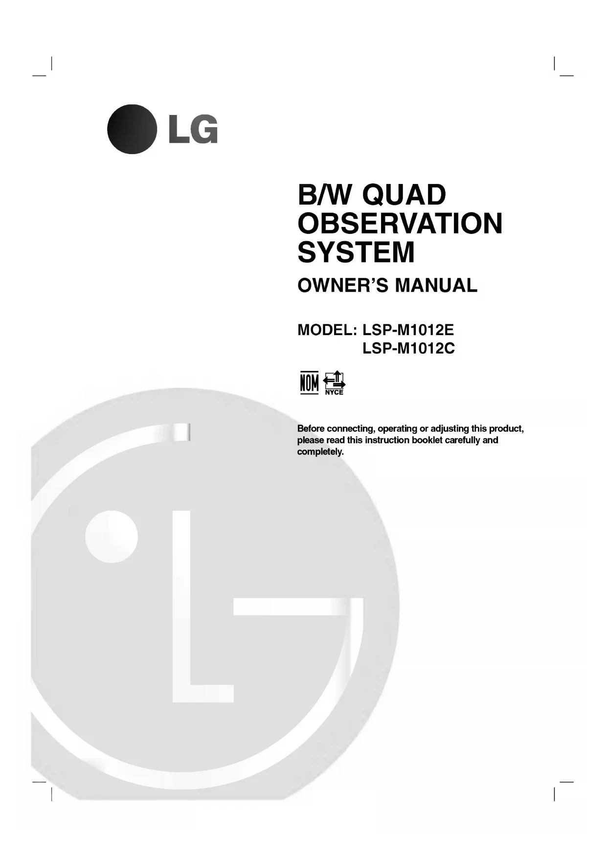
natural_image
Line drawing of a flat-screen CRT television unit (no text or symbols)MONITOR

natural_image
Line drawing of a rectangular electronic device with a circular lens on top (no text or symbols)STANDARD CAMERA

natural_image
Line drawing of a cylindrical device with a lid and handle (no text or symbols)MOTION SENSING CAMERA
- This camera is not supplied.
(Sold separately)
natural_image
Illustration of a coiled cable with connectors and a strap (no text or symbols)CAMERA CABLE (60ft: 1EA)

ALARM TERMINAL-BLOCK
POWER CORD
CAMERA MOUNT
BRACKET & SCREWS
(for Standard Camera)


WALL MOUNT ANCHOR & SCREWS (for Motion Sensing Camera)

natural_image
Simple line drawing of a 3D box with two screws, no text or symbols presentHOOD & SCREWS
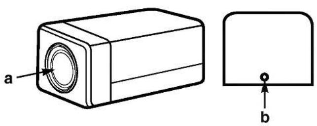
Standard Camera (LVC-CY100 NE/NC)

natural_image
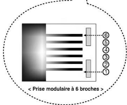
Technical line drawing of a rectangular electronic component with a circular cutout and an inset view labeled 'b' (no text or symbols beyond labels)
< 6-pin modular jack >
| pin number | SPEC |
| 1 | SPEAKER(COLD) |
| 2 | VIDEO OUT |
| 3 | GND |
| 4 | SPEAKER(HOT) |
| 5 | AUDIO OUT/ALARM OUT |
| 6 | 12V DC |

a Lens
It has a focal length of 3.7mm and makes it possible for you to observe a relatively wide area.
b Camera Fixing Nut
Enables the camera to be fixed onto the bracket.
c Microphone
Capable of picking up all sounds in the vicinity of the camera location and transmitting them to the monitor.
d Sensor jack
Used to connect the sensor to the camera.
e 6-pin modular jack
Used to connect the camera to the monitor.
f Speaker
It outputs the sound signal which was transferred from the monitor.
Motion Sensing Camera (LVC-CS100 NE/NC)

< 5-Pin terminal block >
| pin number | SPEC | |
| 1 | DC INPUT | +12V |
| 2 | GND | |
| 3 | (Not used) | |
| 4 | Alarm output | ALARM |
| 5 | COM | |
a Speaker
It outputs the sound signal which was transferred from the monitor.
b Lens
It has a focal length of 3.7mm and makes it possible for you to observe a relatively wide area.
c Fresnel lens
An infrared focusing lens for increasing the sensitivity of the built-in PIR motion sensor.
< 6-Pin modular jack >
| pin number | SPEC |
| 1 | SPEAKER(COLD) |
| 2 | VIDEO OUT |
| 3 | GND |
| 4 | SPEAKER(HOT) |
| 5 | AUDIO OUT/ALARM OUT |
| 6 | 12V DC |
d 5-Pin terminal block
A terminal block for supplying backup power for the PIR motion sensor operation during power outages and for transmitting the relay signals to external devices during the PIR motion sensor operation.
Pin number 4 and 5 of the terminal block : Contact Switch
e 6-pin modular jack
Used to connect the camera to the monitor.
Monitor Front
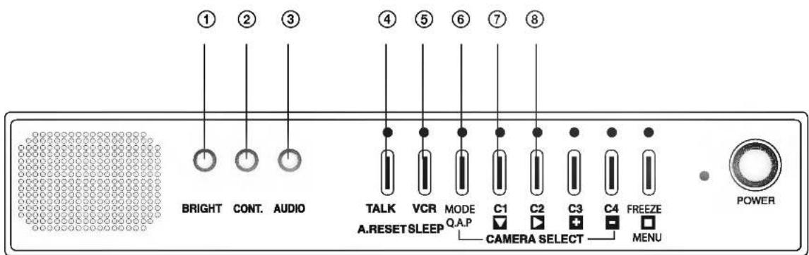
① BRIGHT
Adjust brightness with this knob.
② CONT.
Adjust contrast with this knob.
③ AUDIO
Adjust volume control for proper sound level.
④ TALK/A.RESET
• Auto mode: Talk to selected channel.
• Manual mode: Talk to selected channel.
- Quad mode: Talk to selected channel. (Selection: Go on pressing the talk button and press the camera number.)
A. RESET: Reset Alarm.
⑤ VCR/SLEEP
VCR: This button is used to display data recorded in the VCR on the monitor.
SLEEP: The monitor is turned off when you press and hold this button for more than 3 seconds. And the monitor is turned on when you press this button one more time. (During this mode, other buttons are not operational.)
⑥ Mode (Quad, Auto, PIP)
- Quad mode/Auto mode/ Small PIP mode Large mode Selection.
• Quad mode: Green LED on.
• Auto mode: Green LED blinks. - PIP mode: Green LED off.
- Manual mode: Green LED off.
⑦ C1 (CAMERA 1)
• Quad mode: Freezes channel 1.
- With Talk button: Audio selected to channel 1.
- AUTO mode: Channel 1 of the manual mode is selected.
- MENU mode: ▼ key.
- If camera is connected, green LED on and if camera is disconnected, green LED off.
⑧ C2 (CAMERA 2)
• Quad mode: Freezes channel 2.
- With Talk button: Audio selected to channel 2.
- AUTO mode: Channel 2 of the manual mode is selected.
- MENU mode: ▶ key.
- If camera is connected, green LED on and if camera is disconnected, green LED off.

⑨ C3 (CAMERA 3)
• Quad mode: Freezes channel 3.
- With Talk button: Audio selected to channel 3.
- AUTO mode: Channel 3 of the manual mode is selected.
- MENU mode: + key.
- If camera is connected, green LED on and if camera is disconnected, green LED off.
⑩ C4 (CAMERA 4)
• Quad mode: Freezes channel 4.
- With Talk button: Audio selected to channel 4.
- AUTO mode: Channel 4 of the manual mode is selected.
- MENU mode: - key.
- If camera is connected, green LED on and if camera is disconnected, green LED off.
⑪ FREEZE/MENU
- Quad mode: Activates menu mode only in quad mode.
- Auto/Manual mode: Freezes displayed channel.
- PIP mode: Freezes main display in the PIP.
- Menu mode: Enter key.
⑫ POWER LED
- MAIN Power LED.
⑬ POWER ON/OFF
- Main power switch
- It turns the main power ON or OFF.
Monitor Rear

① MAIN POWER
- Connect the power cord.
② CAMERA IN (CAM1\~CAM4)
- Four input ports for four cameras. (6 Pin Modular Jack)
③ ALARM OUTPUT
- When an alarm from the camera or the monitor is occurred, the alarm signal will output for one second. (Active Low)
• This terminal is TTL level of the open collector type.
④ V.HOLD
- Use to correct when the picture rolls up and down.
⑤ H.HOLD
• Use to correct when the picture is twisted.
⑥ AUDIO IN/OUT//VIDEO IN/OUT
• AUDIO IN, OUT / VIDEO IN, OUT
: Use when you want to connect the monitor to the recording system.
1) INSTALLING STANDARD CAMERA
Caution to install Black&White Camera outdoors
- LVC-CY100NE/NC is designed to be protected from water drops which are falling on the upper side of the camera in a range of 15^ .
(water protection level: IPX2)
Therefore, be sure to install it in a location which is fit for the above condition when you install it outdoors.
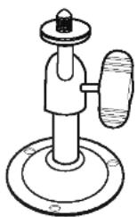
STANDARD CAMERA can be attached to the wall, ceiling or shelf using the camera mount bracket.
- Choose an installation site that can sufficiently support the weight of the equipment to be installed.
- Attach the camera mount bracket to the wall or ceiling using the three screws supplied.
- Adjust the camera to target the video location and tighten the bracket handle on the camera mount bracket.
natural_image
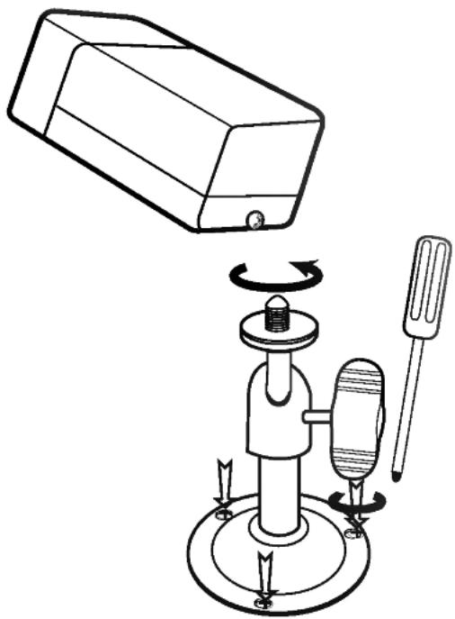
Diagram of a mechanical device with rotating components and a rectangular housing (no text or symbols)2) How to Install
① Overview
The CAMERA MOUNT BRACKET is used to attach the camera to a wall, ceiling or shelf.
② Installation
Explains the installation of the CAMERA MOUNT BRACKET as well as the installation of the camera onto the CAMERA MOUNT BRACKET.
- Choose an installation site that can sufficiently support the weight of the equipment to be installed.
- Attach the camera mount bracket to the wall using the screws supplied.

natural_image
Technical line drawing of a mechanical clamp device with screw and base mount (no text or symbols)
- Tighten the handle, turning it clockwise, and lock the camera into position using the knob. Adjust the camera to target the video location and tighten the bracket handle on the camera mount bracket.
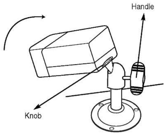
- If you want to watch another location, loosen the handle by turning it in a counter-clockwise direction and then adjust the camera to target the new video location. Then tighten the handle, turning it clockwise, and lock the camera into position.
- Connect the camera cable to the camera.
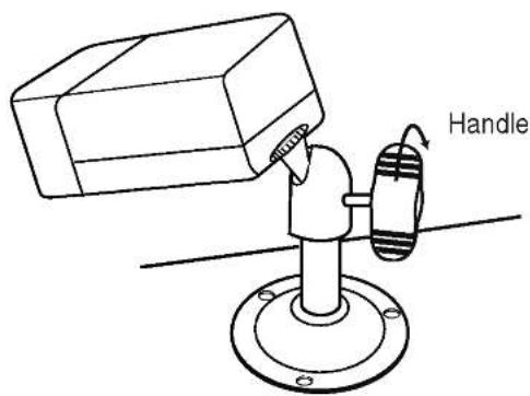
- Use the hood when the camera operates with strong sunlight or moisture.

Motion Sensing Camera (LVC-CS100 NE/NC)
a Microphone
Capable of picking up all sounds in the vicinity of the camera location and transmitting them to the monitor.
b PIR Motion Sensor
A thermal heat sensor that detects infrared radiation projected by warm objects.
c Function Switch
A function switch for the PIR Motion Sensor operation.

| pin number | Function |
| 1 | Sensor SensitivityOn, On: Low |
| 2 | On, Off: NormalOff, On: NormalOff, Off: High |
| 3 | Sensor On/Off |
| 4 | Not used |


natural_image
Solid gray rectangular shape with rounded corners, no text or symbols visible.
natural_image
Simple line drawing of a cylindrical device with a handle and control knob (no text or symbols)Motion Sensing Camera
d Electronic Relay (Photo MOS Relay)
Contact Ratings
- Maximum load current is ±130mA.
- Do not connect any system or device that has over 40V pp (DC30V) bias voltage on the contact terminal.

Sensor Detection Angle & Area
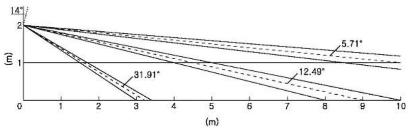
1) Vertical View Pattern
line
| (m) | 14° (°) | 5.71° (°) | 12.49° (°) | 31.91° (°) | | --- | ------- | --------- | ---------- | ---------- | | 0 | 2 | 2 | 2 | 2 | | 3 | ~0.5 | ~1.0 | ~0.8 | ~0.6 | | 10 | ~0.2 | ~0.7 | ~0.6 | ~0.4 |* Please consider the horizontal detection area and the vertical detection line when choosing an installation site.
2) Horizontal View Pattern
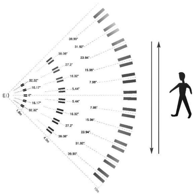
polar_bar
| Angle (°) | Value | | --------- | --------- | | 0 | 1.6 | | 16.17 | 32.32 | | 32.32 | 32.32 | | 4.3m | 38.08 | | 5.44 | 5.44 | | 7.98 | 7.98 | | 10m | 10m | | 16.17 | 16.17 | | 32.32 | 32.32 | | 4.3m | 4.3m | | 5.44 | 5.44 | | 7.98 | 7.98 | | 10m | 10m | | 16.17 | 38.08 | | 32.32 | 38.08 | | 4.3m | 5.44 | | 5.44 | 5.44 | | 7.98 | 7.98 | | 10m | 10m | | 16.17 | 32.32 | | 32.32 | 32.32 | | 4.3m | 5.44 | | 5.44 | 5.44 | | 7.98 | 7.98 | | 10m | 10m | | 16.17 | 38.08 | | 32.32 | 38.08 | | 4.3m | 5.44 | | 5.4Notes on Installation and Usage (Camera)
1 Users should not disassemble the camera from the front direction.
2 Always handle the camera with care. Please avoid shocks or vibration as much as possible and take precautions not to cause damage or make scratches on the camera due to careless storage.
3 Please do not install the camera in a rainy place or in highly humid areas. And do not operate the camera in a wet place.
4 Do not clean the camera body with strong abrasives or soaps. When the camera becomes dirty, clean it with a dry cloth. Especially, make sure to use a dedicated lens cloth to clean the front cover.
5 Please install the camera in a cool area that is not exposed to direct sunlight. If you do, it can cause bad effects on the product.
Camera Installation Hints
1 Do not install directly towards rising or setting. It can cause burn or damage to internal options.
2 Do not limit the desired detection zone by interference of curtains, screens, potted plants, etc.
3 Also, do not locate it in front of a source of water/oil vapors. Avoid placing heat sources inside the detection zone.
4 Do not install outdoors.

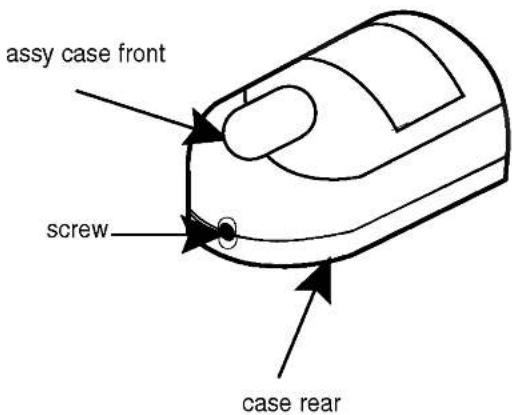
1 Choose an installation site that can sufficiently support 5 times the weight of the equipment to be installed.
2 Remove the screw (BH M2.6) at the bottom of the main unit by turning it counterclockwise, and then lift the assy-case front as you push it upward to detach it from the case-rear.
(* Do not apply excessive force, as doing so may damage the inside assembly.)
3 Place the case-rear over the installation site and mark the screw holes with a pencil (indicated by the circles in the illustration). Drill a pilot hole for each pencil mark (5mm in diameter and at least 35mm in depth), and then fully insert the plastic anchors (HUD 5) into them.

Installing the Motion Sensing Camera on the wall
natural_image
Diagram of a computer mouse with internal components and an arrow pointing to a specific area (no text or symbols present)Installing the Motion Sensing Camera in the corner
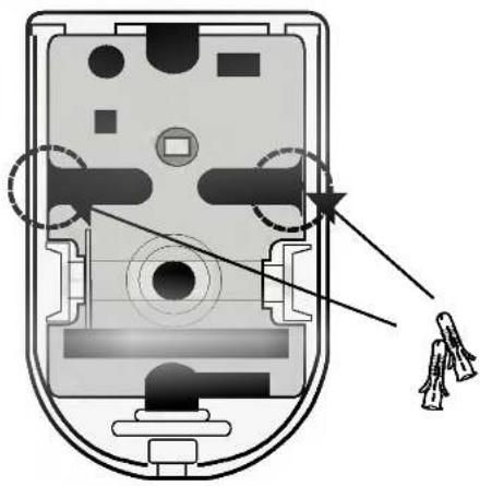
4 Connect the Camera cable connector (RJ-11) to the case-rear as well as the cable to be connected to the terminal.

5 Align the two holes of the case-rear to the holes of the plastic anchors, and then fasten the screw (BH M3 X 30).
6 Adjust the direction of the lens and the function switch for the Motion Sensing Camera.
1) Use a cross (+) screw driver to turn the screw (a) (indicated by the arrow in the illustration) counterclockwise slightly. The lens body will move.
2) Tilt the lens body down about 10^ from the horizontal, and then turn the screw clockwise to fasten it.
3) Adjust the function switch. (see page15)

7 Assemble the assy-case front onto the case-rear as shown in the illustration. Fasten the assy-case front to the case-rear with the screw you removed earlier.

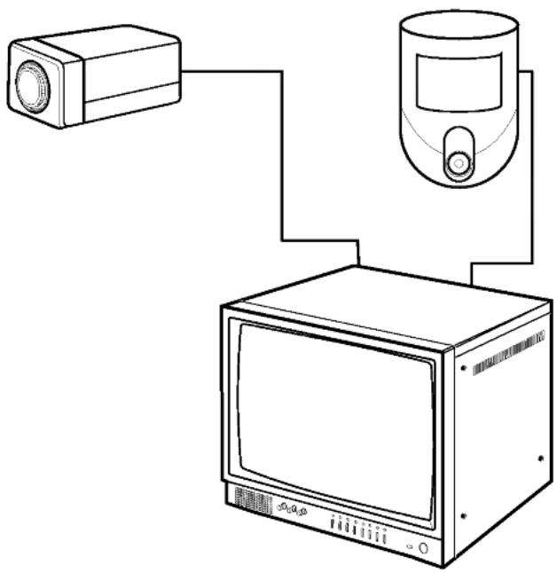
Perform the following steps to install your system.
1 Take the monitor out of the packaging box.
2 Place the monitor where you would like to install it. Do not turn on the power until the installation is completed.
3 Choose the place where you want to install the camera.
4 Once the monitor and camera locations have been chosen, install the camera.
5 Connect the cable to the jack on the back of the camera.
6 Connect the other end to CAMERA IN on the back of the monitor. (At this time, select the camera numbers and sequence.)
7 Connect the camera you wish to install (as shown below).
8 Connect the power cord from the monitor to the power outlet.
9 The power switch is on the monitor's front panel.
10 Initially the monitor is in the QUAD mode.
* After the power has been turned on, the CRT needs a stabilization period of approximately 20 seconds.
natural_image
Line drawing of a surveillance camera connected to a monitor and antenna (no text or symbols)Connecting a PIR Motion Sensor


- An additional external sensor can also be connected.
- The additional external sensor can be connected as shown in the figure above.
- The sensor's trigger signal is NO (Normal Open).
- Sensor is not supplied. (Sold separately)
Connecting a VCR
- Connect the VCR as shown below.

flowchart
graph TD
    A["CAM.2"] --> B["AC INPUT"]
    C["CAM.1"] --> B
    B --> D["CAMERA IN"]
    D --> E["3"]
    D --> F["2"]
    D --> G["3"]
    D --> H["4"]
    D --> I["AUAR OUTPUT"]
    I --> J["OUT GND"]
    J --> K["V.HOLD"]
    J --> L["H.HOLD"]
    M["VCR REAR"] --> N["ALARM"]
    N --> O["IN OUT IN OUT"]
    O --> P["AUDIO IN"]
    O --> Q["AUDIO OUT"]
    O --> R["VIDEO IN"]
    O --> S["VIDEO OUT"]
    T["<Monitor Rear>"] --> U["VCR"]
    U --> V["IN OUT VIDEO"]
    U --> W["AUDIO"]
Explanation of Screen Display
① CAMERA TITLE
- Up to 8 characters per camera.
② FREEZE
- "FREEZE" appears on the screen when you freeze each picture by button.
③ DATE/TIME
- "MM/DD/YYYY", "HH:MM:SS" is displayed on the screen
MM : Month
DD : Day
YYYY : Year
HH : Hour
MM : Minute
SS : Second
④ ALARM
- If an alarm is activated "A" appears on the screen.
⑤ LG
- If the camera is disconnected from the monitor, "LG" is displayed on the screen with a beep sounds and the last picture is memorized.
⑥ SP
- "SP" is displayed on the screen that is selected for voice transmission.
⑦ MOTION DETECT
- When the motion is detected, "M" is displayed on the screen.
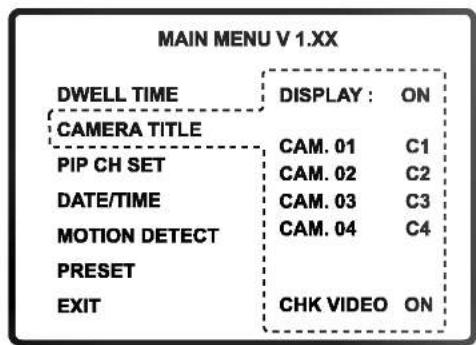
OSD and Setup Menu
- The Menu display can be accessed from the quad mode only.
- In the menu mode, quad sequential doesn't work but the alarms are on.
• If you don't control anything within 30 seconds, the menu mode is released.
① DWELL TIME SETTING
- Position the cursor in the field you would like to change by using the triangle buttons ▼ ▶ and then changes the content with the + - buttons.
- Camera alarm and dwell time can be adjusted from "skip" (0) to 60 seconds.
- CAM. 01 "SKIP" \~ 60 seconds: This is the dwell time of camera 1 when the screen is switching.
- ALARM "OFF" \~ 60 seconds: It is the display time of "A" on the screen, when an alarm occurs.
- ALARM "MUTE"\~ 60 seconds: Sounds the Alarm for the time set, when an alarm occurs.
② CAMERA TITLE
• The title name is limited to 8 characters.
- Position the cursor in the field you would like to change by using the triangle buttons ▼ ▶
and then change the content with the + - buttons.
- You can use 0\~9, A\~Z, special characters, space character.
- The OSD characters of the LG, FREEZE, SP and A (Alarm) are displayed even though the camera title mode display may be off.
- If CHK VIDEO is set to OFF, the "LG" message will not be displayed.
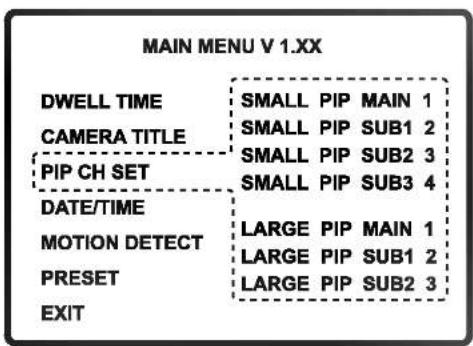
③ PIP CH SET
- Selects the channels to be displayed in the PIP mode.
- If the main or any sub window is set to "OFF", that window is not displayed.

④ DATE / TIME
- This appliance has the capability to display the time and date on the screen.
- Position the cursor in the field you would like to change by using the triangle buttons ▼ ▶ and then change the contents with the + - buttons.
- You can select ON or OFF using the DISPLAY item.
⑤ MOTION DETECT
- When Motion Detection occurs, display BEEP/ALM/OFF.
- BEEP: Motion detection only.
- ALM: Motion detection is the same as alarm setting.
- OFF: Motion detection is off.
• Area: Selects the motion detection area.
Default value is 07.
A higher value makes the sensitivity higher.
| MAIN MENU V 1.XX | ||
| DWELL TIME | DISPLAY : | ON |
| CAMERA TITLE | MONTH | 04 |
| PIP CH SET | DAY | 26 |
| DATE/TIME | YEAR | 04 |
| MOTION DETECT | HOUR | 13 |
| PRESET | MINUTE | 26 |
| EXIT | SECOND | 30 |
| MAIN MENU V 1.XX | |||
| DWELL TIME | CH STATE AREA SENS. | ||
| CAMERA TITLE | C1 OFF 15 07 | ||
| PIP CH SET | C2 OFF 15 07 | ||
| DATE/TIME | C3 OFF 15 07 | ||
| C4 OFF 15 07 | |||
| MOTION DETECT | |||
| PRESET | AREA: 1-15(FULL) | ||
| SENSITIVITY : | |||
| EXIT | 0-15 (HIGH) | ||
| 1 | 2 | 3 | 4 |
| 5 | 6 | 7 | 8 |
| 9 | 10 | 11 | 12 |
| 13 | 14 | 15 | 16 |
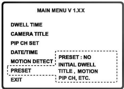
⑥ PRESET
- Please use this function only for the special purpose of initializing due to erasure of the setting values.
- Position the cursor in the field you would like to change by using the triangle buttons ▼ ▶ and then change the content with the + - buttons.
- PRESET: NO If you don't want to initialize the setting, press the □ button.
: YES When button is pressed to initialize the setting value, it displays "YES".
: OK When the initialization is completed, it displays "OK".
- Default settings
* DWELL TIME - CAM.01\~04: 03, ALARM : 60, A.SND: 60
* CAMERA TITLE - DISPLAY: ON, CAM.01\~04: C1\~C4
* PIP CH SET - SMALL PIP SUB1\~SUB4: 1\~4
LARGE PIP SUB1\~SUB3: 1\~3
* MOTION DETECT - STATE: OFF, AREA: 15, SENS.: 07
* FREEZE: melt
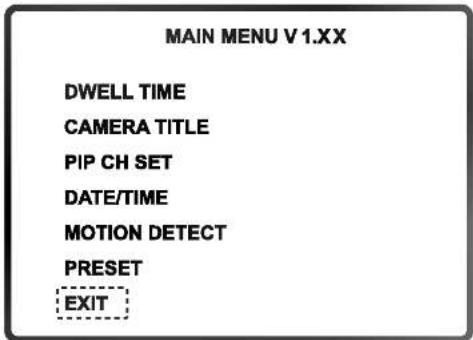
⑦ EXIT
- Exit from the menu mode.
How to Use
① QUAD SCREEN mode
- The C1 to C4 buttons can make the picture freeze or unfreeze. In this case, FREEZE appears on the screen.
- Camera connections are automatically detected and displayed in quad through the channels.
- If all cameras are disconnected, the quad mode cannot change in the sequential switching mode.
- If you want to hear the audio sound, press and hold the Talk key and choose the camera channels C1\~C4.
Channel 1: TALK key + C1 key Channel 3: TALK key + C3 key
② AUTO SEQUENTIAL SWITCHING MODE
• To set up the sequential mode, push the MODE key once at quad mode.
- The pictures are switched in full display through C1\~C4 in a sequential mode.
- Talk is active on C1\~C4 only while pushing the button and when the picture display is on the channel.
• This system detects if the cameras are connected or disconnected.
- Camera connections are also detected in the switching mode, and switching is on only for the cameras connected.
- If a camera is disconnected when switching through the channels, a beep sounds and display of that channel is skipped.
- When in the sequential switching mode, set the Freeze mode by pressing the MENU key.
• If all cameras are disconnected, the monitor automatically, switches to the quad mode.
③ MANUAL MODE
- To see only one camera picture regardless of other cameras, please press the MODE key and set the monitor in the manual mode.
- The channel is selected by one of the C1\~C4 buttons. When you push the button for a disconnected camera, "LG" will appear.
- If you push the MENU key the display freezes, push it again to release.
- The MODE key can change sequential mode from the manual mode.
④ Small PIP MODE (Picture In Picture)
- Pushing the MENU key, the main channel display can be frozen or not.
- The MODE key can change to large PIP mode from small PIP mode.
⑤ Large PIP MODE
- Pushing the MENU key, the main channel display can be frozen or not.
- The MODE key can change to quad mode from large PIP mode.
⑥ VCR MODE
- The VCR records only the picture that is shown on the monitor.
- To see the recorded picture, press the VCR key on the system.
- It doesn't work in the menu mode.
- Pushing the VCR key again, returns to the same mode as before.
⑦ ALARM FUNCTION
- The monitor can be connected to various alarms. It has an output port that sends the alarm signal to another device using the open collector method for one second. (Active low)
- When the alarm goes off in the QUAD or AUTO modes, the monitor automatically switches to the screen of the camera where the alarm is being generated and displays a blinking "A".
- If an alarm breaks out at two or more places, the monitor switches to the QUAD screen mode and displays a blinking "A" on the each screen.
- Once the alarm is released, the monitor automatically goes back to the previous mode.
- While the alarm continues, it cannot be reset. Remove the alarm factors. In the VCR or SETUP modes, the monitor switches to the alarm channel automatically.
• A.RESET resets the alarm time only after the alarm factor is removed - To disable the alarm completely (the alarm is not detected), set the alarm time to "OFF" in the Setup Menu.
- If you make the alarm off in the VCR and SETUP mode, the system doesn't go back to the VCR or SETUP mode.
- When Alarm is occurred in the SLEEP mode, the SLEEP mode is released and the display is on.
⑧ AUDIO SYSTEM
- This system has a two-way audio function. It is possible to use it from the quad mode or from the C1\~C4 full screen mode.
- You can hear the sound from the selected camera without pressing any button.
- In the quad mode, talk to the selected camera through the microphone on the monitor while you are pressing the TALK key. (You can select the channel by pressing the TALK key and the camera key simultaneously.)
⑨ OTHER FUNCTION
- If a camera is disconnected, that channel display is in freeze, and if it is connected again, the freeze will be off.
MONITOR
| Model Name | LSM-M112E | LSM-M112C |
| Picture Tube | 12"± diagonal, 90° deflection CRT | |
| Video Input | Composite video 1.0Vp-p | |
| Video Output | Composite video 1.0Vp-p | |
| Input impedance | 75 Ω | |
| Scanning system EIA standard CCIR standard | ||
| Linearity | Less than 20% (horizontal), less than 10% (vertical) | |
| Resolution | 750 TV lines at center | |
| Audio output | 0.5 W | |
| Switching dwell time | 0 to 60 seconds | |
| Alarm time | 0 to 60 seconds | |
| Microphone | Condenser microphone | |
| Power source | Universal AC input 120V, 60Hz | Universal AC input 230V, 50Hz |
| (High Temperature Protection Circuit) | ||
| Power consumption | 38W with camera | |
| Operating Temp. | 14°F ~ 122°F (-10°C ~ 50°C) (Humidity: 0%RH ~ 60%RH) | |
| Storage Temp. | -4°F ~ 140°F (-20°C ~ 60°C) (Humidity: 0%RH ~ 85%RH) | |
| Dimensions | 11.7(W) X 11.4(H) X 11.2(D) inches (297X290X285mm) | |
| Weight | Approx. 17 lb (7.5kg) | |
* Design and specifications are subject to change without prior notice.
STANDARD CAMERA
| Model | LVC-CY100NE | LVC-CY100NC |
| Signal System | EIA | CCIR |
| Total/Effective Pixels | 270K / 250K | 320K / 290K |
| Pick-Up Device | 1/3 - Inch Interline B/W CCD (Super HAD) | |
| Lens | Fixed Lens 3.7mm | |
| Iris | Electronic Shutter (ELC) | |
| Signal Process | Analog Signal Process ( S1C7309X01 ) | |
| Scanning System | 2:1 Interlace | |
| Sync. System | Internal | |
| Scanning Frequency | 59.94Hz(VD) | 50Hz(VD) |
| Resolution | 380 TV Lines (H) | 380 TV Lines (H) |
| S/N Ratio | More than 48dB | |
| Standard Illuminance | 2000Lux (3200°K) | |
| Sensitivity (1/2 Output) | 0.2 Lux (F: 2.0) | |
| Video Output Signal | 1Vp-p Composite (75Ω) | |
| Gain Control | Auto | |
| Shutter speed | Electronic Shutter(1/60 ~ 1/100000) | Electronic Shutter(1/50 ~ 1/100000) |
| Audio | -68dB Condenser Microphone Inclusion | |
| ALARM INPUT | YES | |
| Power Source | DC 12V | |
| Power Consumption | 2 W | |
| Operating Temp. | 14°F ~ 122°F (-10°C ~ 50°C) (Humidity: 0%RH ~ 60%RH) | |
| Storage Temp. | -4°F ~ 140°F (-20°C ~ 60°C) (Humidity: 0%RH ~ 85%RH) | |
| Dimensions | 0.2(W) X 0.157(H) X 0.413(D) inches (51 X 40 X 105mm) | |
| Weight | 0.33 lb (150 g) | |
* Design and specifications are subject to change without prior notice.
MOTION SENSING CAMERA
| Model | LVC-CS100NE | LVC-CS100NC |
| Signal System | EIA | CCIR |
| Total/Effective Pixels | 270K / 250K | 320K / 290K |
| Pick-Up Device | 1/3 - Inch Interline B/W CCD (Super HAD) | |
| Lens | Fixed Lens 3.7mm | |
| Iris | Electronic Shutter (ELC) | |
| Signal Process | Analog Signal Process ( S1C7309X01 ) | |
| Scanning System | 2:1 Interlace | |
| Sync. System | Internal | |
| Scanning Frequency | 59.94Hz(VD) | 50Hz(VD) |
| Resolution | 380 TV Lines (H) | 380 TV Lines (H) |
| S/N Ratio | More than 48dB | |
| Standard Illuminance | 2000Lux (3200°K) | |
| Sensitivity (1/2 Output) | 0.2 Lux (F: 2.0) | |
| Video Output Signal | 1Vp-p Composite (75Ω) | |
| Gain Control | Auto | |
| Shutter speed | Electronic Shutter(1/60 ~ 1/100000) | Electronic Shutter(1/50 ~ 1/100000) |
| Audio | -68dB Condenser Microphone Inclusion | |
| PIR Motion Sensor | Mounting height: 5ft to 10ft (1.5m to 3m) | |
| Warm-Up Period: Max. 50 seconds | ||
| Spectral Response: 7 to 14 um | ||
| Sensitivity: 4930 (V/W) | ||
| Sensor: Off/On | ||
| Alarm-COM (130mA) | ||
| Power Source | DC 12V | |
| Power Consumption | 2 W | |
| Operating Temp. | 14°F ~ 122°F (-10°C ~ 50°C) (Humidity: 0%RH ~ 60%RH) | |
| Storage Temp. | -4°F ~ 140°F (-20°C ~ 60°C) (Humidity: 0%RH ~ 85%RH) | |
| Dimensions | 0.267(W) X 0.448(H) X 0.207(D) inches (68 X 114 X 52.7mm) | |
| Weight | 0.374 lb (170 g) | |
* Design and specifications are subject to change without prior notice.
SYSTÈME DE SURVEILLANCE QUADRUPLE EN NOIR ET BLANC
MANUEL DE L'UTILISATEUR
MODÈLE: LSP-M1012E LSP-M1012C


16. Service technique
natural_image
Line drawing of a vintage CRT television set with front panel and control buttons (no text or symbols)MONITEUR

natural_image
Line drawing of a rectangular electronic device with a circular lens on top (no text or symbols)Caméra standard

natural_image
Simple line drawing of a cylindrical device with a handle and top panel (no text or symbols)natural_image
Coiled cable with connectors and a strap, no text or symbols visibleCÂBLE POUR CAMÉRA (60ft: 1EA)
natural_image
Simple line drawing of a 3D box with two screws, no text or symbols presentCAPOT DE PROTECTION et VIS
Caméra standard (LVC-CY100 NE/NC)
natural_image
Technical drawing of a rectangular electronic component with labeled parts (a and b), no text or symbols present.
| NUMÉRO DE BROCHE | SPÉC. |
| 1 | HAUT-PARLEUR (COLD) |
| 2 | SORTIE VIDÉO |
| 3 | MISE À LA TERRE |
| 4 | HAUT-PARLEUR (HOT) |
| 5 | SORTIE AUDIO/ SORTIE ALARME |
| 6 | 12V CC |
natural_image
Diagram of a mechanical device with rotating components and a rectangular housing (no text or symbols)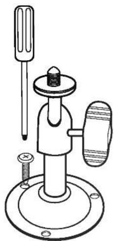
natural_image
Technical line drawing of a mechanical clamp device with screw and base mount (no text or symbols)natural_image
Solid gray rectangular shape with rounded corners, no text or symbols visible.
natural_image
Simple line drawing of a cylindrical device with a handle and top panel (no text or symbols)< Schema equivalent >
natural_image
Diagram of a computer mouse with internal components and a tassel, no text or symbols presentnatural_image
Line drawing of a vintage television set connected to a projector (no text or symbols present)- Graphic Symbol Explanation
- Warning
- IMPORTANT SAFETY INSTRUCTIONS
- FCC Warning
- CE Warning
- INTRODUCTION
- INSTALLATION
- HOW TO USE
- REFERENCE
- Caution
- Read Instructions
- Retain Instructions
- Heed Warnings
- Follow Instructions
- Cleaning
- Exception.
- Attachments
- Water and Moisture
- Accessories
- Ventilation
- Power Sources
- Grounding or Polarization
- Power
- Lightning
- Overloading
- Object and Liquid Entry
- Servicing
- Damage Requiring Service
- Replacement Parts
- Safety Check
- Standard Camera (LVC-CY100 NE/NC)
- Motion Sensing Camera (LVC-CS100 NE/NC)
- a Speaker
- b Lens
- c Fresnel lens
- d 5-Pin terminal block
- e 6-pin modular jack
- Monitor Front
- ① BRIGHT
- ② CONT.
- ③ AUDIO
- ④ TALK/A.RESET
- ⑤ VCR/SLEEP
- ⑥ Mode (Quad, Auto, PIP)
- ⑦ C1 (CAMERA 1)
- ⑧ C2 (CAMERA 2)
- ⑨ C3 (CAMERA 3)
- ⑩ C4 (CAMERA 4)
- ⑪ FREEZE/MENU
- ⑫ POWER LED
- ⑬ POWER ON/OFF
- Monitor Rear
- 1) INSTALLING STANDARD CAMERA
- 2) How to Install
- ① Overview
- ② Installation
- a Microphone
- b PIR Motion Sensor
- c Function Switch
- d Electronic Relay (Photo MOS Relay)
- Sensor Detection Angle & Area
- 1) Vertical View Pattern
- 2) Horizontal View Pattern
- Notes on Installation and Usage (Camera)
- Camera Installation Hints
- Perform the following steps to install your system.
- Connecting a PIR Motion Sensor
- Connecting a VCR
- Explanation of Screen Display
- ① CAMERA TITLE
- ② FREEZE
- ③ DATE/TIME
- ④ ALARM
- ⑤ LG
- ⑥ SP
- ⑦ MOTION DETECT
- OSD and Setup Menu
- ① DWELL TIME SETTING
- ② CAMERA TITLE
- ③ PIP CH SET
- ④ DATE / TIME
- ⑤ MOTION DETECT
- ⑥ PRESET
- ⑦ EXIT
- ① QUAD SCREEN mode
- ② AUTO SEQUENTIAL SWITCHING MODE
- ③ MANUAL MODE
- ④ Small PIP MODE (Picture In Picture)
- ⑤ Large PIP MODE
- ⑥ VCR MODE
- ⑦ ALARM FUNCTION
- ⑧ AUDIO SYSTEM
- ⑨ OTHER FUNCTION
- SYSTÈME DE SURVEILLANCE QUADRUPLE EN NOIR ET BLANC
- Service technique
- Caméra standard (LVC-CY100 NE/NC)
Brand : LG
Model : LSPM1012C
Category : Media player