
Alan 48 Pro - Radio MIDLAND - Free user manual and instructions
Find the device manual for free Alan 48 Pro MIDLAND in PDF.
| Product type | CB Radio (Citizen Band) |
| Brand | Midland |
| Model | Alan 48 Pro |
| Dimensions (W x H x D) | 180 x 50 x 150 mm |
| Weight | 1 kg |
| Power supply | 12.6 V DC ± 10% (red terminal +, black terminal -) |
| Fuse | F 2A 250V (replace with identical model) |
| Frequency bands | I, I2, D4, EU, EC, E, F, PL, UK (26.565 - 27.99125 MHz) |
| Number of channels | Up to 80 channels (depending on selected band) |
| Modulation | AM / FM |
| Transmission power | 1 W or 4 W (depending on band) |
| Antenna impedance | 50 ohms |
| Receiver sensitivity | 0.5 μV for 20 dB SINAD (AM and FM) |
| Main functions | SCAN, Dual Watch, ANL, Noise Blanker, Digital Squelch (DS), memories M1-M4, emergency channel (EMG 9), RF Gain, MIC Gain, Local/DX, PA |
| Display | Multifunction screen with icons (channel, signal level, mode, etc.) |
| Microphone | With PTT, UP/DOWN, LOCK keys |
| Rear connectors | Antenna (SO239), external S-meter, external speaker (CB and PA), power supply |
| Operating temperature | -10 °C to +55 °C |
| Installation | Mounting with supplied bracket, antenna positioned high with good ground contact, antenna cable kept away from interference sources |
| Maintenance and cleaning | Clean with a soft dry cloth. Do not use abrasive products or solvents. |
| Safety | Disconnect power before maintenance. Respect polarity. Install a bipolar switch on the power cable. |
| Spare parts and repairability | Replaceable fuse. For any other repair, contact an authorized service center. |
| General information | Compliant with European regulations. Use may be subject to national restrictions. Recycling: do not dispose of with household waste, deposit at a treatment center. |
Frequently Asked Questions - Alan 48 Pro MIDLAND
User questions about Alan 48 Pro MIDLAND
0 question about this device. Answer the ones you know or ask your own.
Ask a new question about this device
Download the instructions for your Radio in PDF format for free! Find your manual Alan 48 Pro - MIDLAND and take your electronic device back in hand. On this page are published all the documents necessary for the use of your device. Alan 48 Pro by MIDLAND.
USER MANUAL Alan 48 Pro MIDLAND
Function and location of the controls....Pag. 2
Installation....Page 4
Power supply.....Pag4
Installing an antenna....Page 4
How to operate with your transceiver....Pag.5
Frequency band selection....Pag.5
Frequency band chart....Pag.5
Technical specifications....Pag.6
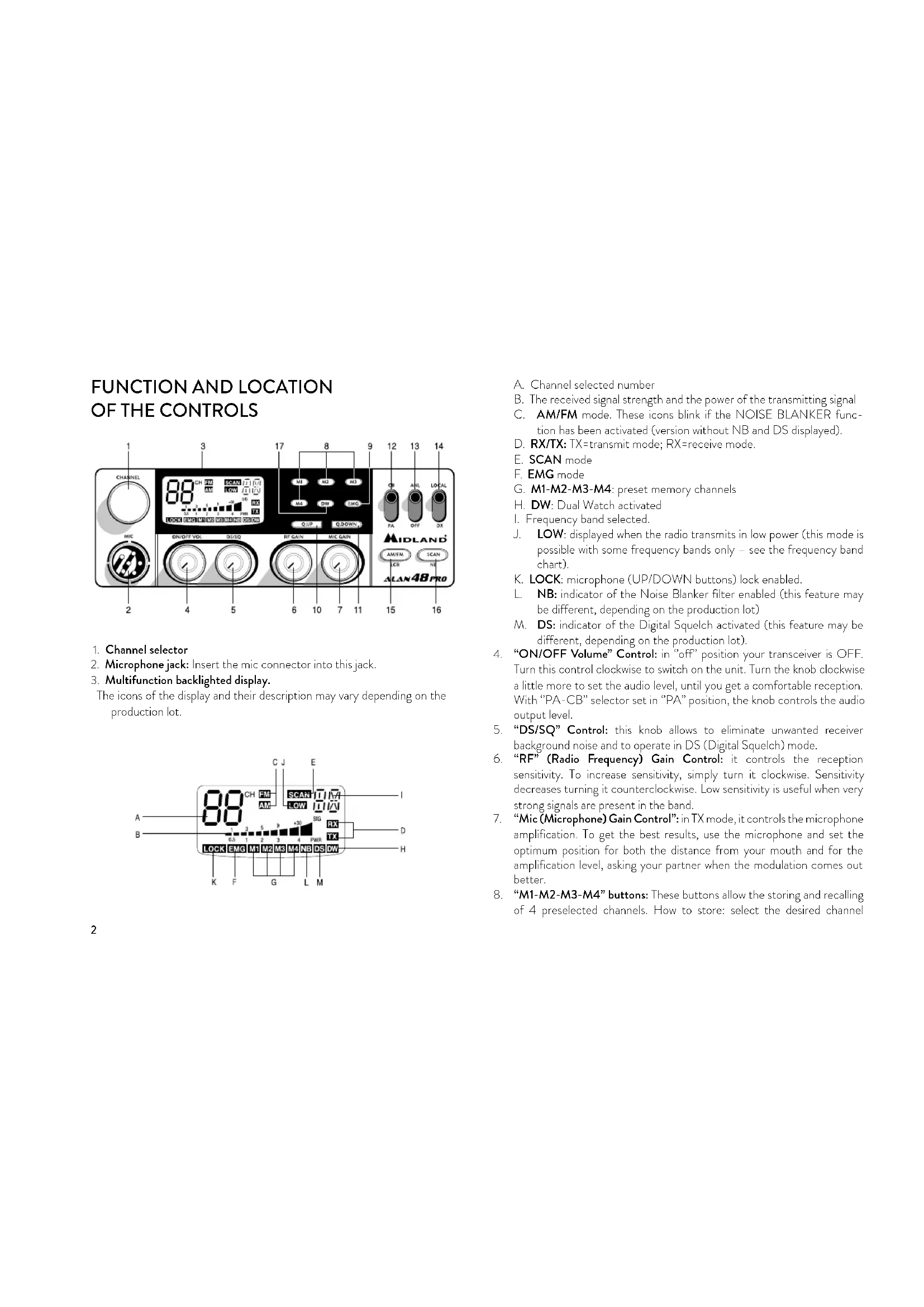
FUNCTION AND LOCATION OF THE CONTROLS
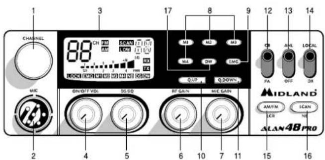
- Channel selector
- Microphone jack: Insert the mic connector into this jack.
- Multifunction backlighted display.
The icons of the display and their description may vary depending on the production lot.
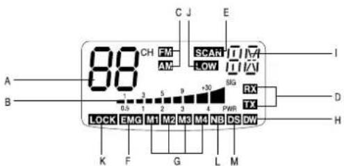
A. Channel selected number
B. The received signal strength and the power of the transmitting signal
C. AM/FM mode. These icons blink if the NOISE BLANKER function has been activated (version without NB and DS displayed).
D. RX/TX: TX=transmit mode; RX=receive mode.
E. SCAN mode
F. EMG mode
G. M1-M2-M3-M4: preset memory channels
H. DW: Dual Watch activated
1. Frequency band selected.
J. LOW: displayed when the radio transmits in low power (this mode is possible with some frequency bands only – see the frequency band chart).
K. LOCK: microphone (UP/DOWN buttons) lock enabled.
L. NB: indicator of the Noise Blanker filter enabled (this feature may be different, depending on the production lot)
M. DS: indicator of the Digital Squelch activated (this feature may be different, depending on the production lot).
"ON/OFF Volume" Control: in "off" position your transceiver is OFF. Turn this control clockwise to switch on the unit. Turn the knob clockwise a little more to set the audio level, until you get a comfortable reception. With "PA-CB" selector set in "PA" position, the knob controls the audio output level.
"DS/SQ" Control: this knob allows to eliminate unwanted receiver background noise and to operate in DS (Digital Squelch) mode.
"RF" (Radio Frequency) Gain Control: it controls the reception sensitivity. To increase sensitivity, simply turn it clockwise. Sensitivity decreases turning it counterclockwise. Low sensitivity is useful when very strong signals are present in the band.
"Mic (Microphone) Gain Control": in TX mode, it controls the microphone amplification. To get the best results, use the microphone and set the optimum position for both the distance from your mouth and for the amplification level, asking your partner when the modulation comes out better.
"M1-M2-M3-M4" buttons: These buttons allow the storing and recalling of 4 preselected channels. How to store: select the desired channel
and press M1 for at least 3 sec to store the chosen channel in the M1 memory. Repeat these steps to memorise the other presets.
- EMG button: Emergency channel. By pressing it, the unit will be automatically positioned on CH 9 (emergency channel). The display will show "EMG". It will not be possible to accidentally change the channel.
10/11. "Q. UP-Q. DOWN" buttons: To skip 10 channels up (Q. UP) or 10 channels down (Q. DOWN).
-
"CB/PA" Selector. In the "CB" position, the unit operates as a transceiver. You can use the PA (public address) function only if you connect a speaker to the PA jack. In this case the "Volume" knob controls the amplification level.
-
"ANL/OFF" Selector. In the "ANL" position it activates an automatic noise limiter for the impulsive noises (caused by the engine of the car or other sources).
-
"Local/DX" Selector "Local" position: to receive strong signal only."DX" position: to receive weak signals.
-
"AM/FM"(LCR) button: To select AM or FM mode. If you push it along with the "SCAN" button at the switching on of the radio, it selects the operating band, which will be displayed. If you select a frequency band operating in FM mode only, this button enables the LCR function (Last Channel Recall).
-
"SCAN/NB" button: with this control, you can automatically seek for a busy channel. Turn the Squelch clockwise until the background noise is no longer heard.
Press the "SCAN" button: the transceiver will scan automatically all the channels until a carrier is being received. If you push it along with the "AM/FM" button at the switching on of the radio, it selects the operating band, which will be displayed. Keep pressed this button to activate the Noise Blanker filter. To prevent interferences, this filter blocks the signal at every pulse of high peak energy, such as the car ignition noise for example.
- DW button: This feature allows you to scan 2 channels of your choice. When a signal on the second channel is picked up, the conversation on the first is automatically interrupted and the receiver switches on the second channel. The monitoring starts again 4 seconds after the carrier disappears.
To activate this function, operate as follows:
a. Select the desired channel through the channel selector.
b. Press the "DW" button (DW blinks on the display).
c. Select the second channel.
d. Push the "DW" button again: the reading DW will remain fixed.
e. To disable this function, press the "DW" control.
REAR PANEL
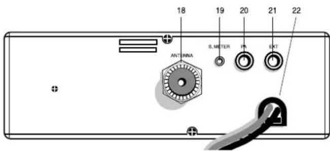
- Antenna connector (SO239 connector type).
- S. Meter jack: it allows an external "S. Meter" connection.
- "PA" jack: by connecting with an external loudspeaker, you can use the unit as an audio-amplifier.
- "EXT" jack: external loudspeaker jack (the internal loudspeaker is excluded).
- Power 12.6/24V: power supply cable.
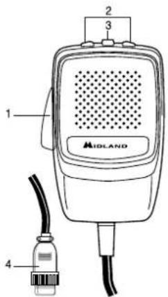
MICROPHONE
- PTT: transmission button
- UP/DOWN buttons: manual channel selector
- LOCK button: it allows you to lock the UP/DOWN buttons.
- 6 pin microphone connector
INSTALLATION
Safety and convenience are the primary consideration for mounting any piece of mobile equipment. All controls must be readily available to the operator without interfering with the movements necessary for safe operation of the vehicle. Set the proper position in the car to install the transceiver using the supplied supporting bracket or eventually the slide bracket. Tighten the retaining screws. The fixing bracket must be close to metallic parts.
POWER SUPPLY
Be sure the transceiver is off. In the direct-voltage power supply, it is very important to observe the polarity even if the unit is protected against the accidental inversion:
Red = positive pole (+)
Black = negative pole (-)
The same colors are present on the battery and in the fuse box of the car. Correctly connect the cable terminal to the battery.
ATTENTION: To obtain best performances we recommend to install the radio in a place with enough air circulation.
INSTALLING AN ANTENNA
- Place the antenna as high as possible.
- The longer is the antenna, the better will be the performance.
- If possible, mount the antenna in the center of whatever surface you choose.
- Keep antenna cable away from noise sources, such as the ignition switch, gauges, etc.
- Make sure you have a solid metal-to-metal ground connection.
- Prevent cable damage during antenna installation.
WARNING: To avoid damage, never operate your CB radio without connecting a proper antenna. A periodical control of the cable and of the S.W.R. is recommended.
REPLACING FUSE
If you replace the fuse for DC power Cord, use F 2A 250V type. The parameters and the symbol of the fuse are indicated in the following label.

HOW TO OPERATE WITH YOUR TRANSCEIVER
- Screw the microphone plug into the microphone jack.
- Make sure your antenna is securely connected to the antenna connector.
- Make sure the SQUELCH control is turned fully counterclockwise.
- Turn on the unit and adjust the volume control.
- Select your desired channel.
- To transmit, press the PTT button and speak in a normal tone of voice.
- To receive, release the PTT button.
The frequency bands must be chosen according to the country where you are going to operate.
Procedure:
- Switch off the unit.
- Turn it on while pushing the "AM/FM" e "SCAN" buttons at the same time.
- Rotate the "CHANNEL" knob and select the desired frequency band (see the chart).
- To stop your selection, press the "AM/FM" button.
NOTE: In the UK frequency band, you can select directly the I band by pushing the "AM/FM" button for 2 seconds.
NOTE ^2 : If you select a frequency band which operates in FM mode only, the "AM/FM" control enables the LCR function (Last Channel Recall).
| Digits displayed Country | |
| I Italy 40 CH AM/FM 4Watt | |
| I2 Italy 34 CH AM/FM 4Watt | |
| D4 Germany 80 CH FM 4Watt / 40 CH AM 4 Watt | |
| EU Europe 40 CH FM 4Watt / 40 CH AM 1Watt | |
| EC 40 CH FM 4Watt | |
| E Spain 40 CH AM/FM 4Watt | |
| F France 40 CH FM 4Watt / 40 CH AM 1Watt | |
| PL | Poland 40 CH AM/FM 4Watt |
| UK | England 40 CH FM 4 Watt English frequencies + I Italy 40CH AM/FM 4W |
ATTENTION!
The frequency band definitely allowed all over Europe is 40CH FM 4W (EC).
TECHNICAL SPECIFICATIONS
GENERAL
Channels .....(see the frequency band chart)
Frequency Range* 26.565 - 27.99125 MHz
Duty cycle (% on 1 hour).... TX 5% - RX 5% - Stand-by 90%
Frequency Control ....PLL
Operating Temperature Range -10°/+55°C
DC input voltage 12.6V DC ±10%
Size....180 (L)x50 (H)x150 (P) mm
Weight....1kg
RECEIVER
Receiving system .... dual conversion superheterodyne
Intermediate frequency .....I° IF: 10.695 MHz • II° IF: 455 KHz
Sensitivity....0.5μV for 20 dB SINAD in FM mode
0.5μV for 20 dB SINAD in AM mode
Audio output power @10% THD....2.0 W @ 8 Ohm
Audio distortion ....less than 8% @1 KHz
Image rejection....65 dB
Adjacent channel rejection....65 dB
Signal/Noise ratio 45 dB
Current drain at stand/by 250mA
TRANSMITTER
Output power....4W max
Modulation......AM: from 85% to 95%
FM:1,8 KHz ± 0,2 KHz
Frequency response 300 Hz/3 KHz
Output impedance....RF 50 Ohm unbalanced
Signal/Noise Ratio 40 dB MIN
Current drain....1100mA
* (covering all approved EU frequency bands)
Specifications are subject to change without notice.
A readily accessible disconnect device shall be incorporated in the installation wiring.
The disconnect device shall disconnect both poles simultaneously.
INHALT
REEMPLACEMENT DU FUSIBLE
Puissance audio....2 W @ 8 Ohms maxi
Réjection image 65 dB
Réjection canaladjacent....65 dB
Consommation....250 mA
EMETTEUR
Puissance 4 W max
Modulation.....FM 1,8 KHz ± 0,2 KHz
Consommation....1,100 A
Consum in stand/by 250mA
EMISIE
Putere 4W max
Modulatie......AM: de la 85% la 95%
FM:1,8 KHz ± 0.2 KHz
Raspuns frecventa 300 Hz/3 KHz
Impedanta....RF 50 Ohm unbalanced
Raport Semnal/Zgomot....40 dB MIN
Consum....1100mA
* (acopera toate benzile de frecventa aprobate in EU)
Specificatiile pot fi modificate fara notificare.
- All articles displaying this symbol on the body, packaging or instruction manual of same, must not be thrown away into normal disposal bins but brought to specialised waste disposal centres. Here, the various materials will be divided by characteristics and recycles, thus making an important contribution to environmental protection.
Produced or imported by: CTE INTERNATIONAL srl
Via. R.Sevardi 7 - 42124 Reggio Emilia, Italy
Imported by: Alan-Nevada UK
Unit 1 Fitzherbert Spur Farlington Portsmouth Hants P061TT,
United Kingdom - www.nevada.co.uk.
The use of this transceiver can be subject to national restrictions. Read the instructions carefully before installation and use.
Brand : MIDLAND
Model : Alan 48 Pro
Category : Radio