GAGB28KDYG - Wardrobe Gladiator - Free user manual and instructions
Find the device manual for free GAGB28KDYG Gladiator in PDF.
Download the instructions for your Wardrobe in PDF format for free! Find your manual GAGB28KDYG - Gladiator and take your electronic device back in hand. On this page are published all the documents necessary for the use of your device. GAGB28KDYG by Gladiator.
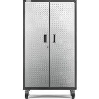
USER MANUAL GAGB28KDYG Gladiator
Modelo GAGB28KDYG - Granito Martillado/Plateado Huella GAGB28KDKSG - Granito Martillado/Granito Martillado GAGB28KDKW - Blanco Martillado/Pizarra Gris Modèle GAGB28KDYG - Ardoise Martelée/Texturé Argenté GAGB28KDKSG - Ardoise Martelée/Ardoise Martelée GAGB28KDKW - Blanc Martelé/Ardoise Grise2 You can be killed or seriously injured if you don't immediately You can be killed or seriously injured if you don't follow All safety messages will tell you what the potential hazard is, tell you how to reduce the chance of injury, and tell you what can happen if the instructions are not followed. Your safety and the safety of others are very important. We have provided many important safety messages in this manual and on your appliance. Always read and obey all safety messages. This is the safety alert symbol. This symbol alerts you to potential hazards that can kill or hurt you and others. All safety messages will follow the safety alert symbol and either the word “DANGER” or “WARNING.” These words mean: follow instructions. instructions. DANGER WARNING CABINET SAFETY3
1. Remove and verify the contents as shown in "Tools and Parts"2. Dispose of/recycle all packaging materials.
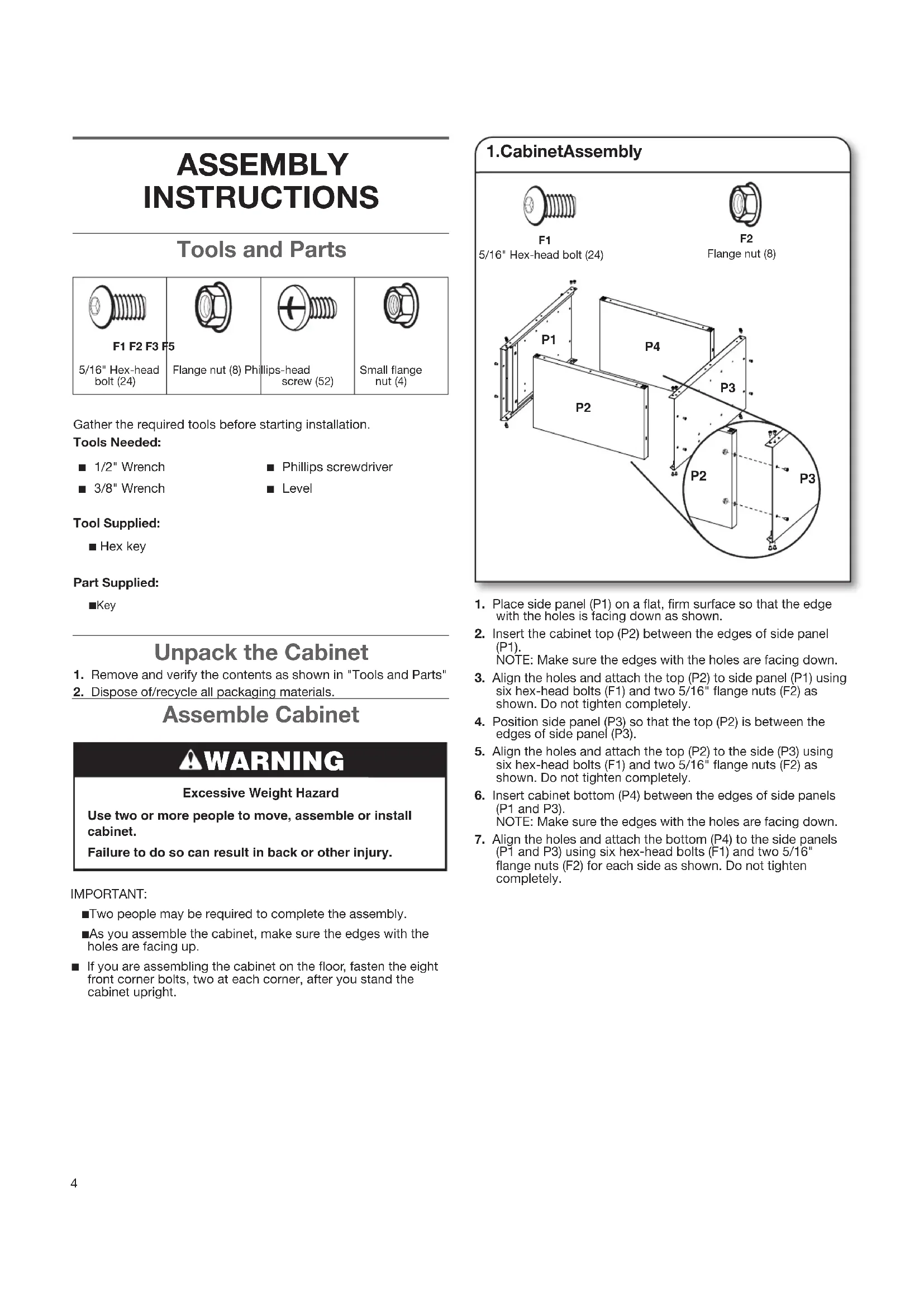
1. Place side panel (P1) on a at, rm surface so that the edge with the holes is facing down as shown.2. Insert the cabinet top (P2) between the edges of side panel (P1). NOTE: Make sure the edges with the holes are facing down. 3. Align the holes and attach the top (P2) to side panel (P1) using six hex-head bolts (F1) and two 5/16" ange nuts (F2) as shown. Do not tighten completely.4. Position side panel (P3) so that the top (P2) is between the edges of side panel (P3).5. Align the holes and attach the top (P2) to the side (P3) using six hex-head bolts (F1) and two 5/16" ange nuts (F2) as shown. Do not tighten completely.6. Insert cabinet bottom (P4) between the edges of side panels (P1 and P3). NOTE: Make sure the edges with the holes are facing down.7. Align the holes and attach the bottom (P4) to the side panels (P1 and P3) using six hex-head bolts (F1) and two 5/16" ange nuts (F2) for each side as shown. Do not tighten completely.
5/16" Hex-head bolt (24) Flange nut (8) Assemble Cabinet IMPORTANT: ■ Two people may be required to complete the assembly. ■ As you assemble the cabinet, make sure the edges with the holes are facing up. ■ If you are assembling the cabinet on the oor, fasten the eight front corner bolts, two at each corner, after you stand the cabinet upright. WARNING Excessive Weight HazardUse two or more people to move, assemble or install cabinet.Failure to do so can result in back or other injury.5
1. Using seven phillips-head screws (F3), attach the lower back panel (P6) to the bottom (P4) and sides (P1 and P3) as shown. Tighten screws completely.2. Using the hex key (provided), completely tighten all the cabinet bolts and nuts.1. Place the cabinet on its side.2. Screw a leveling foot (P7) into each of the four rivet nuts located at the corners of the cabinet as shown.3. Stand the cabinet upright.4. If you have not already, fasten the two bolts at each front corner, of the cabinet frame. Completely tighten all the cabinet bolts and nuts. NOTE: The Gladiator Modular GearBox is designed to be either stationary or to roll on casters. To order the Gladiator
Steel Modular GearBox Caster Kit, see “Accessories.” Phillips-head screw (7)
A. Leveling feet 4a. Assemble Drawer IMPORTANT: Position the drawer sides so that the glides are at the top and facing the outside.1. Working from the back, insert three Phillips-head screws (F3) through the drawer back and attach the side (D1) to the back (D2) as shown.2. Working from the back, insert three Phillips-head screws (F3) through the drawer back and attach the side (D3) to the back (D2) as shown. NOTE: Do not fully tighten the six screws attaching the drawer back (D2) to the sides (D1 and D3).3. Working from the top, set the drawer bottom (D4) down onto the back and side anges as shown.4. Working from the bottom, insert seven Phillips-head screws (F3) through the drawer back (D2), sides (D1 and D3), and then into the drawer bottom (D4). NOTE: Wait until the drawer front is in place before inserting the screws that attach the drawer bottom to the front of the sides (D1 and D3). Phillips-head screw (7)
1. Once the drawer is in place, work from the rear of the cabinet
to completely tighten the six screws attaching the drawer back.
1. Align back panel (P5) with the holes in the top (P2). Using seven
Phillips-head screws (F3), attach back panel (P5) to the top (P2) and sides (P1 and P3) as shown. Do not tighten screws completely. NOTE: Back panel (P5) will slightly overlap back panel (P6) 2.
2. Using two Phillips-head screws (F3), attach the upper back
panel (P5) to the lower back panel (P6) as shown. Completely tighten all back panel screws starting with the sides and continuing with the top, middle, and bottom.
Phillips-head screw (9)
IMPORTANT: So the doors will close and lock, the latch bar (P8) must be installed using the indicated pair of holes on each cabinet side.
1. Align the latch bar with the pair of holes shown.
NOTE: Make sure the slot in the latch bar is facing down.
2. Using two Phillips-head screws (F3) per side, fasten the latch
bar (P8) to the cabinet sides (P1 and P3).
Phillips-head screw (4)
A. Drawer screwsA. Holes for installing latch bar B. Slot in latch bar Phillips-head screw (6)
1. Using nine phillips-head screws (F3), attach the drawer front
(D5) to the bottom and sides. NOTE: Before you insert the drawer into the cabinet, make sure the bearing carriages on the cabinet slides are at the front of the cabinet.
2. Align the drawer glides with the slides on the inside of the
3. Insert the drawer glides into the slides and push the drawer
into the cabinet. NOTE: If the drawer glide is not correctly aligned with the cabinet slide, the drawer may become lodged in the cabinet. Facing the cabinet, press down on the lever located on the right-hand drawer glide while pressing up on the lever located on the lefthand drawer glide to release the drawer. A. Drawer glide lever
IMPORTANT: The door with the lock assembly (P11) should be installed on the right-hand side of the cabinet. The door hinges are designed with keyhole slots at the top and bottom so the door will hang on the cabinet while you are fastening the screws.
1. Start Phillips-head screws (F3) in both the top and bottom
holes on each side of the cabinet.
2. Hang the left-hand side door (P10) from the top and bottom
screws, and hand tighten.
3. Insert the middle two screws through the door hinge into the
cabinet and hand tighten.
4. Repeat steps 2 and 3 to attach the right-hand door (P11).
5. Align the doors and completely tighten the screws.
Phillips-head screw (6)
1. Make sure there is a bolt or screw in each hole of the cabinet frame.
2. Move the cabinet to its nal location.
3. Place a level on the inside shelf, and if necessary, level the cabinet by adjusting the height of the leveling feet (P7). Turn to the left to raise or to the right to lower the leveling foot. 4. If the doors are not aligned, loosen all the screws attaching the door hinge to the cabinet. Adjust door to the desired height, and fully tighten the screws.
IMPORTANT: The shelf (P9) may be installed using any of the lower sets of holes in the cabinet sides.
1. Place the shelf (P9) in the cabinet so that the long edge with
the door magnets is facing out.
2. Align the holes in the shelf ends with the desired set of holes
in the cabinet sides (P1 and P3).
3. Using two Phillips-head screws (F3) and two small ange nuts
P98 ACCESSORIES To order accessories, call 1-866-342-4089 and ask for the accessory part number listed below or contact your authorized Gladiator
brand dealer. In Canada, call 1-800-807-6777. Caster Kit Order Part # GACK04KDSX Modular Hardwood Top Order Part # GAAC28HWGX WARRANTY For warranty information: In the U.S.A. call 1-866-342-4089 or visit our website at www.gladiatorgarageworks.com In Canada call 1-800-807-6777 or visit our website at www.gladiatorgarageworks.ca WEIGHT CAPACITY 150 lbs. 68 kg 55 lbs.
150 lbs. 68 kg 100 lbs.
1. Working from the back, insert three Phillips-head screws (F3)
through the drawer back and attach the side (D1) to the back (D2) as shown.
4. Working from the bottom, insert seven Phillips-head screws
150 lbs. 68 kg 55 lbs.
150 lbs. 68 kg 100 lbs.
1. Working from the back, insert three Phillips-head screws (F3)
through the drawer back andattach the side (D1) to the back (D2) as shown.
3. Working from the top, set the drawer bottom (D4) down onto
the back and side anges as shown.
150 lbs. 68 kg 55 lbs.
150 lbs. 68 kg 100 lbs.