GAG33MS2L - Motherboard GIGABYTE - Free user manual and instructions
Find the device manual for free GAG33MS2L GIGABYTE in PDF.

User questions about GAG33MS2L GIGABYTE
0 question about this device. Answer the ones you know or ask your own.
Ask a new question about this device
Download the instructions for your Motherboard in PDF format for free! Find your manual GAG33MS2L - GIGABYTE and take your electronic device back in hand. On this page are published all the documents necessary for the use of your device. GAG33MS2L by GIGABYTE.
USER MANUAL GAG33MS2L GIGABYTE
| ☐ EN 55011 | Lunds and methods of measurement of radio decades建筑面积 of industrial, sanitary and municipal (GN) | ☐ EN 51000-1-2 | Distinguances in supply systems caused by households' operations and sector sectors |
| ☐ EN 55013 | Lunds and methods of measurement of radio decades建筑面积 of roaders recovers and associated equipment | ☐ EN 55024 | Information Technology requirement monthly management |
| ☐ EN 55014-1 | Lunds and methods of measurement of radio decades建筑面积 of forested electrical appliances | ☐ EN 50082-1 | General Monthly Standard Pan T subsidiary, commercial and jahr industry |
| ☐ EN 55022 | Lunds and methods of measurement of radio decades建筑面积 of equipment | ☐ EN 55022 | Influency requirements for household appliances and businesses |
| ☐ EN 55030 | Influency from radio manufacturers of broadband arrays and internetes | ☐ EN 55091-2 | ENC requirements for unmet printing power systems (JWS) |
| ☐ EN 55021 | Lunds and methods of measurement of radio decades建筑面积 of information arrays and internetes | ☐ EN 55014-2 | Influency requirements for household appliances and businesses |
| ☐ CN VOE 0855 | Cable distribution systems Equipment | ☐ CN VOE 0855 | Cable distribution systems Equipment for necessary and distribution from sound and television spairs |
| ☐ part 19 | ☐ part 19 | ☐ CN VOE 0855 | CE |
| ☐ CN VOE 0856 | Safety requirements for means operated electronics and service apparatus for household and smaller general use | ☐ EN 50501 | Safety for information technology equipment including regional business equipment |
| ☐ EN 60335 | Safety of household and similar electrical appliances | ☐ EN 50501-1 | General and Safety requirements for unmet ppable power systems (JPS) |
| ☐ EN 60065 | Safety requirements for means operated electronics and service apparatus for household and smaller general use | ☐ EN 50501 | Safety for information technology equipment |
Date: Oct. 22, 2007
Signature: Eric Lu
Representative Person's Name: ERIC LU
including that may cause undesired operation.
cause harmful and (2) this device must accept any interest received,
subject to the following two conditions: (1) This device may not
This device complies with part 15 of the FCC Rules. Operation is
Supplementary Information:
(a),Class B Digital Device
FCC Part 15, Subpart B, Section 15.107(a) and Section 15.109
Confirms to the following specifications:
Model Number: GA-G33M-S2L
Product Name: Motherboard
horby declares that the product
Phone/Fax No:(818) 854-9338/ (818) 854-9339
City of Industry, CA 91748
Address: 17358 Railroad Street
Responsible Party Name: G.B.T.INC. (U.S.A.)

Per FCC Part 2 Section 2.1077(a)
DECILARATION OF CONFORMITY
版權
2-5 Integrated Peripherals (整合週邊設定) 37
2-6 Power Management Setup (省電功能設定) 40
2-7 PnP/PCI Configurations ( 隨插即用與 PCI 組態設定) 42
2-8 PC Health Status (電腦健康狀態) 43
2-9 MB Intelligent Tweaker(M.I.T.) ( 頻率/電壓控制) 44
2-10 Load Fail-Safe Defaults (载入最安全預設值) 48
2-11 Load Optimized Defaults (载入最佳化預設值) 48
2-12 Set Supervisor/User Password (設定管理者/使用者密碼) 49
2-13 Save & Exit Setup (儲存設定值並結束設定程式) 50
2-14 Exit Without Saving (結束設定程式但不儲存設定值) 50
第三章 驅動程式安裝 51
natural_image
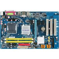
Close-up of a computer motherboard with CPU socket and RAM slots (no visible text or symbols)text_image
Diagram of a computer motherboard with labeled components and an arrow indicating direction or flow.
natural_image
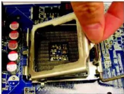
Close-up of a hand inserting a CPU into a motherboard with visible traces and components (no text or symbols)步驟二:
移除 CPU 插槽上的保護蓋。
natural_image
Close-up of a hand pressing a CPU socket on a motherboard (no visible text or symbols)步驟三:
再將 CPU 插槽上的金屬上蓋翻起。
natural_image
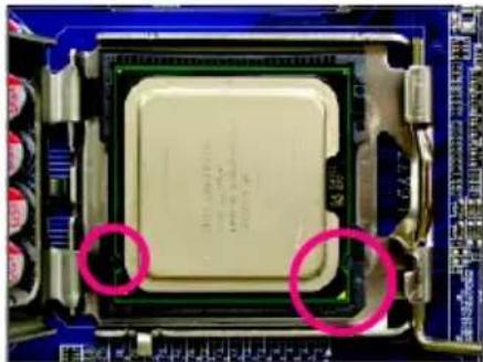
Close-up of a computer processor with two red-circled annotations highlighting the chip's surface (no readable text or symbols)步驟四:
以拇指及食指拿取 CPU GPU 的第
一腳位置(三)形標示 對齊 插槽
上的第一腳缺角處(OF)是將 上的
凹角對齊插槽上的凸角)輕輕放入。
natural_image
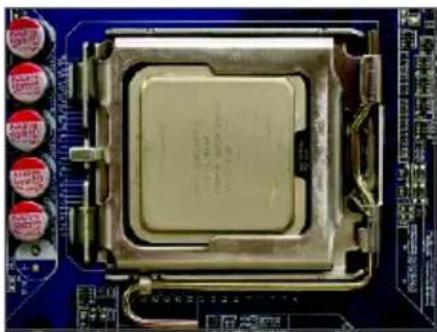
Close-up of a computer processor on a blue circuit board (no visible text or symbols)步驟五:
natural_image
Close-up of a computer processor's head andCPU socket (no visible text or symbols)步驟一:
natural_image
Close-up of a computer motherboard with visible CPU socket and cooling fan (no text or symbols)步驟三:
natural_image
Close-up of a small electronic component with a metallic pin inserted into a blue circuit board (no visible text or symbols)步驟五:
natural_image
Close-up of a mechanical component with a highlighted circular area, placed on a blue circuit board (no visible text or symbols)步驟四:
natural_image
Close-up of a CPU socket on a motherboard with visible traces and components (no readable text or symbols)步驟六:
text_image
Diagram showing computer motherboard with labeled RAM slots and a magnified view of DDR11-14可啟動雙通道記憶體的組合如下表:
natural_image
Close-up of hands installing a computer motherboard with cooling fans and heats (no visible text or symbols)步驟一:
natural_image
Close-up of a computer motherboard with red and blue CPU slots, no visible text or symbols步驟二:
text_image
Diagram of a computer motherboard with labeled components and an inset magnified view highlighting internal structure.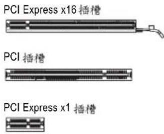
text_image
PCI Express x16 插槽 PCI 插槽 PCI Express x1 插槽natural_image
Close-up of hands holding a computer motherboard with visible CPU socket, RAM slots, and heatsink (no text or symbols)- 安装顯示卡:
natural_image
Close-up of a finger pressing down on a black electronic component with visible traces and pads (no text or symbols)- 移除顯示卡:
text_image
Diagram of electronic device rear panel with labeled ports and connectorsPS/2 键盤及 滑鼠插座
連接 PS/2 鍵盤及滑鼠至此插座。
natural_image
Computer motherboard diagram showing CPU socket, RAM slots, and memory card (no text or labels)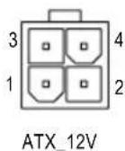
ATX_12V :
natural_image
Top-down view of a computer motherboard showing CPU socket, RAM slots, and memory card (no text or labels visible)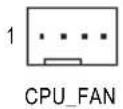
CPU_FAN :
natural_image
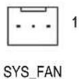
Top-down schematic of a computer motherboard showing CPU socket, RAM slots, and connectors (no text or labels)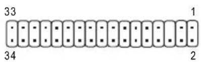
text_image
33 34 1 26) IDE (IDE) 插座
natural_image
Diagram of a computer motherboard showing CPU socket, RAM slots, and connectors (no text or labels)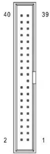
text_image
40 39 2 1natural_image
Exploded view diagram of a computer motherboard showing CPU socket, RAM slots, and memory card (no text or labels)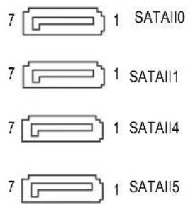
text_image
7 1 SATAII0 7 1 SATAII1 7 1 SATAII4 7 1 SATAII5natural_image
Yellow cable with black connectors, one highlighted in pink (no text or symbols)natural_image
Exploded view diagram of a computer motherboard showing CPU socket, RAM slots, and memory card (no text or labels)1
text_image
Diagram of a computer motherboard layout with labeled components and connectors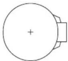
natural_image
Simple line drawing of a circular object with a plus sign at center and a rectangular base (no text or symbols)text_image
Diagram of a computer motherboard layout with labeled components and connectors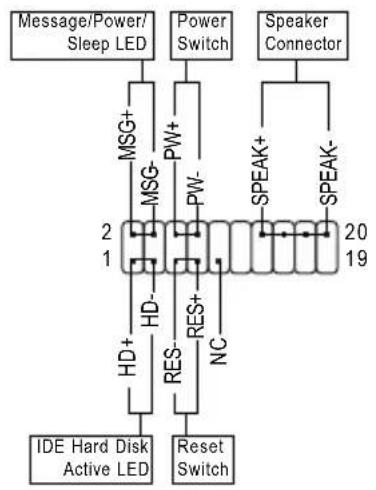
flowchart
graph TD
    A["Message/Power/Sleep LED"] --> B["MSG+"]
    B --> C["MSG-"]
    C --> D["HD-"]
    D --> E["RES-"]
    E --> F["Reset Switch"]
    G["Power Switch"] --> H["PW+"]
    H --> I["PW-"]
    I --> J["2"]
    J --> K["19"]
    L["Speaker Connector"] --> M["SPEAK+"]
    M --> N["SPEAK-"]
    O["IDE Hard Disk Active LED"] --> P["HD+"]
    P --> Q["RES-"]
    Q --> R["NC"]
-MSG (Message/Power/Sleep LED) —訊息指示燈:
natural_image
Diagram of a computer motherboard layout showing CPU socket, RAM slots, and memory card (no text or labels)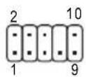
HD 接頭定義:
| 接腳 | 定義 |
| 1 MIC2_L | |
| 2 | 接地腳 |
| 3 MIC2_R | |
| 4 -ACZ_DET | |
| 5 LINE2_R | |
| 6 FAUDIO_JD | |
| 7 | 接地腳 |
| 8 | 無接腳 |
| 9 LINE2_L | |
| 10 FAUDIO_JD | |
AC'97 接頭定義:
natural_image
Top-down schematic of a computer motherboard showing CPU socket, RAM slots, and memory card (no text or labels)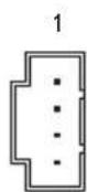
natural_image
Diagram of a computer motherboard showing CPU socket, RAM slots, and memory card (no text or labels)1 ■ ■ ■
natural_image
Diagram of a computer motherboard showing CPU socket, RAM slots, and memory card (no text or labels)9 1 10 - - - - - - 2
text_image
Diagram of a computer motherboard layout with labeled components including CPU socket, RAM slots, and indicator lights8 開路:一般運作
8 短路:清除 CMOS 資料

natural_image
Diagram of a computer motherboard layout showing CPU socket, RAM slots, and memory card (no text or labels)8 1
| 接腳 | 定義 |
| 1 | 訊號腳 |
| 2 | 接地腳 |
第二章 BIOS 組態設定
▶ F11 Save CMOS to BIOS
▶ F12 Load CMOS from BIOS
■ Integrated Peripherals (整合週邊設定)
| Date (mm:dd:yy) | Thu, Sep 27 2007 | Item Help |
| Time (hh:mm:ss) | 11:31:24 | Menu Level▶ |
| IDE Channel 0 Master | [None] | |
| IDE Channel 1 Master | [None] | |
| IDE Channel 2 Master | [None] | |
| IDE Channel 3 Master | [None] | |
| IDE Channel 4 Master | [None] | |
| IDE Channel 4 Slave | [None] | |
| Drive A | [1.44M, 3.5"] | |
| Floppy 3 Mode Support | [Disabled] | |
| Halt On | [All, But Keyboard] | |
| Base Memory | 640K | |
| Extended Memory | 501M | |
| Total Memory | 503M | |
| ↑↓→←: Move Enter: Select +/-/PU/PD: Value F10: Save ESC: Exit F1: General Help F5: Previous Values F6: Fail-Safe Default F7: Optimized Defaults | ||
▶ IDE Channel 0/1 Master
▶ Extended IDE Drive
2-4 Advanced BIOS Features ( BIOS
功能設定
CMOS Setup Utility-Copyright (C) 1984-2007 Award Software Advanced BIOS Features
| Hard Disk Boot PriorityFirst Boot DeviceSecond Boot DeviceThird Boot DevicePassword CheckHDD S.M.A.R.T. CapabilityLimit CPUID Max. to 3 (※)No-Execute Memory Protect (※)CPU Enhanced Halt (CIE) (※)CPU Thermal Monitor 2(TM2) (※)CPU EIST Function (※)Virtualization Technology (※)Init Display FirstOnboard VGAOn-Chip Frame Buffer Size | [Press Enter][Floppy][Hard Disk][CDROM][Setup][Disabled][Disabled][Enabled][Enabled][Enabled][PCI][Enable If No Ext PEG][8MB+1~2MB for GTT] | Item Help |
| Menu Level▶ | ||
| ↑↓→←: Move Enter: Select +/-/PU/PD: Value F10: Save ESC: Exit F1: General HelpF5: Previous Values F6: Fail-Safe Defaults F7: Optimized Defaults | ||
Hard Disk Boot Priority (選擇開機硬碟
CPU Enhanced Halt (C1E) (Intel® C1E 功能 (註)
2-5 Integrated Peripherals (整合週邊設定)
| SATA AHCI Mode [Disabled] SATA Port0-1 Native Mode [Disabled] USB Controller [Enabled] USB 2.0 Controller [Enabled] USB Keyboard Support [Disabled] USB Mouse Support [Disabled] Legacy USB storage detect [Enabled] Azalia Codec [Auto] Onboard H/W LAN [Enabled] SMART LAN [Press Enter] OnBoard LAN Boot ROM [Disabled] Onboard IDE Controller [Enabled] Onboard Serial Port 1 [3F8/IRQ4] Onboard Parallel Port [378/IRQ7] Parallel Port Mode [SPP] | Item Help |
| Menu Level▶ | |
| ↑↓→←: Move Enter: Select +/-/PU/PD: Value F10: Save ESC: Exit F1: General Help F5: Previous Values F6: Fail-Safe Defaults F7: Optimized Defaults | |
SATA AHCI Mode
| Start detecting at Port..... | Item Help | |||||
| Pair1-2 Status = Open / Length = 0.0m | Menu Level▶ | |||||
| Pair3-6 Status = Open / Length = 0.0m | ||||||
| Pair4-5 Status = Open / Length = 0.0m | ||||||
| Pair7-8 Status = Open / Length = 0.0m | ||||||
| ↑↓→←: Move Enter: Select +/-/PU/PD: Value F10: Save ESC: Exit F1: General Help F5: Previous Values F6: Fail-Safe Defaults F7: Optimized Defaults | ||||||
Start detecting at Port....
Link Detected --> 100Mbps
Cable Length= 30m
例:Pair1-2 Status = Short / Length = 1.6m
Onboard IDE Controller
Onboard Parallel Port (內建並列埠
| ACPI Suspend Type Soft-Off by PWR-BTTN PME Event Wake Up Power On by Ring Resume by Alarm x Date (of Month) Alarm x Time (hh:mm:ss) Alarm HPET Support(##) HPET Mode(##) Power On By Mouse Power On By Keyboard x KB Power ON Password AC Back Function | [S3(STR)] [Instant-Off] [Enabled] [Enabled] [Disabled] Everyday 0:0:0 [Enabled] [32-bit mode] [Disabled] [Disabled] Enter [Soft-Off] | Item Help |
| Menu Level▶ | ||
| ↑↓→←: Move Enter: Select +/-/PU/PD: Value F10: Save ESC: Exit F1: General Help F5: Previous Values F6: Fail-Safe Defaults F7: Optimized Defaults | ||
▶ S1(POS) ACPI S1 (POS Power On Suspend)
Soft-Off by PWR-BTTN (關機方式
Power On by Ring (數據機開機)
Resume by Alarm (定時開機
Power On by Mouse (滑鼠開機功能
Power On by Keyboard (鍵盤開機功能
text_image
CMOS Setup Utility-Copyright (C) 1984-2007 Award Software PnP/PCI Configurations PCI1 IRQ Assignment [Auto] PCI2 IRQ Assignment [Auto] ↑↓→←: Move Enter: Select +/-/PU/PD: Value F10: Save ESC: Exit F1: General Help F5: Previous Values F6: Fail-Safe Defaults F7: Optimized Defaults Item Help Menu Level▶3,4,5,7,9,10,11,12,14,15
由 自動指定。預設值
3,4,5,7,9,10,11,12,14,15
由 自動指定。預設值
Current CPU/SYSTEM FAN Speed (RPM) (偵測風扇轉速
自動偵測 CPU/ 系統風扇的轉速。
CPU Warning Temperature (CPU) 温度警告
text_image
x Read To Precharge Delay 2 Auto x tRD 5 Auto x tRD Phase Adjustment 0 Auto ******** System Voltage Optimized ******** System Voltage Control [Manual] DDR2 OverVoltage Control [Normal] FSB OverVoltage Control [Normal] CPU Voltage Control [Normal] Normal CPU Vcore 1.32500V ↑↓→←: Move Enter: Select +/-/PU/PD: Value F10: Save ESC: Exit F1: General Help F5: Previous Values F6: Fail-Safe Defaults F7: Optimized Defaults Item Help Menu Level▶
CPU Clock Ratio (CPU) 倍頻調整 (推
DRAM RAS# to CAS# Delay
選項包括:Auto(預設15、
DRAM RAS# Precharge
選項包括:Auto(預設值、
Precharge delay (tRAS)
選項包括:Auto(預設3d、
- ACT to ACT Delay (tRRD)
選項包括:Auto(預設值、
Rank Write To READ Delay
選項包括:Auto(預設3d、
Write To Precharge Delay
選項包括:Auto(預設3d、
Refresh to ACT Delay
選項包括:0\~255 (0)預設值:
Read To Precharge Delay
選項包括:Auto(預設15、
tRD
選項包括:Auto(預設值、
tRD Phase Adjustment
選項包括:Auto(預設31、
System Voltage Control (系統超電壓設定
Standard CMOS Features
▶ Advanced BIOS Features
▶ Integrated Peripherals
Power Management Setup
PnP/PCI C Enter Password:
PC Health Status
MB Intelligent Tweaker(M.I.T.)
ESC: Quit
↑↓→←: Select Item
F11: Save CMOS to BIOS
F8: Q-Flash F10: Save & Exit Setup F12: Load CMOS from BIOS
Change/Set/Disable Password
text_image
GIGABYTE Intel® P35/P31/G31/G33/G35/Q33/Q35/X38 (Hyper Utilities CD) 安装片组 驱动程式 软體應用程式 驅動程式光確 資訊 健體資訊 與我們聯繫 交換芯片驅動器格式 我們建議系統的主驅框並以T所列出的驅動程式。直接-T "Xpress Install" 未啟動它將所有驅動程式。 你必須讓您取消要更安全的驅動程式。取消您取消你的驅動程式將不予安装。 Click the "Xpress Install" button to install all selected drivers. Click the "Install" button to install the drivers individually. Xpress Install Yahoo! Toolbar Size 696.1KB Version 1.0 Yahoo! Toolbar Utility INF Update Utility Size 2.5MB Version 8.3.1.009 This utility installs INF files that inform the operating system how to properly configure the impulse for specific functionally such as PCHExpress or USB Interface. Intel! Graphics Media Accelerator Driver Size 41.3MB Version 6.14.10.4851 Installs drivers for the integrated graphics controller of Intel@Chipsets. This is not to be used if the system has a third party graphics card. To Enelte HDMI, Make sure the "Microsoft UAA Bus driver for High Definition Audio" has been installed from the motherboard driver disk and your operation system has been updated with the latest Service Pack for Windows before installing the graphics card driver. Microsoft UAA Bus driver for High Definition Audio Size 2.5MB Version 5.10.0.5010 The Microsoft UAA Universal Audio Architecture Bus driver provides support for High Definition Audio (Racks). This driver is designed to work with the following versions of i?Windows: 1 Microsoft Windows Server 2003 2 Microsoft Windows XP Service Pack 1/2 (SP1/SP2) 3 Microsoft Windows 2000 Service Pack 4 (SP4) Microsoft HD Audio Driver Xpress Install "Xpress Install" 使用 [Click and Do] 效用并自动安装驅動程式。請選擇想要的驅動程式,然後使用一下「Xpress Install」使用,"Xpress Install"將會自動取付安裝工作。
text_image
. . Boot from CD/DVD: Press any key to startup XpressRecovery2.....圖 8
text_image
Q-Flash Utility v2.05 Flash Type/Size......SST 25VF080B 1M Keep DMI Data Enable Update BIOS from Drive 0 file(s) found vc En Floppy A- BIOS Enter>要更新的
檔案並按下
鍵。

text_image
Q-Flash Utility v2.05 Flash Type/Size............SST 25VF080B 1M Keep DMI Data Enable !! Copy BIOS completed - Pass!! Please press any key to continue步驟四:
text_image
Please select our file to update WARNING: Before you select the model name from the list below, please select the end model name to snow macrobeed. If you select the wrong model name to update the BPC, you may appear would not want. Model Name: OA-KINKP-QLI WNTCA xPlane10L, A RASS-BOG, Var F11 OK Cancel步驟三:
text_image
Update New BIOS 100% End步驟一:
text_image
Message Do you want to Update BIOS ? 確定 取消步驟三:
natural_image
Close-up of hands installing a black electronic component on a circuit board (no visible text or symbols)步驟一:
natural_image
Close-up of a computer motherboard with a white cable inserted into a socket (no visible text or symbols)步驟二:
natural_image
Close-up of a finger inserting a small electronic component into a computer drive (no visible text or symbols)S/PDIF 同軸輸出線
步驟三:
natural_image
Close-up of a finger pressing a button on a computer interface (no visible text or symbols)S/PDIF 光纖輸出線
B. S/PDIF 音效輸出設定:
natural_image
Windows XP desktop wallpaper showing a green hill under a blue sky with clouds, no visible text or symbols on the main image area.步驟二:
natural_image
Windows XP desktop wallpaper showing a green hill under a blue sky with clouds, no visible text or symbols on the screen.步驟四:
Management Methods on Control of Pollution from Electronic Information Products
(China RoHS Declaration)
G.B.T. INC. (U.S.A.)
G.B.T Inc (USA)
G.B.T. TECHNOLOGY TRADING GMBH
Representative Office Of GIGA-BYTE Technology Co., Ltd. in CZECH REPUBLIC
網址:http://www.gigabyte.cz
土耳其
Representative Office Of GIGA-BYTE Technology Co., Ltd. in TURKEY
Moscow Representative Office Of GIGA-BYTE Technology Co., Ltd.
Office of GIGA-BYTE TECHNOLOGY Co., Ltd. in POLAND
Representative Office Of GIGA-BYTE Technology Co., Ltd. in Romania
Representative Office Of GIGA-BYTE Technology Co., Ltd. in SERBIA & MONTENEGRO