GAP31S3G - Motherboard GIGABYTE - Free user manual and instructions
Find the device manual for free GAP31S3G GIGABYTE in PDF.
User questions about GAP31S3G GIGABYTE
0 question about this device. Answer the ones you know or ask your own.
Ask a new question about this device
Download the instructions for your Motherboard in PDF format for free! Find your manual GAP31S3G - GIGABYTE and take your electronic device back in hand. On this page are published all the documents necessary for the use of your device. GAP31S3G by GIGABYTE.
USER MANUAL GAP31S3G GIGABYTE
| ☐ EN 55011 | Lunds and methods of measurement of radio distribution certificate or industrial services and municipal (GN) high frequency equipment | ☐ EN 51000-1-2 | Distributions in supply systems caused by households' operations and sector sectors |
| ☐ EN 55013 | Lunds and methods of measurement of radio distribution certificate or broadband recoveries and associated equipment | ☐ EN 55024 | Information Technology requirement monthly management |
| ☐ EN 55014-1 | Lunds and methods of measurement of radio distribution certificate or broadband electrical appliances | ☐ EN 50082-1 | General monthly standard Pan T subsidiary, commercial and jahr industry |
| ☐ EN 55016 | Lunds and methods of measurement of radio distribution certificate or broadband electrical appliances | ☐ EN 50082-2 | General monthly standard Pan T industrial system |
| ☐ EN 55020 | Invenuity from radio manufacturers of broadband receivers and associated equipment | ☐ EN 50091-2 | ENC requirements for unmet printing power systems (JWS) |
| ☐ EN 55022 | Lunds and methods of measurement of radio distribution certificate or broadband lamps and businesses | ☐ EN 50091-2 | Cable distribution systems Equipment for necessary and distribution from sound and television spairs |
| ☐ CN VOE 0855 | Cable distribution systems Equipment | ☐ EN 5050 | CE Company margin! |
| ☐ CN 60065 | Safety requirements for means operated electronics and service opportunities for household and smaller general use | ☐ EN 5050 | Sany for information technology equipment including regional business equipment |
| ☐ EN 60335 | Safety of household and similar electrical appliances | ☐ EN 50091-1 | General and safety requirements for unmet ppable power systems (JPS) |
| ☐ CE Marketing | Manufacturing/processor | Signature: | Tianay Huang |
| (Stamp) | Date: Sep. 21, 2007 | Name: | |
Date: Sept. 21, 2007
Signature: Eric Lu
Reperesentative Person's Name: ERIC LU
including that may cause undesired operation.
cause harmful and (2) this device must accept any interest received,
subject to the following two conditions: (1) This device may not
This device complies with part 15 of the FCC Rules. Operation is
Supplementary information:
(a),Class B Digital Device
FCC Part 15, Subpart B, Section 15.107(a) and Section 15.109
Confirms to the following specifications:
Model Number: GA-P31-S3G
Product Name: Motherboard
horby declares that the product
Phone/Fax No:(818) 854-9338/ (818) 854-9339
City of Industry, CA 91748
Address: 17358 Railroad Street
Responsible Party Name: G.B.T.INC. (U.S.A.)

Per FCC Part 2 Section 2.1077(a)
DECILARATION OF COMPANY
版權
natural_image
Close-up of a blue printed circuit board with electronic components and a circular logo (no readable text or symbols)
natural_image
Close-up of a computer motherboard with visible CPU socket, RAM slots, and circuit board (no text or symbols)目錄
清點配件 6
選購配件 6
GA-P31-S3G 主機板配置圖 7
晶片組功能方塊圖 8
第一章 硬體安裝 9
1-1 安裝前的注意須知 9
1-2 產品規格....10
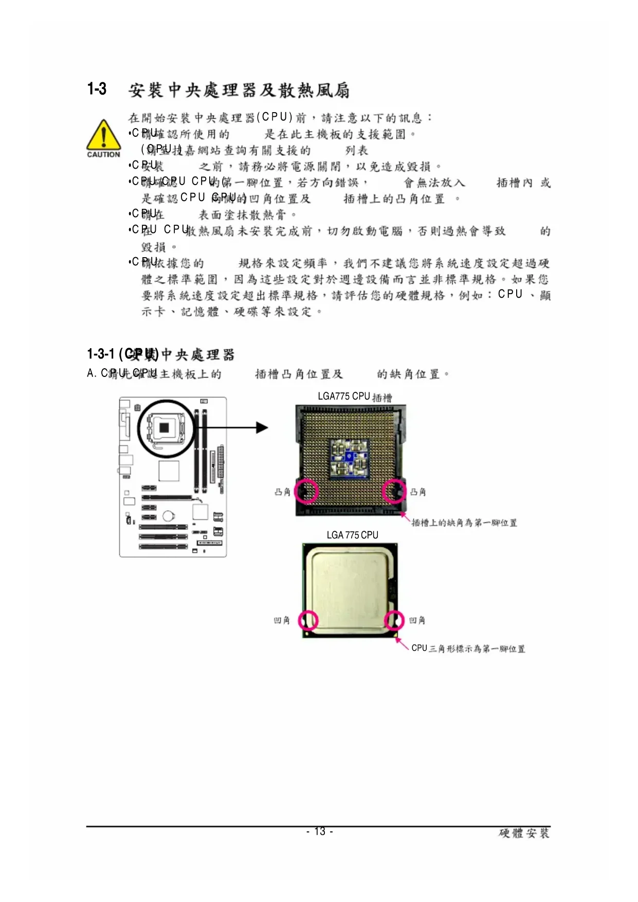
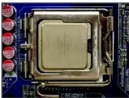
1-3 安装中央處理器及散熱風扇 13
2-5 Integrated Peripherals (整合週邊設定) 39
2-6 Power Management Setup ( 省電功能設定) 42
2-7 PnP/PCI Configurations ( 隨插即用與 PCI 組態設定) 44
2-8 PC Health Status (電腦健康狀態) 45
2-9 MB Intelligent Tweaker(M.I.T.) ( 頻率/電壓控制) 46
2-10 Load Fail-Safe Defaults (载入最安全預設值) 49
2-11 Load Optimized Defaults (载入最佳化預設值) 49
2-12 Set Supervisor/User Password (設定管理者/使用者密碼)....50
2-13 Save & Exit Setup (儲存設定值並結束設定程式) 51
2-14 Exit Without Saving (結束設定程式但不儲存設定值) 51
第三章 驅動程式安裝 53
natural_image
Top-down view of a computer motherboard showing CPU socket, RAM slots, and drive bays (no text or symbols visible)natural_image
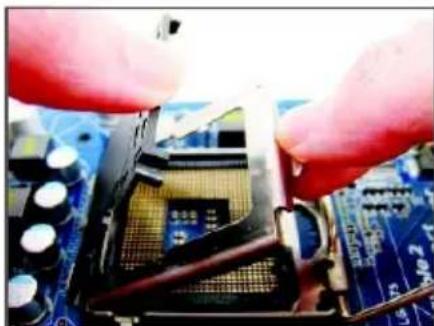
Close-up of a hand holding a black CPU socket on a blue circuit board (no visible text or symbols)步驟二:
將 CPU 插槽上的金屬上蓋翻起。
(CPJ)觸摸 插槽的接觸點。
natural_image
Close-up of hands holding a CPU socket on a blue circuit board (no visible text or symbols)步驟三:
將 CPU 插槽保護蓋從金屬上蓋移除。
(○)保護 插槽,主機板沒有安裝
CPU 時,請將保護蓋放回金屬上蓋。
natural_image
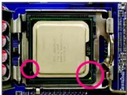
Close-up of a CPU socket with two circled regions highlighting the components (no visible text or symbols)步驟四:
以拇指及食指拿取 CPU GPU 的第
一腳位置( )CPU形標示 對齊 插槽
上的第一腳缺角處(OP)是將 上的
凹角對齊插槽上的凸角)輕輕放入。
natural_image
Close-up of a CPU socket on a blue circuit board (no visible text or symbols)步驟五:
natural_image
Close-up of a computer motherboard with a CPU socket and surrounding circuit components (no visible text or symbols)步驟一:
natural_image
Close-up of a computer motherboard with a black CPU fan and visible traces, no text or symbols present.步驟三:
natural_image
Close-up of a small electronic component with a metallic body and white base, placed on a blue circuit board (no visible text or symbols)步驟五:
natural_image
Close-up of a mechanical component with a highlighted circular area, placed on a blue circuit board (no visible text or symbols)步驟四:
natural_image
Close-up of a CPU socket on a motherboard with visible traces and components (no readable text or symbols)步驟六:
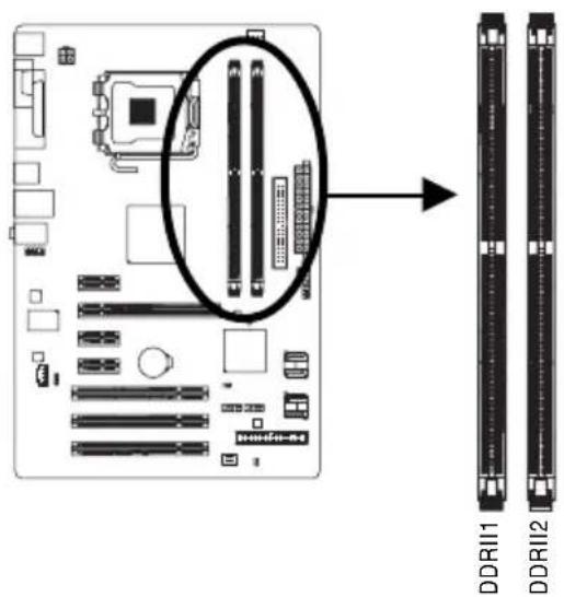
▶ 通道0 (Channel 0) DDRII1 (1)插槽
▶ 通道1 (Channel 1) DDRII2 (2) 插槽
text_image
Diagram of a computer motherboard showing CPU socket, drive bays, and memory card connectors with an arrow indicating assembly or mapping.natural_image
Close-up of hands installing a computer motherboard with cooling fans and heat sinks (no visible text or symbols)步驟一:
natural_image
Close-up of a computer motherboard with red and blue CPU slots, no visible text or symbols步驟二:
natural_image
Close-up of hands holding a computer motherboard with visible CPU socket and RAM slots (no text or symbols)- 安裝顯示卡:
natural_image
Close-up of a finger pressing down on a keyboard (no visible text or symbols)- 移除顯示卡:
text_image
Diagram of a computer interface panel with labeled ports and connectorsPS/2 鍵盤及 滑鼠插座
連接 PS/2 鍵盤及滑鼠至此插座。
text_image
Labeled diagram of a computer motherboard showing CPU socket, RAM slots, and drive components with numbered partsnatural_image
Top-down view of a computer motherboard showing CPU socket, RAM slots, and various hardware components (no text or labels visible)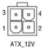
ATX_12V :
natural_image
Top-down view of a computer motherboard showing CPU socket, RAM slots, and memory drive (no text or labels)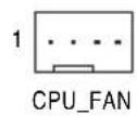
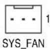
CPU_FAN :
natural_image
Top-down schematic of a computer motherboard showing CPU socket, RAM slots, and memory drive components (no text or labels)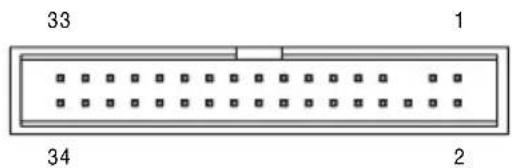
text_image
33 1 34 26) IDE (IDE) 插座
natural_image
Computer motherboard layout diagram showing CPU socket, RAM slots, and memory card (no text or labels)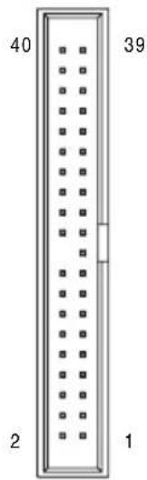
text_image
40 39 2 1natural_image
Top-down schematic of a computer motherboard showing CPU socket, RAM slots, and memory drive components (no text or labels)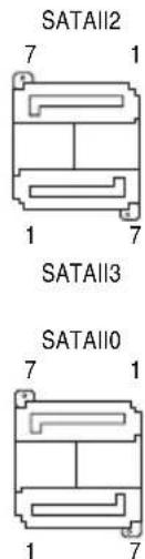
text_image
SATAII2 7 1 1 7 SATAII3 SATAII0 7 1 1 7SATAII1
規格。一個 插
natural_image
Yellow cable with black connectors, one circled in pink (no text or symbols visible)natural_image
Top-down schematic of a computer motherboard showing CPU socket, RAM slots, and memory drive layout (no text or labels)1
natural_image
Top-down schematic of a computer motherboard showing CPU socket, RAM slots, and various memory units (no text or labels)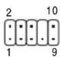
HD 接頭定義:
| 接腳 | 定義 |
| 1 MIC2_L | |
| 2 | 接地腳 |
| 3 MIC2_R | |
| 4 -ACZ_DET | |
| 5 LINE2_R | |
| 6 FAUDIO_JD | |
| 7 | 接地腳 |
| 8 | 無接腳 |
| 9 LINE2_L | |
| 10 FAUDIO_JD | |
AC'97 接頭定義:
natural_image
Top-down schematic of a computer motherboard showing CPU socket, RAM slots, and memory card layout (no text or labels)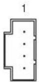
natural_image
Top-down schematic of a computer motherboard showing CPU socket, RAM slots, and memory drive layout (no text or labels)1
natural_image
Top-down schematic of a computer motherboard showing CPU socket, RAM slots, and memory drive components (no text or labels)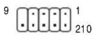
natural_image
Top-down schematic of a computer motherboard showing CPU socket, RAM slots, and memory drive layout (no text or labels)開路:一般運作
短路:清除 CMOS 資料

text_image
Diagram of a computer motherboard layout with labeled components including CPU socket, RAM slots, and drive bays8 1
| 接腳 | 定義 |
| 1 | 訊號腳 |
| 2 | 接地腳 |
16) BAT (電池
natural_image
Top-down schematic of a computer motherboard showing CPU socket, RAM slots, and memory drive components (no text or labels)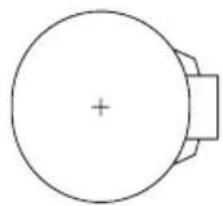
natural_image
Simple line drawing of a circular object with a plus sign at center and a rectangular base (no text or symbols)▶ F11 Save CMOS to BIOS
▶ F12 Load CMOS from BIOS
■ Integrated Peripherals (整合週邊設定)
▶ IDE Channel 0 Master [None] ▶ IDE Channel 0 Slave [None] ▶ IDE Channel 2 Master [None] ▶ IDE Channel 2 Slave [None] ▶ IDE Channel 3 Master [None] ▶ IDE Channel 3 Slave [None]
Drive A [1.44M, 3.5"] Floppy 3 Mode Support [Disabled]
Halt On [All, But Keyboard]
Base Memory 640K Extended Memory 510M Total Memory 512M
↑↓→←: Move Enter: Select +/-/PU/PD: Value F10: Save ESC: Exit F1: General Help F5: Previous Values F6: Fail-Safe Defaults F7: Optimized Defaults
Date (mm:dd:yy) (日期設定)
▶ IDE Channel 0 Master/Slave
▶ Extended IDE Drive
▶ Precomp (Precompensation) 償磁區
| Hard Disk Boot Priority [Press Enter]First Boot Device [Floppy]Second Boot Device [Hard Disk]Third Boot Device [CDROM]Password Check [Setup]HDD S.M.A.R.T. Capability [Disabled]CPU Multi-Threading [IMAGE] [Enabled]Limit CPUID Max. to 3 [IMAGE] [Disabled]No-Execute Memory Protect [IMAGE] [Enabled]CPU Enhanced Halt (C1E) [IMAGE] [Enabled]CPU Thermal Monitor 2(TM2) [IMAGE] [Enabled]CPU EIST Function [IMAGE] [Enabled]Virtualization Technology [IMAGE] [Enabled]Full Screen LOGO Show [Enabled]Init Display First [PCI] | Item Help | ||||
| Menu Level▶ | |||||
| ↑↓→←: Move Enter: Select +/-/PU/PD: Value F10: Save ESC: Exit F1: General HelpF5: Previous Values F6: Fail-Safe Defaults F7: Optimized Defaults | |||||
Hard Disk Boot Priority (選擇開機硬碟)
CPU Enhanced Halt (C1E) (Intel® C1E 功能) (註)
| On-Chip Primary PCI IDE [Enabled] On-Chip SATA Mode [Auto] x PATA IDE Set to Ch.0 Master/Slave SATA Port 0/2 Set to Ch.2 Master/Slave SATA Port 1/3 Set to Ch.3 Master/Slave USB Controller [Enabled] USB 2.0 Controller [Enabled] USB Keyboard Support [Disabled] USB Mouse Support [Disabled] Legacy USB storage detect [Enabled] Azalia Codcc [Auto] Onboard H/W LAN [Enabled] SMART LAN [Press Enter] Onboard LAN Boot ROM [Disabled] Onboard Serial Port 1 [3F8/IRQ4] Onboard Parallel Port [378/IRQ7] Parallel Port Mode [SPP] | Item Help | |
| Menu Level▶ | ||
| ↑↓→←: Move Enter: Select +/-/PU/PD: Value F10: Save ESC: Exit F1: General Help F5: Previous Values F6: Fail-Safe Defaults F7: Optimized Defaults | ||
On-Chip Primary PCI IDE (晶片組內建 IDE 控制介面)
text_image
CMOS Setup Utility-Copyright (C) 1984-2007 Award Software SMART LAN Start detecting at Port.... Pair1-2 Status = Open / Length = 0.0m Pair3-6 Status = Open / Length = 0.0m Pair4-5 Status = Open / Length = 0.0m Pair7-8 Status = Open / Length = 0.0m ↑↓→←: Move Enter: Select +/-/PU/PD: Value F10: Save ESC: Exit F1: General Help F5: Previous Values F6: Fail-Safe Defaults F7: Optimized Defaults Item Help Menu Level▶Start detecting at Port.... Link Detected --> 100Mbps Cable Length=30m
▶ Link Detected h 顯示 傳輸速度
▶ Cable Length 10m顯示網路線的大約線長。若線長少於「Cable length less than 10M」。
例:Pair1-2 Status = Short / Length = 1.6m
Onboard Parallel Port (內建並列埠
| ACPI Suspend Type [S3(STR)] Soft-Off by PWR-BTTN [Instant-Off] PME Event Wake Up [Enabled] Power On by Ring [Enabled] Resume by Alarm [Disabled] x Date (of Month) Alarm Everyday x Time (hh:mm:ss) Alarm 0 : 0 : 0 HPET Support [us] HPET Mode [us] Power On By Mouse [Disabled] Power On By Keyboard [Disabled] x KB Power ON Password Enter AC Back Function [Soft-Off] | [Enabled] [32-bit mode] | Item Help |
| Menu Level▶ | ||
| ↑↓→←: Move Enter: Select +/-/PU/PD: Value F10: Save ESC: Exit F1: General Help F5: Previous Values F6: Fail-Safe Defaults F7: Optimized Defaults | ||
Soft-Off by PWR-BTTN (關機方式)
Power On by Ring (數據機開機)
Resume by Alarm (定時開機
Power On By Keyboard (鍵盤開機功能
text_image
CMOS Setup Utility-Copyright (C) 1984-2007 Award Software PnP/PCI Configurations PCI1 IRQ Assignment [Auto] PCI2 IRQ Assignment [Auto] PCI3 IRQ Assignment [Auto] ↑↓→←: Move Enter: Select +/-/PU/PD: Value F10: Save ESC: Exit F1: General Help F5: Previous Values F6: Fail-Safe Defaults F7: Optimized Defaults Item Help Menu Level▶3,4,5,7,9,10,11,12,14,15
由 自動指定。預設值
3,4,5,7,9,10,11,12,14,15
由 自動指定。預設值
3,4,5,7,9,10,11,12,14,15
由自動指定。預設值
CMOS Setup Utility-Copyright (C) 1984-2007 Award Software PC Health Status
| Reset Case Open Status [Disabled]Case Opened NoVcore 1.438VDDR18V 1.840V+3.3V 3.344V+12V 12.112VCurrent CPU Temperature 47Current CPU FAN Speed 3375 RPMCurrent SYSTEM FAN Speed 0 RPMCPU Warning Temperature [Disabled]CPU FAN Fail Warning [Disabled]SYSTEM FAN Fail Warning [Disabled]CPU Smart FAN Control [Enabled] | °C | Item Help |
| Menu Level▶ | ||
| ↑↓→←: Move Enter: Select +/-/PU/PD: Value F10: Save ESC: Exit F1: General HelpF5: Previous Values F6: Fail-Safe Defaults F7: Optimized Defaults | ||
Reset Case Open Status (重置機殼狀況)
Current CPU Temperature (偵測 CPU 溫度)
自動偵測 CPU 的溫度。
Current CPU/SYSTEM FAN Speed (RPM) (偵測風扇轉速)
自動偵測 CPU/ 系統風扇的轉速。
CPU Warning Temperature (CPU 溫度警告)
| Robust Graphics Booster [Auto] CPU Clock Ratio (a) [18X] CPU Host Clock Control [Disabled] x CPU Host Frequency (Mhz) 200 PCI Express Frequency (Mhz) [Auto] Performance Enhance [Turbo] System Memory Multiplier (SPD) [Auto] Memory Frequency (Mhz) 800 800 ***** System Voltage Optimized ***** System Voltage Control [Manual] DDR2 OverVoltage Control [Normal] PCI-E OverVoltage Control [Normal] FSB OverVoltage Control [Normal] (G)MCH OverVoltage Control [Normal] CPU Voltage Control [Normal] Normal CPU Vcore 1.38750V | Item Help |
| Menu Level▶ | |
| ↑↓→←: Move Enter: Select +/-/PU/PD: Value F10: Save ESC: Exit F1: General Help F5: Previous Values F6: Fail-Safe Defaults F7: Optimized Defaults | |

Standard CMOS Features
▶ Advanced BIOS Features
▶ Integrated Peripherals
Power Management Setup
PnP/PCI C Enter Password:
PC Health Status
MB Intelligent Tweaker(M.I.T.)
ESC: Quit
↑↓→←: Select Item
F11: Save CMOS to BIOS
F8: Q-Flash F10: Save & Exit Setup F12: Load CMOS from BIOS
Change/Set/Disable Password
"Xpress Install " is now analyzing your computer...99%
text_image
Scanned screenshot of a Windows file explorer window showing drive information and system details in Chinese.图 5
text_image
Boot from CD/DVD: Press any key to startup XpressRecovery2.....图8
text_image
GIGABYTE™ TECHNOLOGY RESTORE NOW... This is a version of Power Specificator, Data Capier: HAN51-67000.圖
E. Xpress Recovery2 (Remove) 功能
text_image
Q-Flash Utility v2.02 Flash Type/Size......ATMEL 26F004 512K !! Copy BIOS completed - Pass!! Please press any key to continue步驟四:
text_image
Please select one file to update WARNING: Before you select the model name from the list below, please select the one model name on your mainboard. If you select the wrong model name to update the IDOC, your computer would not boot. Model Name : OA-0009-011 NOTICE: uPrint4_011, A WARD-0009, Ver F1 OK Cancel步驟三:
text_image
Message Do you want to Update BIOS ? 确定 取消步驟三:
text_image
Scanned screenshot of a Windows file explorer window showing folder navigation and printer icons with Chinese labels.步驟一:
natural_image
Close-up of hands installing a black electronic component on a circuit board (no visible text or symbols)步驟一:
natural_image
Close-up of a white plug inserted into a computer motherboard with visible CPU socket and circuit board (no text or symbols)步驟二:
natural_image
Close-up of a hand inserting a small electronic component into a computer drive (no visible text or symbols)S/PDIF 同軸輸出線
步驟三:
natural_image
Close-up of a finger pressing a button on a computer interface (no visible text or symbols)S/PDIF 光纖輸出線
B. S/PDIF 音效輸出設定:
natural_image
Windows XP desktop wallpaper showing a green hill under a blue sky with clouds, no visible text or symbols on the screen.步驟二:
natural_image
Computer desktop wallpaper showing a green hill under a blue sky with clouds, no visible text or symbols.步驟四:
Management Methods on Control of Pollution from Electronic Information Products
(China RoHS Declaration)