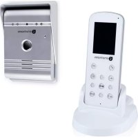
10.008.92 - Intercom SMARTWARES - Free user manual and instructions
Find the device manual for free 10.008.92 SMARTWARES in PDF.



| Brand | Smartwares |
| Model | 10.008.92 |
| Product type | Wireless video doorbell |
| Monitor screen | 2.4 inches, resolution 320 x 240 |
| Outdoor camera | CMOS sensor, viewing angle 55° |
| Night vision | Yes (infrared LED) |
| Monitor power supply | 5 V DC, 1 A (power adapter included) |
| Camera power supply | 5 V DC via rechargeable Li-ion battery 3.7 V 1500 mAh |
| Monitor battery | Li-ion 3.7 V 1200 mAh |
| Camera battery | Li-ion 3.7 V 1500 mAh |
| Charging time | Approximately 5 hours |
| Wireless range | Up to 120 m in open field |
| Operating frequency | 2.4 GHz (2400-2483.5 MHz) |
| Main functions | Audio/video intercom, photo capture, door unlock (optional), indoor monitor |
| Audio | Two-way (microphone and speaker) |
| Installation | Outdoor wall mount with rain cover |
| Operating temperature | -10 °C to +50 °C |
| Storage temperature | -20 °C to +60 °C |
| Operating humidity | ≤ 85% RH |
| Safety | Do not expose to water or rain; keep out of reach of children; do not use in explosive atmosphere |
| Maintenance | Clean with a soft, dry cloth |
| Spare parts | Replacement batteries, power adapter |
| Compliance | CE |
Frequently Asked Questions - 10.008.92 SMARTWARES
User questions about 10.008.92 SMARTWARES
0 question about this device. Answer the ones you know or ask your own.
Ask a new question about this device
Download the instructions for your Intercom in PDF format for free! Find your manual 10.008.92 - SMARTWARES and take your electronic device back in hand. On this page are published all the documents necessary for the use of your device. 10.008.92 by SMARTWARES.
USER MANUAL 10.008.92 SMARTWARES
VD36W
EN Instruction manual....4.
- Please read these instructions carefully before installing and using the product.
- Do not cut the power supply cable to extend it; the transformer will not operate with a longer cable. Do not plug in the transformer until all the wiring has been finished.
- This product is not a toy. Keep it out of reach of children.
- Do not operate electrically powered products in explosive atmospheres, such as in the presence of flammable liquids, gases, or dust. Electrically powered products create sparks which may ignite the dust or fumes.
- The warnings, precautions, and instructions discussed in this instruction manual cannot cover all possible conditions and situations that may occur. It must be understood by the operator that common sense and caution are factors which cannot be built into this product, but must be supplied by the operator.
- Do not expose the Power Adapter of this product to rain or wet conditions. Water entering the Power Adapter will increase the risk of electric shock.
- Do not abuse the Power Cord. Never use the cord for unplugging the plug from the outlet. Keep cord away from heat, oil, sharp edges or moving parts. Damaged or entangled cords increase the risk of electric shock.
- The adapter must match the outlet. Never modify the plug in any way. Unmodified plugs and matching outlets will reduce risk of electric shock.
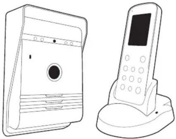
INCLUDED IN THE PACK:

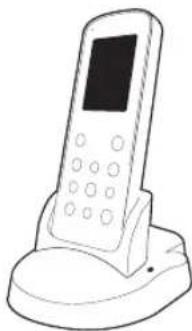
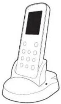
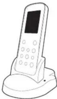
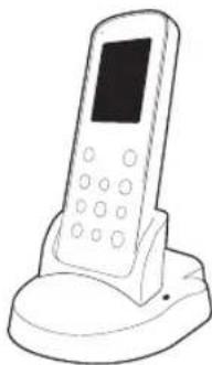
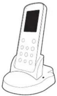
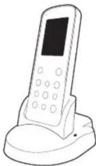
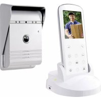
INDOOR MONITOR
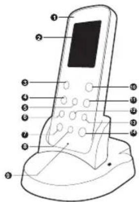
- Charging LED
- Screen
- Intercom button
- Exit Button
-
Up button
-
Left button
- Monitor / Delete button
- Down button
- Microphone
-
Unlock button
-
Power on/off
- Photo/confirm button
- Right button
- Playback/Set button
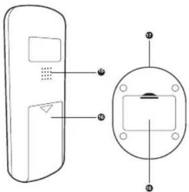
- Speaker
- Battery box
- DC in
- Outdoor battery charger
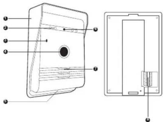
OUTDOOR INTERCOM
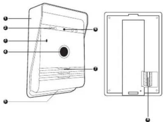
- Rain cover
- Night vision light
- Microphone
-
Call button
-
Light sensor
- Camera lens
- Speaker
- Connector box
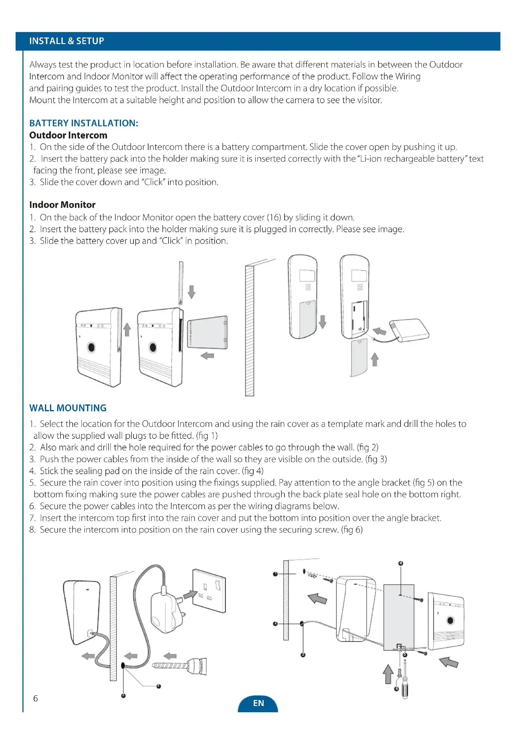
Always test the product in location before installation. Be aware that different materials in between the Outdoor Intercom and Indoor Monitor will affect the operating performance of the product. Follow the Wiring and pairing guides to test the product. Install the Outdoor Intercom in a dry location if possible. Mount the Intercom at a suitable height and position to allow the camera to see the visitor.
BATTERY INSTALLATION:
Outdoor Intercom
- On the side of the Outdoor Intercom there is a battery compartment. Slide the cover open by pushing it up.
- Insert the battery pack into the holder making sure it is inserted correctly with the "Li-ion rechargeable battery" text facing the front, please see image.
- Slide the cover down and "Click" into position.
Indoor Monitor
- On the back of the Indoor Monitor open the battery cover (16) by sliding it down.
- Insert the battery pack into the holder making sure it is plugged in correctly. Please see image.
- Slide the battery cover up and "Click" in position.
![graph TD A["Front Panel"] --> B["Signal Transmission"] B --> C["Data Transfer"] C --> D["Back Panel"] D --> E["Final Panel with Data Link"] style A fill:#f9f,stroke:#333 style B fill:#ccf,stroke:#333 style C fill:#cfc,stroke:#333 style D fill:#fcc,stroke:#333 style E fill:#cff,stroke:#333](/content/2026/03/551719/images/41ced91521aa5af1e2b972897a987cecdd730c6f04586864966c4915333c4727.jpg)
WALL MOUNTING
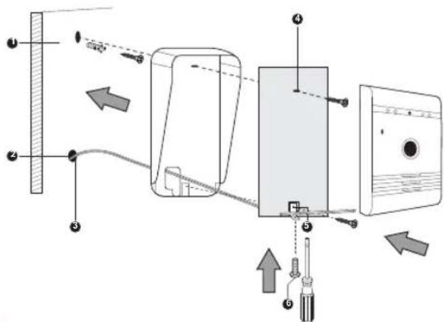
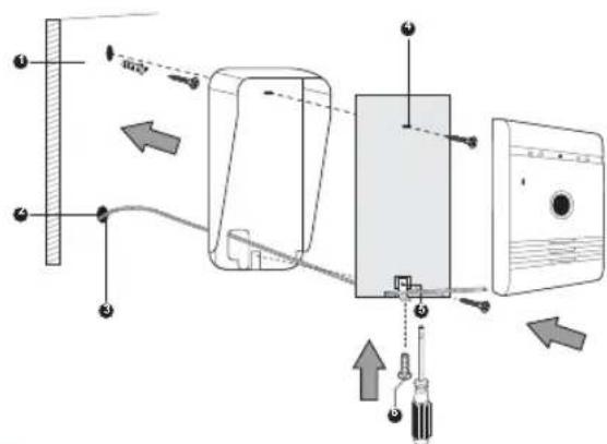
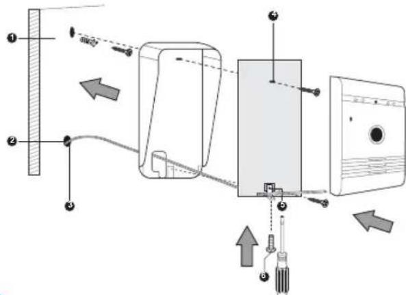
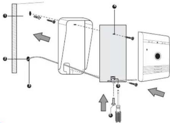
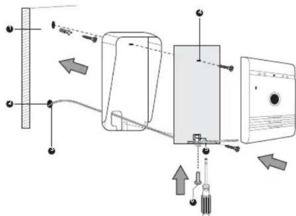
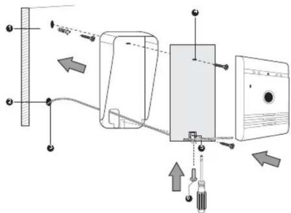
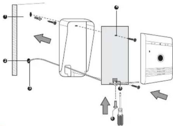
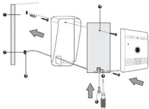
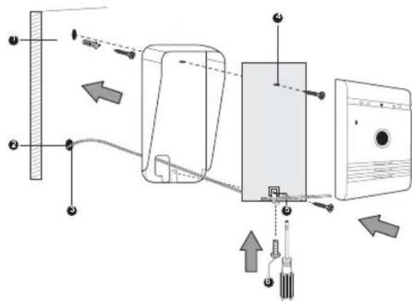
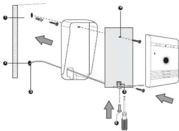
- Select the location for the Outdoor Intercom and using the rain cover as a template mark and drill the holes to allow the supplied wall plugs to be fitted. (fig 1)
- Also mark and drill the hole required for the power cables to go through the wall. (fig 2)
- Push the power cables from the inside of the wall so they are visible on the outside. (fig 3)
- Stick the sealing pad on the inside of the rain cover. (fig 4)
- Secure the rain cover into position using the fixings supplied. Pay attention to the angle bracket (fig 5) on the bottom fixing making sure the power cables are pushed through the back plate seal hole on the bottom right.
- Secure the power cables into the Intercom as per the wiring diagrams below.
- Insert the intercom top first into the rain cover and put the bottom into position over the angle bracket.
- Secure the intercom into position on the rain cover using the securing screw. (fig 6)
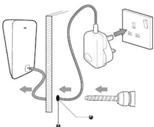
Outdoor Intercom
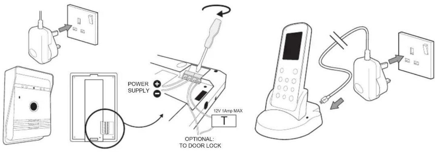
- Connect the DC power supply to the terminals marked + & - making sure the wires are installed the correct way around (See image above).
- If required connect the door lock cables to the 2 terminals making sure a suitable power supply is used to power the door lock.
(Items DB5005 and DB5005L - Not supplied)
Indoor Monitor
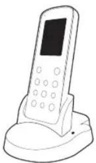
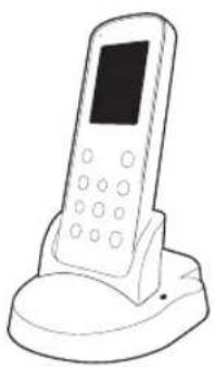
- Connect the USB lead to the Indoor Monitor base, plug the adaptor into a wall outlet and switch the wall outlet ON.
PAIRING
- Press the power Ⓘ button (11) to turn on the screen.
- Hold the ↕ button (3) for 3 seconds and the screen will display "pairing".
- Press the CALL button (4) once on the Outdoor Intercom to turn it on.
- HOLD the CALL button (4) for 10 seconds on the Outdoor Intercom.
- "Success" will be displayed on the Monitor to indicate pairing is complete.
- If pairing did not work then "fail" will be displayed, please repeat step 2, 3 + 4 again.
SCREEN ICONS
Outdoor Intercom
- When a visitor presses the call button (4) of outdoor intercom, the indoor monitor will give a bell tone and activate the monitor screen. The indoor monitor screen will display a picture of the visitor automatically.
- Press the Intercom ↗ button (3) and speak to the visitor.
- Press the Exit ← button (4) to end the call and the screen will switch to standby mode.
Indoor Monitor:
- The Monitor/Delete 📋 button (7) can be used to see who is at the door when the Outdoor CALL button has not been pressed. (Only available when outdoor intercom is mains powered.)
- Press the Intercom ↗ button (3) and speak to the visitor.
- Press the Exit ← button (4) and the screen will switch to standby mode.
Unlock:
- After identifying the visitor press the Unlock button (10) to unlock the door. (Only for operation with an electric door opener MAX 12v 1A using separate power supply - Items DB5005 and DB5005L - Not supplied.)
Photograph
- When a visitor presses the call (4) button of the Outdoor Intercom the Indoor Monitor will automatically take a photo.
- On the Indoor Monitor press the Photo/Confirm 📷/← button (12) and it will take an extra photo of the visitor.
View / delete photo:
- On the Indoor Monitor press the Playback/Set ☐/button (14) to enter the picture menu.
- Press the Up ▲(5) or Down ▼(8) buttons to view the stored photo.
- Press the Monitor/Delete 📋/☐(7) button to enter delete dialog box.
- Press the Left ◀(6) or Right ▶(13) button to select Yes / No.
- Press the Photo/Confirm 📷/←(12) button to confirm.
- Press the Exit ← (4) button to exit.
To delete all photos:
- On the Indoor Monitor press the Playback/Set ☐/button (14) to enter the picture menu.
- Hold the Monitor/Delete 📄/☐(7) button for 3 seconds and "delete all" will appear.
- Press the Left ◀(6) or Right ▶(13) button to select Yes / No.
- Press the Photo/Confirm 📷/← (12) button to confirm.
- Press the Exit ← (4) button to exit.
Setting the time / Date:
- Hold down the Playback/Set ☐/button (14) for 3 seconds to enter the main menu.
- Press the Up ▲(5) or Down ▼(8) buttons to move through the menu options to time/date.
- Press the Photo/Confirm 🔊/←button (12) to enter the submenu.
- Press the Up ▲(5) or Down ▼(8) buttons to adjust the settings.
- Press the Left ◀(6) or Right ▶(13) button to move through the time/date options.
- Press the Photo/Confirm 🔔/←button (12) to save and exit.
- Press the Exit ← (4) button to exit.
Adjust the Monitor brightness:
- Hold down the Playback/set ☐/button (14) for 3 seconds to enter the main menu.
- Press the Up ▲(5) or Down ▼(8) buttons to move through the menu options to brightness.
- Press the Photo/Confirm 📷/← button (12) to enter the submenu.
- Press the Up ▲(5) or Down ▼(8) buttons to select the level.
- Press the Photo/Confirm ↻ button (12) to save and exit.
- Press the Exit ← (4) button to exit.
Adjust the ring volume:
- Hold down the Playback/Set ☐/💡 button (14) for 3 seconds to enter the main menu.
- Press the Up ▲ (5) or Down ▼ (8) buttons to move through the menu options to volume.
- Press the Photo/Confirm 📷/← button (12) to enter the submenu.
- Press the Up ▲ (5) or Down ▼(8) buttons to select the level.
- Press the Photo/Confirm 🔔/← button (12) to save and exit.
- Press the Exit ← (4) button to exit.
Setting the bell tone:
- Hold down the Playback/Set ☐/button (14) for 3 seconds to enter the main menu.
- Press the Up ▲(5) or Down ▼(8) buttons to move through the menu options to chime.
- Press the Photo/Confirm 🔊/◀ button (12) to enter the submenu.
- Press the Up ▲(5) or Down ▼(8) buttons to select the tone.
- Press the Photo/Confirm 📄/← button (12) to save and exit.
- Press the Exit ← (4) button to exit.
RANGE GUIDE
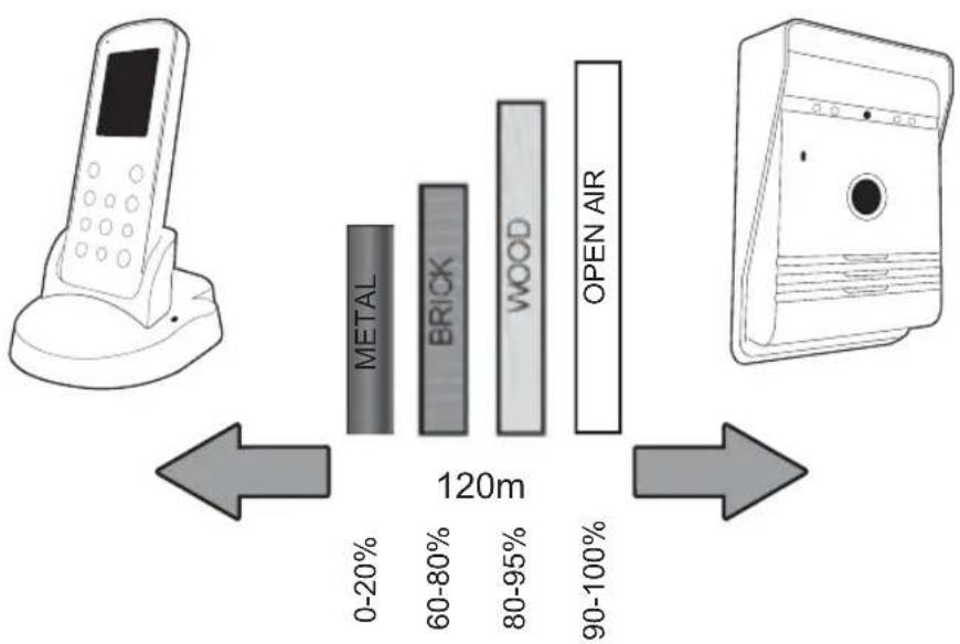
Test the chime before drilling any holes to ensure unit is within operating range. Wire-free range is affected by some materials/structures. Test prior to installation.
SPECIFICATION
| Operating Frequency 2400-2483.5MHz | |
| Transmission rate 15-25fps (only for effective distance) | |
| Open field operating range 120m | |
| TX power 14 – 18dBm | |
| RX sensitivity -85dBm | |
| Operating Temperature -10°C - +50°C | |
| Storage Temperature -20°C - +60°C | |
| Operating Humidity ≤85% RH | |
OUTDOOR CAMERA
| Image sensor type CMOS | |
| View Angle 55° | |
| Supply Voltage DC 5V 1A | |
| Consumption Current 250mA (± 50mA) | |
| Charging time Around 5 hours | |
| Battery 3.7v 1500mAh | |
| Adaptor | IP: 240v OP: 5v 1A |
INDOOR MONITOR
| Screen size | 2.4" |
| Resolution | 320 x 240 (RGB) |
| Supply Voltage DC 5V 1A | |
| Consumption current | 350mA ( ± 50mA) |
| Charging time Around 5 hours | |
| Image format | JPEG |
| Battery 3.7v 1200mAh | |
| Adaptor | IP: 240v OP: 5v 1A |
PRECAUTION
Do not cover the ventilation openings with objects such as newspaper, table cloths, curtains, etc.
Do not allow this product to get directly into contact with heat sources or naked flames.
√ The normal operation of the product may be disturbed by strong electro-magnetic interference.
√ This equipment is built exclusively for a domestic use.
√ The device must not be exposed to splashes and it must not be submerged.
No object containing liquids, such as a vase, may be placed on the device.
√ Maintain a minimum safety distance of 10cm all around the product in order to insure proper ventilation.
√ Insure the doorbell push button is not installed where it may be covered by water or rain.
Do not allow children to play with the device.
WARNING ABOUT BATTERIES
√ Only an adult may replace and install batteries.
√ Remove used batteries from this device.
Do not dispose of batteries in fire, they may explode or leak.
Do not short-circuit battery terminals.
√ DO not use any other type of battery other than the rechargeable pack supplied or similar.
Do not allow this device to get directly into contact with heat sources or flames.
Do not allow water to enter into contact with the batteries or the wires.
√ Install with caution to avoid damaging the batteries.
During battery installation in their compartment, insure proper polarity (+)/ (-).
√ Only use recommended batteries.
√ Remove the batteries if the device remains unused for long periods.
√ Keep the device away from small children.
√ Keep the unused batteries in their original packaging.
√ At the end of its life, this product must be returned to a waste processing center in order to extract the batteries.

Conforms to all relevant European Directives.
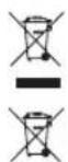
These symbols indicate that this product must not be disposed of with other household rubbish in the EU. In order to avoid all damage to the environment or to human health with rogue disposal responsibly recycle this product in order to encourage reuse of the materia resources. To return you used device, please use collection and return systems, or contact the dealer where you bought this product. He will take the product in order to protect the environment.
Smartwares declares that the appliance, model [VD36W], complies with the main essential requirements of the R&TTE directive, 1999/5/CE. The complete declaration of conformity is available on request at:
| smartwares'Europe | NL: 088 5940501 Lokaal tarief |
| BE: 078 481094(NL) Lokaal tarief | |
| BE: 078 481540(FR) Tarif local | |
| Jules Verneweg 875015 BH TilburgThe Netherlands | FR: 0825 560 650 18ct/min |
| DE: +49 (0) 1805 01076214Ct./Min. dt. Festnetz,Mobil max, 42Ct./Min | |
| service.smartwares.eu | UK: +44 (0) 345 230 1231ES: +34 938427589 |
WANRNHINWEISE
WANDMONTAGE
Außengerät
- When a visitor presses the call (4) button of the Outdoor Intercom the Indoor Monitor will automatically take a photo.
- On the Indoor Monitor press the Photo/Confirm 📷/← button (12) and it will take an extra photo of the visitor.
Setting the bell tone:
VORSICHTSMASSNAHMEN
WANDMONTAGE
Buitenintercom
VOORZORGSMAATREGEL
WAARSCHUWINGEN OVER BATTERIJEN
MONTAGE MURAL
CÂBLAGE
PRÉCAUTION
CABLEADO
PRECAUCIÓN
Citofono esterno
PRECAUZIONE
MONTAŻ NAŚCIENNY
OKABLOWANIE
Zewnętrzny interkom
ŚRODKI OSTROŻNOŚCI
Vnější přístroj
PREVENTIVNÍ OPATŘENÍ
- Högtalare
- Batteribox
- Likström in
- Utomhus batteriladdare
UTOMHUS-INTERCOM
VÄGGMONTERING
KABELDRAGNING
Utomhus-intercom
FÖRSIKTIGHETSÅTGÄRDER
DUVARA MONTAJ
Zewnętrzny interkom
TEDBIR

- VD36W
- INCLUDED IN THE PACK
- INDOOR MONITOR
- OUTDOOR INTERCOM
- BATTERY INSTALLATION
- WALL MOUNTING
- PAIRING
- SCREEN ICONS
- UNLOCK
- PHOTOGRAPH
- VIEW / DELETE PHOTO
- TO DELETE ALL PHOTOS
- SETTING THE TIME / DATE
- ADJUST THE MONITOR BRIGHTNESS
- ADJUST THE RING VOLUME
- SETTING THE BELL TONE
- RANGE GUIDE
- PRECAUTION
- WARNING ABOUT BATTERIES
- WANRNHINWEISE
- WANDMONTAGE
- AUSSENGERÄT
- VORSICHTSMASSNAHMEN
- BUITENINTERCOM
- VOORZORGSMAATREGEL
- WAARSCHUWINGEN OVER BATTERIJEN
- MONTAGE MURAL
- CÂBLAGE
- PRÉCAUTION
- CABLEADO
- PRECAUCIÓN
- CITOFONO ESTERNO
- PRECAUZIONE
- MONTAŻ NAŚCIENNY
- OKABLOWANIE
- ZEWNĘTRZNY INTERKOM
- ŚRODKI OSTROŻNOŚCI
- VNĚJŠÍ PŘÍSTROJ
- PREVENTIVNÍ OPATŘENÍ
- UTOMHUS-INTERCOM
- VÄGGMONTERING
- KABELDRAGNING
- FÖRSIKTIGHETSÅTGÄRDER
- DUVARA MONTAJ
- TEDBIR
Brand : SMARTWARES
Model : 10.008.92
Category : Intercom