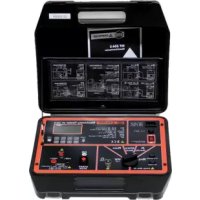
MT204S - Industrial test device Beha-Amprobe - Free user manual and instructions
Find the device manual for free MT204S Beha-Amprobe in PDF.



User questions about MT204S Beha-Amprobe
0 question about this device. Answer the ones you know or ask your own.
Ask a new question about this device
Download the instructions for your Industrial test device in PDF format for free! Find your manual MT204S - Beha-Amprobe and take your electronic device back in hand. On this page are published all the documents necessary for the use of your device. MT204S by Beha-Amprobe.
USER MANUAL MT204S Beha-Amprobe
MT204-S Machinery Tester
Users Manual



MT204-S Machinery Tester
Users Manual
Limited warranty and limitation of liability 6
Service 6
References marked on the instrument or in this instruction manual ... 7
Introduction 8
The following features characterise the Machinery-Tester MT 204-S .. 8
Scope of supply 9
Transport and storage 9
Safety measures 10
Appropriate usage 11
Operation elements and connectors 12
Front panel of the Machinery-Tester MT 204-S 12
Instrument cover 12
LC-Display 14
Safety measures 15
Preparation of the Machinery-Tester MT 204-S 16
Turning on the Machinery-Tester MT 204-S 16
Test lead compensation 16
Limit value setting 17
External voltage display, display in case of blown fuse 18
Automatic start and save function 18
Measurement according to EN 60204-1 19
Earth bond resistance measurement (RPE function) 19
Loop impedance / Prospective short-circuit current measurement (ZI/IPsc function) 20
Insulation resistance measurement (Riso function) 22
High voltage test (HV function) 24
Residual voltage / Discharge time measurement (URES, tRES function) 26
Explanation of linear and non-linear mode 28
Residual voltage measurement "Linear mode" 28
Residual voltage measurement "Non-linear mode" 29
Trigger conditions 29
Menu functions 30
General operation instructions 30
"MEMORY" menu 31
"DATE/OPERATOR" menu 32
"LANGUAGE" menu 33
"CONTRAST" menu 33
"BACKLIGHT" menu 34
"TESTER INFO" menu 34
Memory features 35
Memory structure 35
General memory operations 36
Memorizing example 37
Recall data 38
Entry of memory address using external keyboard 39
Enter of memory address using bar code reader 40
Maintenance 41
Cleaning 41
Calibration interval 41
Fuse replacement 41
Fuse replacement (mains fuse F1) 42
Fuse replacement (fuse F2 for RPE10A, ZI, RISO and HV functions) .... 42
Fuse replacement (fuse F3 for RPE0.2A function) 43
Technical data 44
General data 44
Measurement functions 45
Limited warranty and limitation of liability
It is guaranteed that this BEHA-AMPROBE product is free of material and manufacturing damages for the time period of 24 months starting from the date of purchase. This warranty does not include fuse malfunctions, as well as damages caused by accidents, negligence, misuse, unauthorised modifications, abnormal operating conditions or improper handling. The sales offices do not have the right to extend the warranty on behalf of BEHA-AMPROBE.
Service
All instruments that are sent in for repair or calibration within or beyond the warranty period, must contain the following data: Name of the client, name of the company, address, contact telephone number and a proof of purchase. Please enclose also the test leads and a short description (or a service form) of the problem detected or of desired maintenance.
Amprobe Test Tools Europe
BEHA-AMPROBE GmbH
In den Engematten 14
79286 Glottertal
Germany
Tel.: +49 (0) 7684 8009 - 0
Fax: +49 (0) 7684 8009 - 410
www.amprobe.eu
info@amprobe.eu
References marked on the instrument or in this instruction manual
| Warning of a potential danger, comply with instruction manual. | |
| Reference, please pay utmost attention. | |
| Caution, dangerous voltage. Danger of electrical shock. | |
| Symbol for marking of electrical and electronic equipment (WEEE Directive). | |
| CE | Conformity symbol, the instrument complies with the valid directives. It complies with the EMC Directive and the Low Voltage Directive. |

- The instruction manual contains information and references, necessary for safe operation and maintenance of the instrument. Prior to using the instrument, the user is kindly requested to thoroughly read the instruction manual and comply with it in all sections.
- Failure to read the instruction manual or to comply with the warnings and references contained herein can result in serious bodily injury or instrument damage.
Introduction
You have acquired a high-quality measurement instrument manufactured by BEHA-AMPROBE GmbH, which will enable you to perform repeatable measurements for a very long period of time.
The Machinery-Tester MT204-S is a measurement instrument used for final inspection and documentation of electrical equipment of machines, control cabinets, switchgears as well as devices complying with EN 60204-1.
The following features characterise the Machinery-Tester MT 204-S:
- Earth bond resistance measurement with 10 A AC or 0.2 A AC
- Loop / Mains impedance measurement up to 440 V
- Display of prospective short circuit current
Insulation resistance measurement with 500V DC, available also adjustable test voltage from 250...500 V DC
High voltage test with 1000V AC, 50 Hz - Residual voltage measurement and discharge time
- Easy operation using the rotary switch and the START/STOP button
Automatic start and save function for earth bond resistance and loop impedance allow both-hands measurements on measured objects that are difficult to access
Data memory for approx. 2000 measurement results - Integrated interface (USB 2.0) for transfer of measurement results to PC
- Separate interface (USB 2.0) for connection of USB barcode reader, USB keyboard or USB memory stick
- Graphic LC-Display for measurement values, limit values and test parameters
- Compact housing with accessory compartment
- Connection diagrams and limit values under the instrument cover
- One pair of sockets and test leads only for all measurement functions
- Compensation of test lead's resistance for earth bond resistance and loop impedance measurement
- High-voltage test can be locked by using the protection key switch, operation available for properly instructed persons only
High-voltage test with adjustable breaking current
Scope of supply
1 pc Machinery-Tester MT 204-S
1 pc HV function lock key
1 pc Mains cord (Schuko)
1 pc Mains cord (Swiss)
1 pc Mains cord (UK)
2 pcs Safety test leads 2m
2 pcs Safety test lead extensions 10m
2 pcs Alligator Clips
1 pc USB interface cable
1 pc CD with USB drivers and instruction manual
1 pc Instruction manual in English/German/French/Italian/Spain
Optionally we offer test report forms and professional PC software for quick and easy creation of final test reports complying with EN 60204-1.
Available accessories:
PC Software for creation of test reports "es control prof"
USB Bar code reader
USB Keyboard
For leakage current measurement:
Current clamp AC50A, measuring range 0,01 A ... 60 A
Leakage current clamp with harmonic measurement CHB 5, measuring
range 0,05 mA...50 A
Transport and storage
Please keep the original packaging for potential later transport, e.g. for calibration. Any transport damage due to faulty packaging will be excluded from warranty claims.
Instruments must be stored in dry and closed areas. In case of an instrument being transported in extreme temperatures, a recovery time of minimum 2 hours is required prior to instrument operation.
Safety measures
The Machinery-Tester MT 204-S has been built and tested in compliance with the valid safety regulations and left the factory in safe and perfect condition. In order to maintain this condition and to ensure safe instrument operation, the user must pay attention to the references and warnings contained within this instruction manual.

WARNING, DANGER OF ELECTRICAL SHOCK
- In order to avoid electrical shock, the valid safety and national regulations regarding excessive contact voltages must receive utmost attention when working with voltages exceeding 120V (60V) DC or 50V (25V) RMS AC. The values in brackets are valid for limited ranges (as for example medicine).
- The respective accident prevention regulations established by the professional associations for electrical systems and equipment must be strictly met at all times.
- Prior to any operation, ensure that test leads used, mains cable and accessories are in perfect condition.
- The instrument may only be connected to mains voltage as indicated on the type shield.
- The instrument may only be used within the operating ranges as specified in the technical data section.
- Only touch test leads and test probes at handle surface provided. Never directly touch test probes.
- The instrument may only be used in dry and clean environments. Dirt and humidity reduce insulation resistance and may lead to electrical shocks, in particular for high voltages.
- Never use the instrument in precipitation such as dew or rain. In case of condensation due to temperature jumps, the instrument may not be used.
- A perfect display of measurement values may only be ensured within the temperature range of 0^ to +40^ .
- Prior to opening the instrument ensure that it is switched off and disconnected from all current circuits.
- To ensure a safe measurement only use original test leads and accessories.
- Dangerous voltages may be present at units under test caused by insulation test or high-voltage test. Do not touch the units under test, danger of electrical shock!
- Start any test series by earth bond resistance measurement.
- At insulation resistance, high-voltage and earth bond resistance measurement, unit under test must be voltage-free. If necessary check the unit is voltage-free i.e. by using a voltage tester.

HIGH VOLTAGE, DANGER OF ELECTRICAL SHOCK
-
The Machinery-Tester MT 204-S supplies high voltage of dangerous power. According to EN 50191 the following precautionary measures must be taken prior to a test:
-
Block access to danger area.
- Put up warning signs (Attention! High voltage, danger to life).
- Install warning lamps (red, green) to be easily visible.
- Install EMERGENCY-OFF switch into the mains installation outside the dangerous area.

These notes are just extracts of the EN 50191 standard. The following notes should be respected, when carrying out the measurements.
- Properly trained persons may only do the tests under supervision of specialized staff and have to be trained regularly.
- Use safety probes with protection against contact or with two-hand operation only. Always hold only one probe in one hand.
- Connecting one terminal to the test object and working with one probe or holding both probes in one hand is prohibited.
- It is prohibited to touch the unit under test during the test. If need be, additional measures must be taken (e.g. cover made of insulating mats) to protect the person performing the test against inadvertent contact with the unit under test.
- Testing may commence only after all safety measures were taken.
- To avoid any risk of use of high-voltage test function "HV" by unauthorized or not properly instructed personnel, the lock key must be removed from the key switch (6) when the device is not in use. The key can be removed in off position only, thus mechanically locking the high-voltage test function. Other measurement functions remain accessible.
Appropriate usage

WARNING
- The instrument may only be used under those conditions and for those purposes for which it was conceived. For this reason, in particular the safety references, the technical data including environmental conditions and the usage in dry environments must be followed.
- When modifying the instrument, the operational safety is no longer ensured.
- The instrument may only be opened by an authorised service technician. Before opening, the instrument must be switched off and disconnected from any electrical circuit.
Operation elements and connectors
Front panel of the Machinery-Tester MT 204-S
1 IEC connector for mains supply
2 Mains fuse (F1)
3 "ON/OFF" mains switch (with red pilot lamp)
4 Fuses for measurement functions RPE, RISO and HV (F2, F3)
5 Measurement function selector
6 HV lock key enabling / disabling the High-voltage test (flash test). The key can be removed in HV off position only. Dangerous high voltage will be applied to the output sockets (9) after pressing the "START/STOP" button (7).
7 Button "START/STOP" starts or stops the selected measuring function
8 Pilot lamp "ON" (white), measurement active
9 Output sockets for all measurement functions
10 Pilot lamp "1000 V" (red), high voltage test active
11 Eyelet for fastening the holding cord of the device cover
12 Keyboard with 4 function keys SAVE, RCL (recall), MENU, EXIT
13 USB interface for PC (USB1)
14 Keyboard with four menu keys. Function of these keys is adjusted to the actual function and can be seen in the bottom line of the LC-Display.
15 USB interface for USB barcode reader, USB keyboard or USB memory stick (USB2)
16 Graphic LC-Display for measurement values, limit values and parameters.
17 Front panel fastening screws (4 peaces)
Instrument cover
18 Brief instructions with limit values
19 Compartment for test leads and measurement accessories
Measurement accessories are stored in the compartment under the instrument cover. Instrument cover holds also a card with brief instructions and limit values according to EN 60204-1.
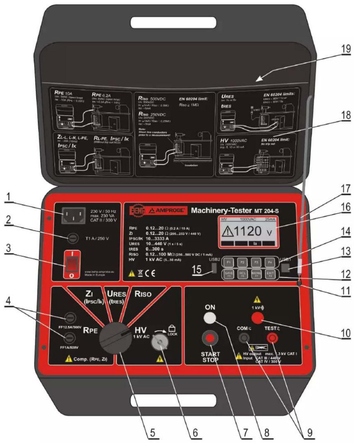
Figure 1: Machine Test MT 204-S
LC-Display
Display in a measurement function (e.g. RPE)
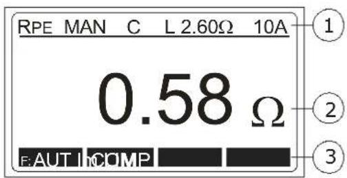
Figure 2: LC-Display in measurement function RPE
1 Line for display of measurement function, limit value and parameters
2 Display of measurement value and unit
3 Menu keys line
Menu display (after pressing the "MENU" key)
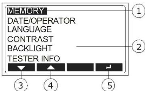
Figure 3: LC-Display "main menu"
1 Selected menu function
2 Other available menu functions
3 Menu key "▼" (down)
4 Menu key "▲" (up)
5 Menu key "」" (enter)
Safety measures
WARNING
- Correct functionality of the instrument must be verified prior to any use.
- Attention must be paid to proper condition of the test leads, measurement accessories and measurement instrument itself.
- Test leads and measurement accessories may only be touched on protected areas. Touching of conductive probes is prohibited at all times.
- The instrument may be used within specified measurement ranges only.
WARNING
- During measurement of earth bond and insulation resistance as well as during High-voltage test, the unit under test must be voltage-free and disconnected from mains voltage. In case of doubt, verify the voltage state by using a voltage tester.
- The instrument is protected against overload up to 440 Veff AC.
- Measurement input of the Machinery-Tester MT 204-S may be connected to max. 440V AC, pay also attention to overvoltage category CAT IV / 300 V, CAT III / 440 V!
- Measurement function selector must be set to required position prior to connecting test probes to the unit under test.
- Test leads must always be removed from the tested object before selecting a new function or another measurement range.
- Be aware that during measurement of earth bond resistance, contact resistances at the place of measurement affects the measurement result. Ensure good contact between the test probe (or crocodile clip) and the unit under test.
- Results of earth bond resistance measurements may be affected by impedances of additional operating current circuits connected in parallel or by equalizing currents.
- In the event that many loop impedance measurements are performed with only short breaks in between, the internal protection against over temperature will respond and the display "HOT, WAIT!" will appear. Next measurement cannot start until the instrument is cooled down (approx. 5 minutes). This protects the instrument against damage.
Preparation of the Machinery-Tester MT 204-S
Turning on the Machinery-Tester MT 204-S
1) Connect the Machinery-Tester MT 204-S to correctly installed schuko mains socket using supplied mains cord.
2) Use the mains switch "ON/OFF" (3) to turn on the MT 204-S.
3) After turning on the MT 204-S, pilot lamp of the power switch (3) will switch on and LC-Display (16) will show initial readout of selected function.
4) Connect both safety test leads (with touch protection) to MT 204-S test sockets (9).
5) The MT 204-S is now ready for use.
Test lead compensation
1) Set the measurement function selector (5) to RPE position.
2) Connect both test probes to each other. If need, use enclosed crocodile clips or measurement extensions.
3) Start the measurement by pressing the "START/STOP" button (7). Pilot lamp "ON" (8) indicates active measurement.
4) Stop the measurement by pressing the "START/STOP" button again.
5) Press the "COMP" menu key (14). Displayed value is saved as a compensation value and turns to 0.00. In the upper display line sign "C" (compensated) appears as a note test leads are compensated.

Figure 4: Measurement function RPE with compensated test leads
The compensation is respected in all further measurements in both functions RPE and ZI. Compensation value is saved also after the measurement instrument had been switched off.
Limit value setting
This function is available in measurement functions RPE, ZI and RISO.
For limit value setting press the "LIM" menu key (14), then use the "+" and "-" menu keys to set appropriate limit value.
The "EXIT" function key shall be used to exit limit value setting display.
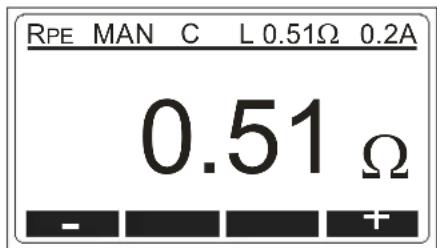

Figure 5: Limit value setting
In case test result comply with set limit value, there are two short sound signals present after finishing the measurement. In case of noncompliance, there is a corresponding warning symbol displayed accompanied with one longer sound signal after finishing the measurement. The limit value is saved as a parameter of the measurement result and is transferred to PC in case of data transfer.
External voltage display, display in case of blown fuse
- If there is an external voltage present at test tips in RPE, RISO or HV functions prior to a measurement, the "VOLTAGE" sign appears on the display and start of the measurement is blocked.
- If there is an external voltage applied to test tips after starting the RPE 10A measurement or if there is an over-voltage applied in ZI or HV function, fuse F2 may blow. The sign " (FUSE F2) 12.5A" appears on the LC-Display.
- If there is an external voltage applied to test tips after starting the RPE 0.2A measurement, fuse F3 may blow. The sign " (FUSE F3) 1A" or " (FUSE F2/F3)" appears on the LC-display.
- If an external voltage is applied to test tips during the measurement in RISO function, wrong measurement values may be displayed.
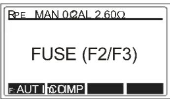
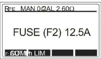
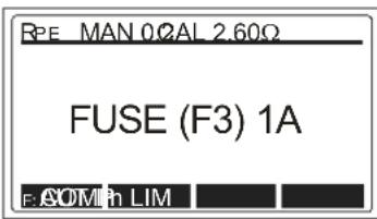
Figure 6: Display in case of blown fuse
Automatic start and save function
The Machinery-Tester MT 204-S has an automatic start and save function for earth bond resistance and loop impedance measurements. It can be used by pressing the "F:AUT" menu key.
The measurement starts automatically 1 s after test leads are connected to the unit under test and stops automatically after measurement result is achieved. The result is then automatically stored to preset memory address.
- Automatic start and save function enable both-hands measurement without pressing the "START/STOP" button. It shall be used especially on measurement objects that are difficult to access.
- Before using the automatic measurement, memory address (customer, machine and location), as well as the date and operator's name must be set/entered, so that the measurement value can be stored correctly.
Measurements according to EN 60204-1
Earth bond resistance measurement (RPE function)
- Complying with EN 60204-1, continuity of protective bonding circuit between PE terminal and relevant points of the protective conductor system must be checked by injecting a measurement current of 0.2A up to approx. 10A .
- Limit values are the values which correspond to the length, cross section and material of measured conductor.
1) Set the measurement function selector (5) to RPE position.
2) Select measurement current 10 A or 0.2 A by using the "Im" menu key (14).
3) For limit value setting press the "LIM" menu key (14). The limit value can be set by using the "+" and "-" menu keys.
4) Connect test probes (or crocodile clips) to the unit under test.
5) Start the measurement by pressing the "START/STOP" button (7), or select automatic start and save function by pressing the "F:AUT" menu key (14).
6) Pilot lamp "ON" (8) indicates active measurement.
7) Read displayed result considering appropriate limit value.
8) Stop the measurement by pressing the "START/STOP" button again.
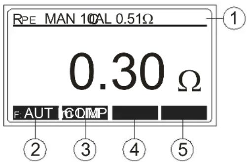
Figure 7: Measurement function RPE
1 Display of measurement function, test lead compensation mark, set limit value and parameters.
2 "F: AUT" / "F: MAN" menu key, for selection of automatic / manual start and store function
3 "COMP" menu key, for test leads compensation
4 "Im" menu key, for selection of test current (10 A or 0.2 A)
5 "LIM" menu key, for limit value setting
- To save displayed measurement result, press the "SAVE" function key (12) twice, for further instructions see the "Memorizing example" section.
Loop impedance / Prospective short-circuit current measurement (ZI/IPSC function)
- According to EN 60204-1, the conditions for protection against electric shock in installations with automatic disconnection of mains voltage are:
- Measurement or evaluation of fault loop impedance and testing the over-current protection device involved in the fault loop.
- Limit values are shown in the Table 10 of EN 60204-1.
1) Set the measurement function selector (5) to Zl position.
2) Use the "Im" menu key (14) to select appropriate measurement current (20 A or LOW).
3) For limit value setting press the "LIM" menu key (14). The limit value can be set by using the "+" and "-" menu keys.
4) Connect test probes (or crocodile clips) to the unit under test, present voltage will be displayed. If the value is within specified range, the sign "READY" appears on the LC-display.
5) Start the measurement by pressing the "START/STOP" button (7), or select automatic start and save function by pressing the "F: AUT" menu key (14).
6) Pilot lamp "ON" (8) indicates active measurement.
7) Read the displayed result considering the appropriate limit value.
8) For display of short circuit current press the "IPsc" menu key (14).
9) Stop the measurement by pressing the "START/STOP" button again.
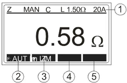
Figure 8: Measurement function ZI
1 Display of measurement function, parameters, test lead compensation mark and set limit value
2 "F: AUT / F: MAN" menu key, for selection of automatic / manual start and store function
3 "Z/IPsc" menu key, for selection of loop impedance or short circuit current function
4 "Im" menu key, for selection of measurement current 20 A or LOW
5 "LIM" menu key, for limit value setting
- For saving displayed measurement result press the "SAVE" function key (12) twice, for further instructions see the "Memorizing example" section.
- By setting the test current to 20A , the loop impedance measurement will be executed quickly and accurately. Potential motor protection switch or residual current device (RCD) can be triggered during the measurement, because of high test current.
- By setting the test current to LOW, low test current is used, and the motor protection switch or RCD will not be triggered during the measurement. However, the measurement takes more time and the measurement range as well as resolution are reduced.
Insulation resistance measurement (RISO function)
- According to EN 60204-1, the insulation resistance between shorted active conductors of power circuit and the earth bonding system must be checked applying a test voltage of 500VDC . The limit value is 1M
- Ensure that all switches on the unit under test are closed in order to test all its components. For purpose of the measurement, all active conductors (L1, L2, L3, N) must be shorted.
1) Set the measurement function selector (5) to RISO position.
2) Use the "Uiso" menu key (14) to select the measurement voltage 500V or adjustable 250V 500V .
3) For limit value setting press the "LIM" menu key (14). The limit value can be set by using the "+" and "-" menu keys. It can be also set directly to 1 MΩΩ by pressing the "1MΩ" menu key.
4) Connect test probes (or crocodile clips) to the unit under test.
5) Start the measurement by pressing the "START/STOP" button (7).
6) Pilot lamp "ON" (8) indicates active measurement.
7) Read the displayed result considering the appropriate limit value.
8) Stop the measurement by pressing the "START/STOP" button again.
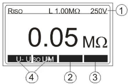
Figure 9: Measurement function Riso
1 Display of measurement function, parameters and limit value.
2 "Uiso" menu key, for selection of test voltage 500 V or adjustable 250 V...500 V
3 "LIM" menu key, for limit value setting
4 "U-" and "U+" menu keys for test voltage setting
- Due to the measurement of insulation resistance, capacitive units under test will be charged with test voltage.
The unit under test will be discharged after finishing the measurement via internal resistance of approx. 3M . The unit under test can retain dangerous voltage in case of premature removal of test leads. Ensure
that the unit under test is discharged through the measurement instrument (not through short circuit)!
- For saving displayed measurement result press the "SAVE" function key (12) twice, for further instructions see the "Memorizing example" section.
- Note! Connect COM test lead to chassis if the object under test is grounded. In case of reversed test leads, measurement result may be affected by instrument's internal resistance of 10M
High voltage test (HV function)
- According to EN 60204-1, electric equipment must withstand a voltage test between shorted active conductors of power circuit and the earth bonding system for approx. 1 s.
- The test shall be carried out at twice the rated supply (or 1000V whichever is greater) 50Hz . Components not rated for this test voltage may be disconnected before carrying out the test.

WARNING, DANGER OF ELECTRICAL SHOCK
The Machine tester MT204-S supplies high voltage of a dangerous power. According to EN 50191 the following precautionary measures must be taken prior to a test:
- Block access to danger area.
- Put up warning signs (Attention! High voltage, danger to life).
- Install warning lamps (red, green) to be easily visible.
- Install EMERGENCY-OFF switch into the mains installation outside the dangerous area.
- Electrical trained personnel may only do the tests under supervision of specialist staff and have to be trained regularly.
- Do not use crocodile clips for this test.
- Use safety probes with two-hand operation only. Always hold only one probe in one hand.
- Connecting one test terminal to the object under test and working with one probe or holding both probes in one hand is prohibited.
- It is prohibited to touch the unit under test during the test. If need be, additional measures must be taken (e.g. cover made of insulating mats) to protect the person performing the test against inadvertent contact with the test object.
Testing may commence only after all safety measures were taken.
Ensure that all switches on the unit under test are closed in order to test all its components. For the purpose of measurement all active conductors (L1, L2, L3, N) shall be shorted.
1) Release the HV measurement function by using the key switch (6) and by turning it counter-clockwise.
2) Set the measurement function selector (5) to "HV" position
3) Use the "It" menu key (14) and select appropriate trip current (5 50mA) , start with the minimum value of response.
4) Start the test by pressing the "START/STOP" button (7).
5) Make contact with two-hand use test probes to the unit under test.
6) Pilot lamp "ON" (8) indicates active measurement. Additionally a red pilot lamp "1000 V" (10) will switch on and an acoustic sounds signals indicate active dangerous high voltage present at test tips.
- In case of flashover in the unit under test, the test is terminated immediately, both pilot lamps (8) and (10) switch off and the "FAIL" mark is displayed.
7) Stop the test by pressing the "START/STOP" button again.
- After finishing the high-voltage test, set the measurement function selector (5) to any function but "HV" and lock the HV function against unauthorized use by removing the lock key!
- If the Machinery-Tester MT 204-S is, in mean time, switched off or disconnected from mains, the sign "HV LOCKED!" appears on the LC-Display after pressing the "START/STOP" button. Measurement function selector has to be turned out of the "HV" position and in again.
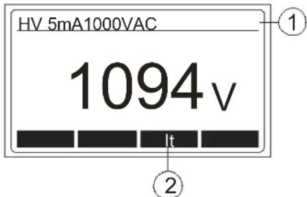
Figure 10: Measurement function HV
1 Display of measurement function and parameters
2 "It" menu key, for selection of tripping current
- For saving displayed measurement result press the "SAVE" function key (12) twice, for further instructions see the "Memorizing example" section.
Residual voltage / Discharge time measurement (URES, tRES function)
- What are residual voltages? Residual voltages are such voltages that exist even after switch off a machine or a device. This can be caused e.g. by built in capacitors or subsequent generators. This measurement is performed using the function "URES, tRES".
- According to EN 60204-1, accessible live parts connected to dangerous voltage must discharge within 5 seconds (permanently connected machines) or within 1 second (plugged-in machines) down to 60V . Proof of this must be given through tests.
- In the event of non-compliance, additional measures (discharge devices, warning information, covers etc.) according to EN 60204-1 must be taken.
- With the Machinery-Tester MT 204-S the residual voltage can be measured 1 s or 5 s after switching off tested machine. Measurement of residual voltage can be carried out in linear or non-linear mode, see the section Residual voltage "Linear mode" or section Residual voltage "Non-linear mode".
1) Set the measurement function selector (5) to URES position.
2) Use the "F: t" / "F: URES" menu key (14) to select the measurement function (Residual voltage or Discharge time).
3) In Residual voltage function use the "MODE" menu key (14) to select measurement mode "LIN" or "UNLIN" and "TIME" menu key to select measuring time (1 s or 5 s).
4) In Discharge time function use the "LIM" menu key (14) to select the limit value for discharge time (1s or 5 s).
5) Connect test probes (or crocodile clips) to the unit under test, select the accessible points where the residual voltage can cause danger (mains connection, touchable contacts, capacitors, active conductors etc.)
6) Start the measurement by pressing the "START/STOP" button (7).
7) Pilot lamp "ON" (8) indicates active measurement.
8) Turn on main ON/OFF switch on tested machine, the value of present voltage appears on the LC-Display. Once the voltage is stabilized "READY" mark appears on the LC-Display.
9) Turn off main ON/OFF switch on tested machine and wait measurement result to be displayed (Residual voltage or Discharge time), pay attention to corresponding limit values.
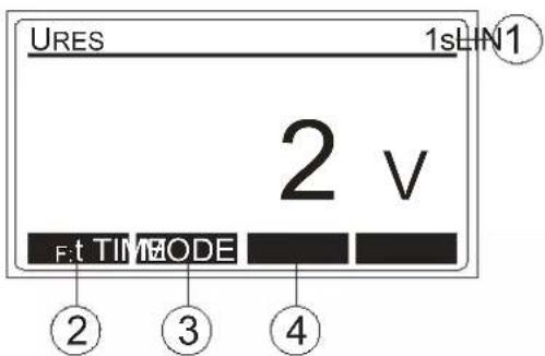
Figure 11: Measurement function URES
1 Display of measurement function, parameters and set limit value
2 "F: t / F: U" menu key, for selection of measurement function (Residual voltage or Discharge time)
3 "MODE" menu key, for selection of measurement mode "LIN" or "UNLIN".
4 "TIME" menu key, for selection of measurement time (1 s or 5 s)
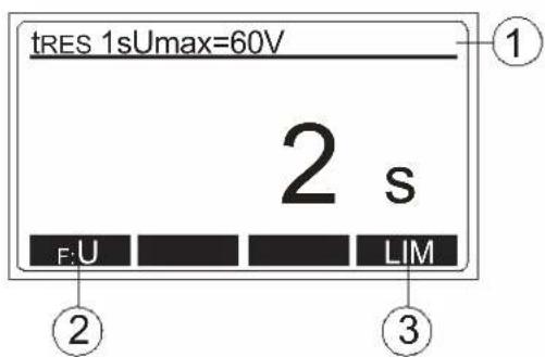
Fig 12: Measurement function tRES
1 Display of measurement function, parameters and limit value
2 "F: t/F: U" menu key, for selection of measurement function (Residual voltage or Discharge time)
3 "LIM" menu key, for selection of discharge time limit value (1 s or 5 s)
- For saving displayed measurement result press the "SAVE" function key (12) twice, for further instructions see the "Memorizing example" section.
- If in linear mode the mains voltage is disconnected at too low value (<20% of peak value), it means scaling of measurement result to peak value is not possible. In this case "REPEAT THE MEASUREMENT" message appears on the display and the measurement must be repeated.
Explanation of linear and non-linear mode
Residual voltage measurement "Linear mode"
In linear mode it is assumed there are only "linear" components involved in discharge process (capacitors, resistors, inductors etc.) and therefore discharge characteristic is exponential, see the diagram below.
In linear mode displayed result refers to peak value of mains voltage, see the figure 13.
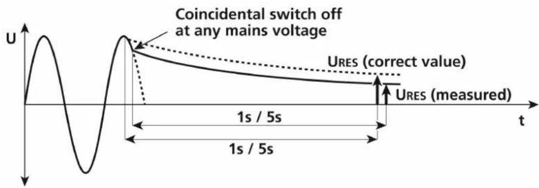
Figure 13: Linear mode
In linear mode the MT 204-S detects automatically two standard system voltages:
230V Uin = 230V± 10% 400V Uin = 400V± 10%
To include mains over-voltage, the measured residual voltage is calculated with reference to peak value of max. possible mains over-voltage, i.e.:
Up = 230V× 1.1× 1.41 = 358V standard system voltage 230V Up = 400V× 1.1× 1.41 = 620V standard system voltage 400V
If actual mains voltage differs from nominal system voltage more than ± 10% , the MT204-S scales the result to peak value of actual voltage.
Example 1: Uin = 173 Vef (the value differs more than 10% from 230V), result refers to 173V× 1.41 = 244Vp
Example 2: Uin = 209Vef , the value differs less than 10% from 230V , result refers to 230V × 1.1 × 1.41 = 358Vp
Residual voltage measurement "Non-linear mode"
In non-linear mode it is assumed there are also "non-linear" or unknown components involved in discharge process (relays, gas lamps etc.) and therefore discharge characteristic is non-exponential or even unpredictable, see the diagram below.
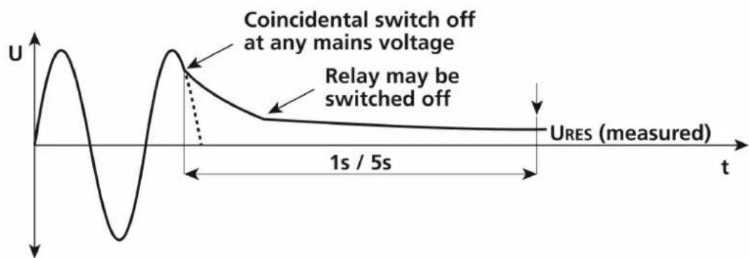
Figure 14: Discharge diagram in non-linear circumstances
In this case result can not be scaled to peak value, so actual value after the end of measuring time is registered and evaluated.
In this operation mode the measurement must be repeated several times to ensure the unit under test was tested under varying shut-off conditions. The highest measured value must be recorded.
Trigger conditions
The instrument recognizes disconnection of mains voltage when one of the following two conditions occurs:
- AC or DC input voltage: If mean value of input voltage drops down with a slope of at least 25V / s (mean value measured each period)
AC input voltage only: If momentary voltage differs from ideal sine waveform value more than 40% of peak value of previous half period (momentary voltage sampled 100 times per period)
- If in linear mode the mains voltage is disconnected at too low value (<20% of peak value), it means scaling of measurement result to peak value is not possible. In this case "REPEAT THE MEASUREMENT" message appears on the display and the measurement must be repeated.
Menu functions
For further selection, entry and display of instrument's settings, press the "MENU" function key (12), the following selection menu appears.
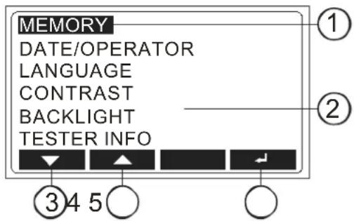
Figure 15: LC-Display "Main menu"
1 Selected menu function
2 Other available menu functions
3 "▼" menu key (down)
4 "▲" menu key (up)
5 " " menu key (Enter)
General operation instructions
- Use the "▼" and "▲" menu keys to select wished menu function then confirm it by pressing the "↓" key.
- Entered menu function may be aborted by pressing the "EXIT" function key (12).
- Inside selected submenu SAVE TO USB or CLEAR, a storage address is to be selected by using the "▲", "▶" and "▼" menu keys.
- By pressing the "REN" menu key, entered names (customer, machine, location) can be modified, use the < - menu key to erase previous characters.
- By pressing the " 一 ", selected function is activated.
"MEMORY" menu
In this menu the following selections are available:
| SAVE TO USB: | Transfer of stored data to USB memory stick. The whole storage, individual customer, machine, measurement location or only measurement result can be transferred. Data records to be transferred can be selected with the "▲", "▶" and "▼" menu keys and transfer action by pressing the "↓" menu key. |
CLEAR: Erasing of measurement results. The whole memory, individual customer, machine, measurement location or only measurement result can be erased. Data records to be erased can be selected by using the "▲", "▶" and "▼" menu keys, clear action must be confirmed by pressing the "←" menu key.
MEMORY PROPERTIES: Display of the number of occupied and free memory locations.
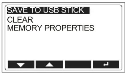
Fig 16: LC-Display menu "MEMORY"
- If in "CLEAR" menu the option "TOTAL" or "individual customer" or "individual machine" or "individual location" is selected, all data under selected address will be erased. Another security query takes place before final realization.
- USB memory stick shall be connected to USB interface USB2. Three sound signals will follow after plugging it to USB2 connector as a confirmation the memory stick is recognized by the Machinery-Tester MT204-S. The USB memory stick has to be FAT12, FAT16 or FAT32 formatted, sector size 512 Byte.
The data is written in a file that can be read by Software es control.
"DATE/OPERATOR" menu
There are the following selection possibilities:
DATE: Setting of actual date. Use the "▼", "▲" and "▶" menu keys to set the date then confirm it by pressing the "↓"
menu key.
OPERATOR: Entry of the operator. After date confirmation, the cursor is automatically placed to the last character of the operator's name. Modify / enter the name by using the "▼", "▲" and "←" menu keys then confirm it by pressing the "↓" menu
key.
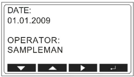
Figure 17: LC-Display menu "DATE/OPERATOR"
- The date and operator are attached to each measurement result automatically after finishing the measurement.
"LANGUAGE" menu
There are the following selection possibilities:
ENGLISH, GERMAN, FRENCH, ITALIAN or Spanish language.
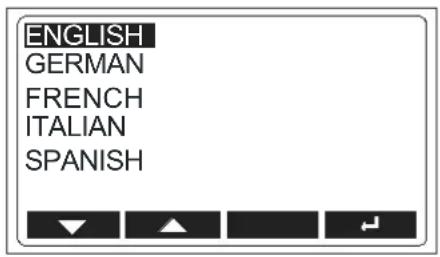
Figure 18: LC-Display menu "LANGUAGE"
"CONTRAST" menu
Contrast of the LC-Display can be adjusted by using the "-" and "+" menu keys.
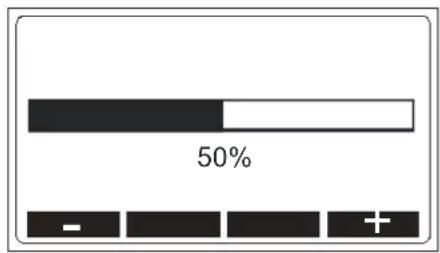
Figure 19: LC-Display menu "CONTRAST"
"BACKLIGHT" menu
Backlight of the LC-Display can be switched either off or on by using the "OFF" and "ON" menu keys.
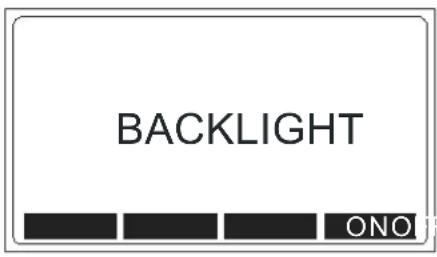
Figure 20: LC-Display menu "BACKLIGHT"
"TESTER INFO" menu
The following instrument information can be read in this menu: Model, Serial number, Catalogue number, Firmware version and Hardware version.
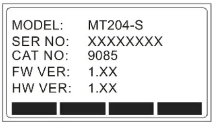
Figure 21: LC-Display menu "TESTER INFO"
Memory features
Any memory address consists of a customer name, machine name and location name. The memory address should be entered / selected before storing measurement results. Date and operator must be entered before carrying out the measurements as they are attached to any measurement result immediately after finishing the measurement.
Memory structure
Measurement result, limit value and parameters are saved to selected memory address upon receiving the SAVE command. The following structure of the memory address is offered:
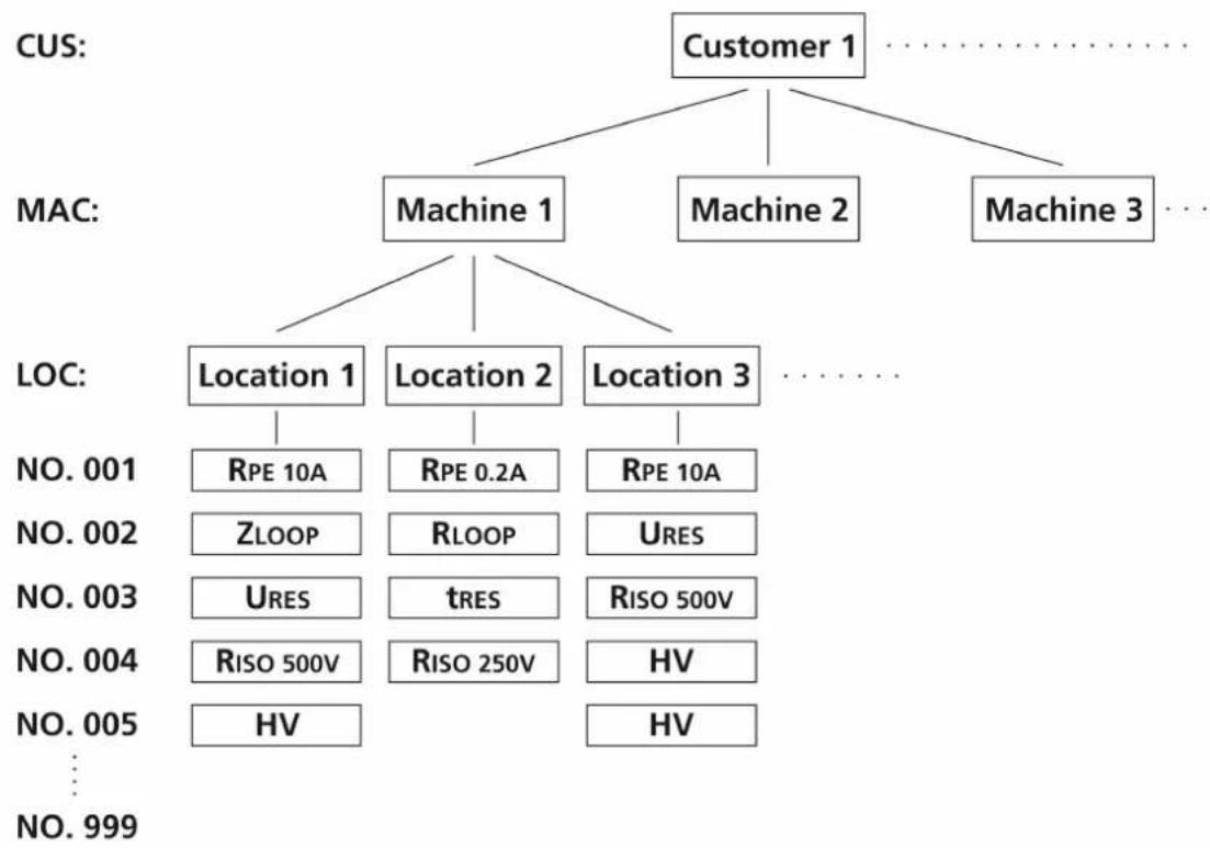
Figure 22: Storage structure
CUS: Customer (max. 17 characters)
MAC: Machine (max. 17 characters)
LOC: Location (max. 17 characters)
NO.: Measurement no. of the test within address "Location" (max. 3 fig.)
- The date and operator are attached to any measurement result automatically after finishing the measurement.
- In Software es control the field "CUS" (customer) is assigned to "Client" and the field "MAC" (machine) is assigned to "Appliance". The fields "LOC" (location) and "NO." (measurement number) are joint together, hyphenated and entered into column "Loc-No." to each test step.
General memory operations
Menu key "▼" Storage level (customer, machine, location,
No.) is selected.
Menu keys " " and " " Already entered names (for customer, machine, location, Nr.) can be selected. A new name can be opened by using the " " menu key.
Menu key "REN" Rename, already entered name can be modified.
Menu key 一 ^ 一 Individual characters are deleted.
Menu keys "▼" and "▲" Entry of characters, "A...Z, 0...9, +, -, /, #, and space" can be selected. Cursor moves to the next character automatically approx.
2 s after selecting previous one.
Menu key "」" Enter,entry is completed.
Function key "EXIT" Entry will be aborted.
Recall (RCL) Recall, in this menu it is possible to clear individual measurement by pressing the menu key "CLR".
- When entering fields for client, machine and location, alphanumeric characters (A...Z, 0...9), symbols (+, -, _/, #) and space are available.
- When selecting the "No." field (measurement number), numeric figures 001 up to 999 are available. The number is automatically increased by 1 for any next measurement to be saved.
- The measurement number "No." can be manually listed forward and backward. It is also possible to overwrite already saved measurement result.
- Default value for new names (clients, machine and location) is "XXXX".
Memorizing example
In order to save measurement result to a particular storage address follow the following instructions:
1) Carry out the measurement.
2) Press the "SAVE" function key (12).
3) Level "CUS" (customer) is already marked. Select already entered customer name by using the "< and " menu keys. If wished customer name is not entered yet, then setup a new customer by using menu key " ", offered default name is "XXXX". Press the "REN" menu key and delete default name "XXXX" by using the " " menu key.
4) Enter a new customer name for example "CUS001" by using the "▼" and "▲" menu keys. Confirm entry by pressing the "+" key.
5) Select the next storage level "MAC" (machine) by using the "▼" menu key.
6) Select already entered machine name by using the "▲" and "▶" menu keys. If wished machine name is not entered yet, then setup a new machine by using menu key "▶", offered default name is "XXXX". Press the "REN" menu key and delete default name "XXXX" by using the "←" menu key.
7) Enter a new machine name for example "MAC001" by using the "▼" and "▲" menu keys. Confirm entry by pressing the "+" menu key.
8) Select the next storage level "LOC" (location) by using the "▼" menu key.
9) Select already entered location name by using the and menu keys. If wished location name is not entered yet, then setup a new location by using menu key , offered default name is "XXXX". Press the "REN" menu key and delete default name "XXXX" by using the menu key.
10) Enter a new location name for example "LOC001" by using the "▼" and "▲" menu keys. Confirm entry by pressing the "↓" key.
11) Press the "SAVE" function key again to store the measurement result, memorizing is confirmed with double sound signal.
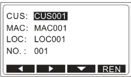
Figure 23: Memorizing address
- If already occupied storage address (customer, machine, location and serial number) is selected when storing measurement result, "BUSY" mark will appear on the LC-Display. Previously stored result will be overwritten after pressing the "SAVE" menu key.
Recall data
In order to recall stored measurement result follow the following instructions:
1) Press the "RCL" menu key (12).
2) Level "CUS" (customer) is already marked. Select wished customer name by using the <> and > menu keys.
3) Select the next storage level "MAC" (machine) by using the "▼" menu key. Select wished machine name by using the "▲" and "▶" menu keys.
4) Select the next storage level "LOC" (location) by using the "▼" menu key. Select wished location name by using the "▲" and "▶" menu keys.
5) Select the next storage level "NO." (measurement number) by using the "▼" menu key. Select wished measurement number by using the "▲" and "▶" menu keys.
6) Press the "RCL" function key (12) again to recall stored measurement result. Now it is possible to browse among all measurement numbers under selected storage address, by using the and menu keys.
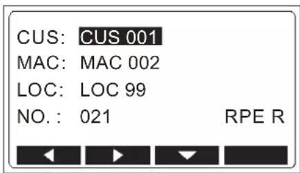
Figure 24: Recall address
- Individual recalled measurement results can be deleted by pressing the "CLR" menu key.
- Storage address with the last stored measurement result is offered always after activating "Recall" operation.
- If selected storage address is not occupied, "LOCATION EMPTY" appears on the LC-Display.
Entry of memory address using external keyboard
The optional USB keyboard is a welcome accessory when inserting memory address construction (customer, machine and location) in order to do the job quickly and simply. Connect the USB keyboard to USB2 connector, three sound signals follow after plugging it, as a confirmation of USB-device recognition. Now, the external keyboard is operational. The following keyboard keys are active to control the MT 204-S:
Table 1: Functions of the USB keyboard
| USB keyboard Function MT 204-S | |
| F1, F2, F3, F4 | Menu keys 1 to 4 (14) |
| F5, F6, F7, F8 | Function keys SAVE, RCL, MENU, EXIT (12) |
| Esc | Function key EXIT (12) |
| ENTER | Menu key " \( \neg \) " (14) |
| \( \downarrow ,\uparrow \) | Menu keys ▼, ▲ (14) |
| \( \leftarrow ,\rightarrow \) | Menu keys \( \leftarrow ,\triangleright \) (14) |
| A, B, C ... Z Entry of storage address | |
| 0, 1, 2 ... 9 | Entry of storage address |
| +,-,_,/,# | Entry of storage address, special symbols |
| Space | Entry of storage address, space |
| Pos 1 (Home) | Moves cursor to start position when entering memory address |
| Ende | Moves cursor to end position when entering memory address |
| ← | Deletes character left from the cursor when entering memory address |
| Entf | Deletes character at the cursor when entering memory address |
| + Menu key "+" (14) | |
| - Menu key "-" (14) | |
Entry of memory address using barcode reader
The optional USB barcode reader is a welcome accessory when inserting memory address structure (customer, machine and location) in order to do the job quickly and simply. Connect the USB barcode reader to USB2 connector, three sound signals follow after plugging it, as a confirmation of USB device recognition.
Connect the barcode reader to USB2 connector.
Storage address level (customer, machine or location) must be selected first by using the "▼" menu key, then scan can be done.
Maintenance
When using the instrument in compliance with the instruction manual, no special maintenance is required. However, should functional errors occur during normal operation, our after sales service will repair your instrument without delay.
Cleaning
If the instrument is needed to be cleaned after daily usage, it is advisable to use a wet cloth and a mild household detergent.
Prior to cleaning, remove the machinery tester from all measurement circuits and from mains.
Never use acid-based detergents or dissolvent liquids for cleaning.
After cleaning it, do not use the instrument until it is completely dried up.
Calibration interval
We suggest a calibration interval of one year. If the instrument is used very often or if it is used under tough conditions, we recommend shorter intervals. If the instrument is rarely used the calibration interval can be extended on to 3 years.
Fuse replacement
If, due to overload or improper operation, a fuse blows, it is necessary to obey the following notes for replacement:

Prior to replacement of blown fuse, the Machinery-Tester MT 204-S must be disconnected from all measuring circuits and mains supply cord must be removed.
- Use only fuses specified and rated in technical specifications.
- Use of unspecified fuses and in particular shorting fuse-holders is prohibited.
- Spare fuses can be obtained in electric supplies wholesale shops or in our factory service.
Fuse replacement (mains fuse F1)
In case mains switch pilot lamp (3) does not illuminate after connecting the Machinery-Tester MT204-S to mains outlet and switching on the mains switch and neither the LC-Display (16) shows any indication, it is very likely mains fuse (2) to be blown.
To replace the fuse proceed as follows:
1) Open the fuse holder 1 (2) above the ON/OFF switch by using an appropriate screwdriver
2) Remove the defective fuse and replace it with a new one (T 1 A / 250 V, 5 × 20 ~mm )
3) Close the fuse-holder again
Fuse replacement (fuse F2 for RPE10A, ZI, RISO and HV functions)
Internal fuse F2 (FF 12.5 A / 500 V, 6.3 × 32 ~mm ) has blown if:
- Text "FUSE (F2) 12.5A" appears on the LC-Display in RPE10A, RISO or HV function
- Measurement values in ZI function are very low (ZI lower than 0.05 or IPsc higher than 4.6kA )
- Check the fuse also if "FUSE (F2/F3)" appears on the LC-Display in RPE0.2A or RPE10A function
To replace the fuse proceed as follows:
1) Unlock corresponding fuse holder (4) by using an appropriate screwdriver
2) Remove the defective fuse and replace it with a new one (FF 12.5 A / 500 V, 6.3 × 32 ~mm ).
3) Lock the fuse holder again.
Fuse replacement (fuse F3 for RPE0.2A function)
Internal fuse F3 (FF 1.0 A / 500 V, 6.3 x 32 mm) has blown if:
- Text "FUSE (F3) 1.0A" appears on the LC-Display in RPE0.2A function
- Check the fuse also if "FUSE (F2/F3)" appears on the LC-Display in RPE0.2A or RPE10A function
To replace the fuse proceed as follows:
1) Unlock corresponding fuse holder (4) by using an appropriate screwdriver
2) Remove the defective fuse and replace it with a new one (FF 1.0 A / 500 V, 6.3 × 32 ~mm ).
3) Lock the fuse holder again.

If any fuse blows several times (for example in case of operating error) the instrument must be sent in to the service department in order to be checked.
Technical data
General data
| Display | Graphic LC-Display, 128 x 64 dots |
| Limit value display | Optic and acoustic |
| Limit value setting Within measurement range (in functions RPE, ZI and RISO) | |
| Memory Approx. 2000 memory locations, 3 levels (customer, machine, measurement location), additional measurement No. is created. | |
| Interface (USB1) | USB 2.0 device, USB interface to PC |
| Interface (USB2) | USB 2.0 host, for barcode reader, keyboard or USB memory stick |
| Requirements on USB | |
| memory stick | FAT12, FAT16 or FAT32 with a sector size of 512 Byte |
| Working temperature range refer to this range) | 0 to 40°C (accuracies given in technical data |
| Storage temperature range | -10°C ... +50°C |
| Allowed humidity range condensation) | 10% ... 85% relative humidity (without |
| Height above sea level | up to 2000 m |
| Mains power supply | 230 V ± 10%, 50 Hz |
| Max. power consumption 230 VA | |
| Installed fuses: | |
| Mains fuse (F1) | T1 A / 250 V, 5x20 mm |
| For functions | |
| RPE 10A, RISO, HV (F2) | FF12.5 A / 500 V, 6.3x32 mm |
| RPE 0.2A (F3) | FF1 A / 500 V, 6.3x32 mm |
| Constructed according to | EN 61010-1 / EN 61557 (parts 2, 3, 4) |
| Over-voltage category: | |
| Mains inlet | CAT II / 300 V |
| Measurement input | CAT IV / 300 V, CAT III / 440 V |
| Measurement output (HV) | CAT I / 1300 V |
Measurement input / output is isolated with basic insulation against ground. Maximal output voltage (open circuit, mains over-voltage) is 1300V .
| Degree of pollution | 2 |
| Protection class | 1 |
| IP protection | IP 40 |
| Dimensions (W × L × H) | 345 × 320 × 170 mm with handle |
| Weight | Approx. 7 kg |
Measurement functions
Earth bond resistance (RPE 10A)
Measurement range 0.12 ... 20.00 Ω
Display range 0.00 ... 20.00 Ω
Resolution 0.01 Ω
Accuracy ± (3% rdg. + 2 digits)
Test current approx.10 A AC (mains voltage 230V±
10% , standard test leads 2 × 2 ~m and external resistance 0.1
Test voltage (open circuit) approx. 5.5 V AC (floating)
Measurement principle Two-wire connection
Test lead compensation Up to 5.00 Ω by pressing the "COMP" key
Protection against ext. voltage Fuse F2
Earth bond resistance (RPE 0.2A)
Measurement range 0.12 ... 10.00 Ω
Display range 0.00 ... 10.00 Ω
Resolution 0.01 Ω
Accuracy ± (3% rdg. + 2 digits)
Test current >0.2 A AC
Test voltage (open circuit) approx. 5.5 V AC (floating)
Measurement principle Two-wire connection
Test lead compensation Up to 5.00 Ω by pressing the COMP key
Protection against ext. voltage Fuse F3
Loop impedance / Prospective short-circuit current (ZI/IPSC 20A)
Measurement range ZI 0.12 ... 20.00 Ω
Display range Z1 0.00 ... 20.00 Ω
Resolution 0.01 Ω
Accuracy ± (3% rdg. + 3 digits)*
Display range IPSC 10 A ... 40 kA
Calculation IPSC for 230V(+ / - 10%) IPSC = 230V / ZI
for 400V(+ / - 10%) IPSC = 400V / Z
outside above two ranges IPSC = Umeas/ ZI
Accuracy IPSC Depends on ZI accuracy
Voltage range 200 ... 440 V, 50 Hz
Test current approx. 20 ... 44 A, (internal load of 10
for 20 ms)
Loop impedance / Prospective short-circuit current (ZI / IPSC LOW)
Measurement range ZI 1.2 ... 9.9 Ω, 10 ... 500 Ω
Display range ZI 1.2 ... 9.9 Ω, 10 ... 500 Ω
Resolution ZI 0.1Ω,1Ω
Accuracy ZI ± (3% rdg. + 6 digits)*
Display range IPsc 0.4 A ... 191 A
Calculation IPSC for 230V(+ / - 10%) IPSC = 230V / ZI
outside above range IPsc = Umeas / ZI
Accuracy IPSC Depends on ZI accuracy
Voltage range 200 ... 253 V, 50 Hz
Test current approx. 100mA pulsed
(measurement time max. 10 s)
Measurement principle Two-wire connection
Test lead compensation Up to 5.00 Ω (in RPE function)
- Declared accuracy may be affected in case of capacitive loads connected to measured installation close to measurement location!
Voltage measurement (TRMS) at Loop impedance
Measurement range 10 ... 440 V, 50 Hz
Display range 10 ... 440 V
Resolution 1 V
Accuracy ± (2% rdg. + 2 digits)
Insulation resistance (RISO)
Measurement range 0.12 ... 9.99, 10.0 ... 49.9, 50 ... 100 MΩ
Display range 0.00 ... 9.99, 10.0 ... 49.9, 50 ... 100 MΩ
Resolution 0.01 MΩ, 0.1 MΩ, 1 MΩ
Accuracy ± (5% rdg. + 3 digits) 0.00 ... 20.0 MΩ
± (10% rdg.)20.1 100M
Test voltage (UN) 500 V DC or
adjustable 250 ... 500 V DC in 10 V steps
Test voltage tolerance -0% ... +25%
Test current (500 V range) >1 mA DC (at 500 kΩ load)
Test current (250 V range) >1 mA DC (at 250 kΩ load)
Short-circuit current <6 mA DC
Capacitive load ≤ 2 F in parallel with RINS
- RINS accuracy within technical
specifications (RINS up to UTEST NOM /
1 mA) according to standard
- RINS accuracy within technical
specifications + additional 10% rdg
(RINS higher than UTEST NOM / 1 mA)
Discharge Internal resistance of 2.3 MΩ
(after finishing the measurement)
Note: COM terminal is connected to PE with an impedance of approx. 10M
High voltage test (HV)
Test voltage (UN) 1000 V AC, 50 Hz (floating)
Open-circuit test voltage 1000 up to 1300V AC (230V± 10%)
Accuracy of disp. test voltage ± (3% rdg.)
Output power 50 VA max.
Short-circuit current 0.4 A approx.
Breaking current (lt) Selectable 5mA 10 mA,25 mA or 50 mA
Accuracy of trip current ± 15% of It
Breaking time after reaching
breaking current < 20 ms
Residual voltage / Discharge time (URES, tRES)
Input voltage range 0 ... 440 V AC, 50 Hz
0 ... 622 V DC
Measurement range URES 10 ... 622 VDC or 10 ... 440 VAC
Accuracy URES (general) ± (2% rdg. + 2V)
Accuracy (LIN mode, AC input) - 0 V ... + 15 V
Measurement range tRES 0.8 ... 300.0 s
Display range tRES 0.0 ... 300.0 s
Accuracy tRES ± (2% rdg. + 2 digits)
Measurement trigger Automatic, see the chapter "Trigger conditions"
Input resistance 20 MΩ
Measurement time (limit value) Selectable 1s or 5s
Residual voltage limit value 60 V DC
Tolerance URES +0V -6V
Subject to technical changes without notice!
04/2010
PAEB90850000

MT204-S Machinery Tester
Bedienungsanleitung
April 2010, Rev. 2, 10/23
©2010-2023 Beha-Amprobe.
All rights reserved.
Software es control professional
tRES ± (2% v. M. + 2 Digits)
MT204-S Machinery Tester
Mode d'emploi
Amprobe Test Tools Europe
BEHA-AMPROBE GmbH
In den Engematten 14
79286 Glottertal
Germany
Tel.: +49 (0) 7684 8009 - 0
Fax: +49 (0) 7684 8009 - 410
www.amprobe.eu
info@amprobe.eu
Menu "DATE/OPERATEUR"
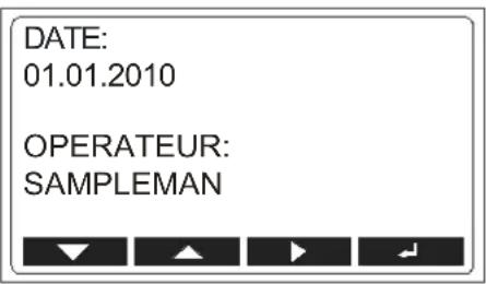
Figure 17: Affichage LCD menu "DATE/OPERATEUR"
MT204-S Machinery Tester
Manuale d'Uso
Amprobe Test Tools Europe
BEHA-AMPROBE GmbH
In den Engematten 14
79286 Glottertal
Germany
Tel.: +49 (0) 7684 8009 - 0
Fax: +49 (0) 7684 8009 - 410
www.amprobe.eu
info@amprobe.eu
ALTA TENSION, PERICOLO DIS COSSE ELETTRICE
MT204-S Machinery Tester
Manual de uso
Amprobe Test Tools Europe
BEHA-AMPROBE GmbH
In den Engematten 14
79286 Glottertal
Germany
Tel.: +49 (0) 7684 8009 - 0
Fax: +49 (0) 7684 8009 - 410
www.amprobe.eu
info@amprobe.eu
± (2% lect. + 2 digitos)
- Catalog
Application notes
Product specifications - User manuals
Beha-Amprobe
beha-amprobe.com
In den Engematten 14
79286 Glottertal, Germany
Tel.: +49 (0) 7684 8009 - 0

Please
Recycle