iOVEN P BX - Oven TEKA - Free user manual and instructions
Find the device manual for free iOVEN P BX TEKA in PDF.
User questions about iOVEN P BX TEKA
0 question about this device. Answer the ones you know or ask your own.
Ask a new question about this device
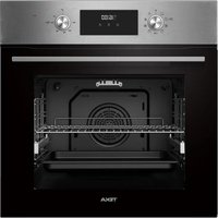
Download the instructions for your Oven in PDF format for free! Find your manual iOVEN P BX - TEKA and take your electronic device back in hand. On this page are published all the documents necessary for the use of your device. iOVEN P BX by TEKA.
USER MANUAL iOVEN P BX TEKA
natural_image
Modern kitchen interior with black cabinets and stainless steel appliances, featuring a 'TEKA' logo in the top right corner (no other text or symbols visible)Installation & Maintenance
ES PT EN
FR DE NL
EL
Installation and maintenance instructions index
SAFETY INSTRUCTIONS 29
Electrical safety 29
Child safety 30
Oven use safety 30
Safety in cleaning and maintenance 31
Safety when using the pyrolytic cleaning cycle .... 31
INSTALLATION 33
Before installation 33
Column installation 33
Undercounter installation 33
Electrical connection 33
Oven installation 33
ENVIRONmENTAL INFORmATION ...... 34
Disposal of the ecological packaging .. 34
Product disposal 34
Energy information 34
BEFORE FIRST USE 34
OTHER IMPORTANT INSTRUCTIONS .... 34
ACCESSORIES 35
Assembling the telescopic runners ..... 35 Telescopic runners with folding clip . 35 Telescopic runners with direct clip .. 35
CLEANING AND mAINTENANCE...... 36
Cleaning the oven exterior and accessories 36
Cleaning the oven interior .... 36 Assembling the side supports .... 36 Assembling the supports .... 36 Dismantling the bottom panel .... 36 Ovens with a folding grill .... 37
Cleaning the oven door .... 37 Dismantling/assembling the door with hinge on body .... 37 Dismantling/assembling the door with hinge on door .... 37 Dismantling/assembling the interior glass panes of the door .... 38
Changing the oven light bulb .... 38 Changing the upper bulb .... 38 Changing the side bulb .... 38 Changing the LED lamp .... 38
Trouble shooting .... 39 Technical Specifications .... 40
FIGURES 93
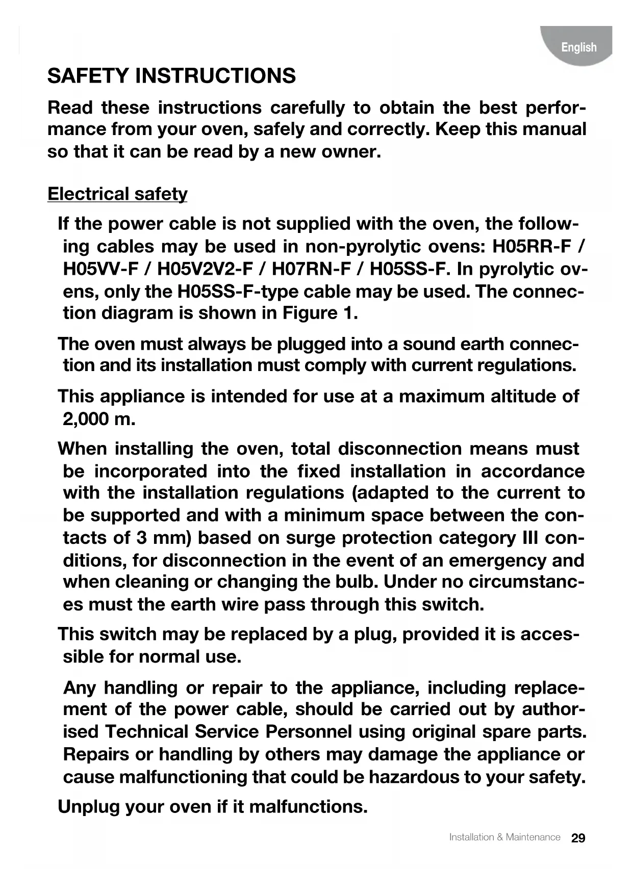
SAFETY INSTRUCTIONS
Read these instructions carefully to obtain the best performance from your oven, safely and correctly. Keep this manual so that it can be read by a new owner.
Electrical safety
If the power cable is not supplied with the oven, the following cables may be used in non-pyrolytic ovens: H05RR-F / H05VV-F / H05V2V2-F / H07RN-F / H05SS-F. In pyrolytic ovens, only the H05SS-F-type cable may be used. The connection diagram is shown in Figure 1.
The oven must always be plugged into a sound earth connection and its installation must comply with current regulations.
This appliance is intended for use at a maximum altitude of 2,000 m.
When installing the oven, total disconnection means must be incorporated into the fixed installation in accordance with the installation regulations (adapted to the current to be supported and with a minimum space between the contacts of 3 mm) based on surge protection category III conditions, for disconnection in the event of an emergency and when cleaning or changing the bulb. Under no circumstances must the earth wire pass through this switch.
This switch may be replaced by a plug, provided it is accessible for normal use.
Any handling or repair to the appliance, including replacement of the power cable, should be carried out by authorised Technical Service Personnel using original spare parts. Repairs or handling by others may damage the appliance or cause malfunctioning that could be hazardous to your safety.
Unplug your oven if it malfunctions.
In combined ovens with countertops and to avoid potential risks, only those recommended by the manufacturer may be assembled.
Child safety
Do not allow children to come near the oven while in use or during the pyrolytic cleaning cycle as it can reach very high temperatures.
Children under 8 years of age should be kept away from the appliance unless they are under constant supervision. Children should not be allowed to play with the appliance.
The appliance may be used by children over the age of 8 and people with reduced physical, sensory or mental capacities or a lack of experience or know-how, provided they have been given appropriate instructions or supervision on how to use the appliance safely and they understand the dangers involved.
Oven use safety
The oven must always be operated with the door closed.
Only use the oven after it has been installed inside the kitchen unit (See Installing the oven).
Do not install the oven behind decorative doors. This can cause it to overheat.
The manufacturer is not responsible for any use of the oven other than for the home preparation of food.
Do not cover the bottom of the oven with aluminium foil, or any other material, as this may affect cooking performance and damage the enamel inside the oven and the interior of your kitchen unit.
Do not store oil, fats or inflammable materials inside the oven. This may be dangerous if the oven is turned on.
Do not lean or sit on the open oven door. It could be damaged and you could be injured.
The tray and rack have a system for easy partial removal and handling of food. Always place these accessories inside the oven, as indicated in the Accessories section.
The oven heats up when in use, so always use oven gloves when performing operations inside the oven and avoid touching the heating elements.
Only use the supplied temperature probe inside the oven (in models that come with this feature).
Safety for cleaning and maintenance
Disconnect the appliance from the mains power supply before any operation.
Do not use steam cleaners or pressurised water to clean the oven.
Do not use metal scouring pads, wire brushes or commercially available or abrasive powder cleansers to clean the oven door as they can scratch the surface and cause the glass to break.
Cleaning and maintenance tasks to be carried out by the user should not be done by children without supervision.
Before replacing a bulb, first make sure that the oven has been disconnected from the mains to avoid the possibility of receiving an electric shock.
Remove all accessories and dishes from the oven, including the shelf supports and/or telescopic runners.
Clean any spillages or excess dirt, as during the pyrolytic cleaning cycle these could ignite and become a fire hazard.
For your safety, never operate the oven without the back panel (that protects the fan) in place.
Safety when using the pyrolytic cleaning cycle
Before starting the cleaning cycle:
CAUTION: Remove all accessories and dishes from the oven, including the shelf supports and/or telescopic runners.
Clean any spillages or excess dirt, as during the pyrolytic cleaning cycle these could ignite and become a fire hazard.
Remove any dirt from the oven gasket.
Carefully follow the instructions for programming the pyro- lytic cleaning cycle.
During the pyrolytic cleaning process:
Do not leave any cloths or fabric hanging from the oven handle or in close contact with it.
For safety reasons, if the oven has been installed below the counter, the hob must not be in use while the oven is in pyrolytic mode.
The oven's inside light will remain off and cannot be turned on. The oven is equipped with a safety lock mechanism that prevents the door from being opened during the cleaning cycle. Do not try to open the door while the lock is activated.

ORMATION
This manual describes general oven characteristics, and so they may not correspond in full to those of your oven. Consult the User's guide accompanying this manual to learn about the specific features and equipment of your oven.
The manufacturer reserves the right to change the product characteristics in order to improve its operation.
Installation
This information is exclusively for the installer who is responsible for assembly and electrical connection. The manufacturer will not accept liability for possible damage caused if you install the oven yourself.
bEFORE INSTALLATION
To handle the oven, use the grips at the sides. Do not use the door handle to lift the oven.
When installing the oven under a counter, follow the instructions for installing it.
In general, protruding elements (furniture reinforcements, pipes, socket bases, etc.) at the back of the unit must be avoided.
When the base of the main power socket is inside the unit in which the oven is installed, this must be done in the shaded area. Figure 2.
The unit in which the oven is installed and adjacent units must withstand temperatures higher than 85 °C.
The installation instructions must be adhered to strictly. If not, the oven's ventilation circuit may become blocked, causing high temperatures that could damage the kitchen unit and the appliance itself.
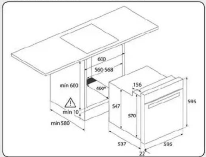
For this purpose, check the unit measurements and those of the holes to be drilled in the units, as shown in the following figures:
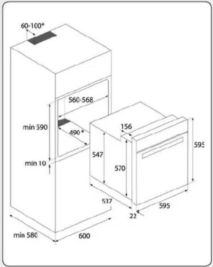
Column installation.
60 cm oven: Figure 7*.
45 cm oven: Figure 8*.

* When installing pyrolytic ovens, DO NOT drill any holes in the unit inside the shaded areas.
Undercounter installation.
60 cm oven: Figure 9*.
45 cm oven: Figure 10*.
* When installing pyrolytic ovens, DO NOT drill any holes in the unit inside the shaded areas.
ELECTRICAL CONNECTION
The fitter must ensure that:
The mains power voltage and frequency correspond to what is marked on the identification plate.
The domestic wiring system can withstand the maximum power marked on the identification plate.
After connecting the power supply, check that all electrical parts of the oven are working correctly.
OVEN INSTALLATION
For all ovens. After the electrical connection has been done:
-
Position the oven inside the unit and ensure that the feed cable is not trapped or in contact with parts of the oven that heat up.
-
Make sure that the body of the oven is not in contact with the walls of the unit and that there is a minimum space of 2 mm between adjacent units.
-
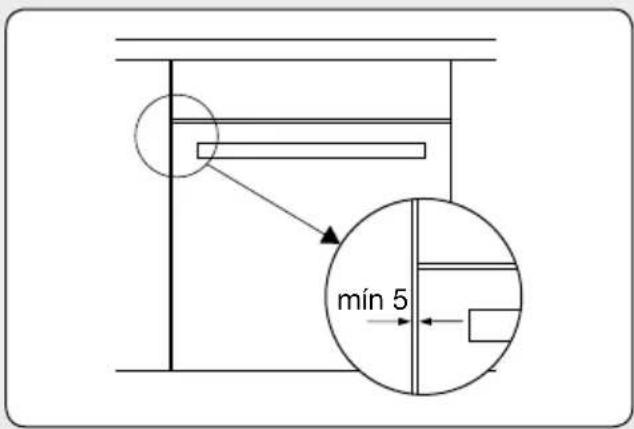
Centre the oven in the unit so that there is a minimum space of 5mm between the oven and the doors of the furniture that surrounds it. Figure 3.
-
Open the door and insert the plastic plugs supplied with the oven into their respective housings. Figure 11.
-
Fasten the oven to the unit with the screws supplied, screwing them into the unit through the stops.
Do not lean on the open door of the oven while executing steps 4 and 5, as the oven
is not secured to the unit and it could move forwards and fall to the floor.
Environmental information
DISPOSAL OF THE ECOLOGICAL PACK- AGING
The packaging is made from totally recyclable materials which can be put to other uses. Consult your local council regarding the necessary procedures for disposing of these materials.
PRODUCT DISPOSAL

NING
The symbol on the product or packaging indicates that this appliance cannot be disposed of as normal household waste. It should be taken to an electrical and electronic equipment collection point for recycling. In this way, any negative consequences for the environment and public health from incorrect handling can be avoided.
Contact your local council, household waste
disposal service or the establishment where you bought the product from for more information on recycling the appliance.
ENERGY INFORMATION
Tested to comply with the requirements of the 66/2014 (Eco-Design) and 65/2014 (Energy Labelling) regulations in accordance with Regulation EN 60350-1.
Energy consumption measurements taken under different conditions may give different values from those indicated for your oven.
Consult the User's guide accompanying this manual to learn about the energy consumption of your oven.
before first use
There may be traces of fat and other substances in the oven as a result of the manufacturing process. These should be removed using the following procedure:
- Remove all the packaging from your oven, including the protective plastic, if any.
-
Turn your oven to 📄 / 📋 or if this setting is not available to 🌱️ / 🌘 at 200 °C for 1 hour. Consult the User's guide accompanying this manual on how to do this.
-
Cool the oven with the door open so that it ventilates and no odours remain inside it.
- Once cold, clean the oven and the accessories.
During this first operation, smoke and smells will be produced. The kitchen should therefore be well ventilated.
Other important instructions
Do not pour water on the bottom surface when in use; this may damage the enamel.
It is normal for condensation to occur on the oven door when cooking food with a high liquid content.
When closing the oven door during cooking, the sound of the air inside it can be heard. This effect is normal due to the pressure exerted by the door when it is closed, guaranteeing the sealing of the cavity.
Accessories
Do not leave any containers or food on the oven floor. Always use the trays and racks supplied with the oven.
To prepare yoghurt, place the jars on the oven floor.
To cook any other food, insert the tray or rack into the runners inside the oven.
- Between the two rails of the side supports or on any of the extractable runners, if the oven has them.
- The rack and some of the trays have retention grooves to prevent them from accidentally being removed. Place these grooves towards the back of the oven, facing downwards. Figure 4.
- The surface of the rack on which the container will rest must be below the side rails. This prevents the container from accidentally sliding. Figure 5.
- The trays have a tab at the front to facilitate their removal. Place the tray with the tab facing towards the outside of the oven. Figure 6.
ASSEMBLING THE TELESCOPIC RUNNERS.
Some oven models have a telescopic runner kit accessory.
To assemble the telescopic runners on the chrome-plated supports, proceed as follows:
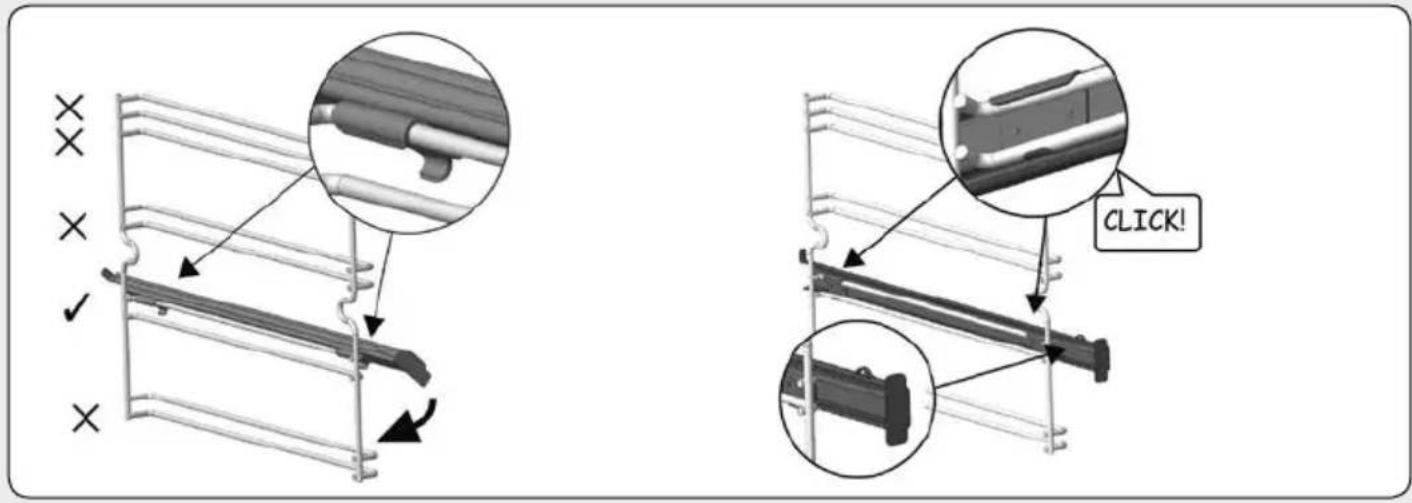
Telescopic runners with folding clip

WARNING
The runners must be placed at height 2, starting from below. Figure 12.
- Remove the protective film.
- Hook the large clips on the upper rail and extend the runner until it hooks on the small clips on the lower rail. Figure 12.
- You will hear a "click" when the runner is correctly secured. Figure 13.
- The notch to fix the tray/support must remain at the front part of the oven. Figure 13.
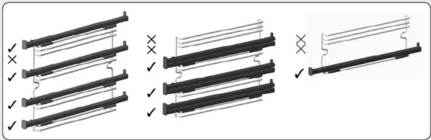
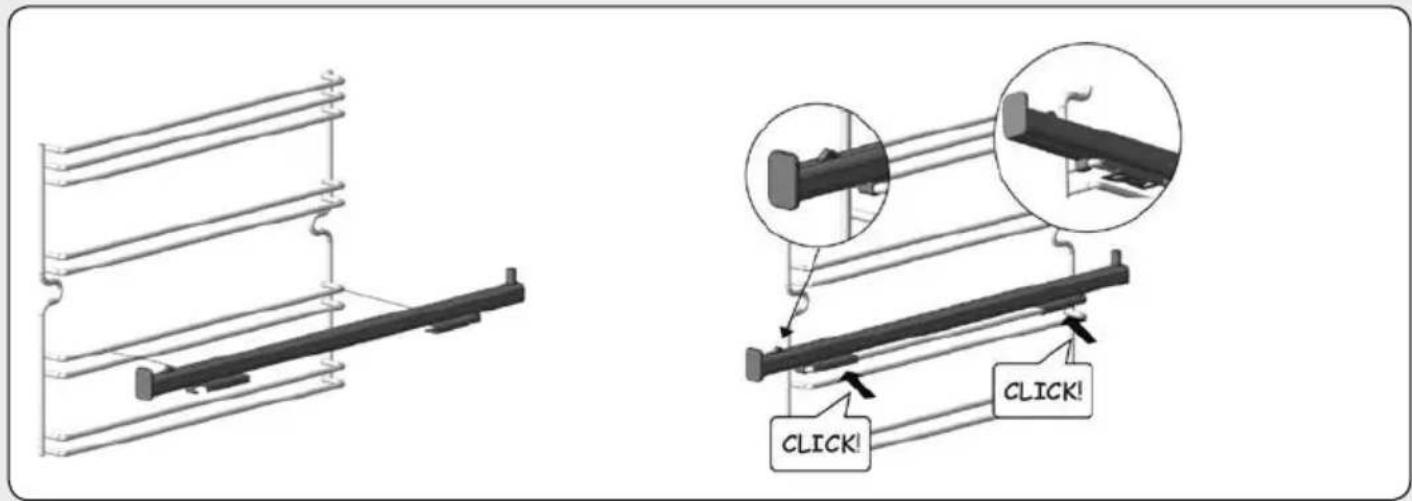
Telescopic runners with direct clip

WARNING
The single extraction runners must be placed at heights 1, 2, 3 and 5 starting from below. Figure 14.
The double extraction runners must be placed at heights 1, 2 and 3 starting from below. Figure 15.
In 45 cm ovens, the telescopic runners are positioned at height 1. Figure 16.
- Hook the clip on the top rail at the desired level. Figure 17.
- You will hear a "click" when the runner is correctly secured. Figure 18.
- The notch to fix the tray/rack support must remain at the front part of the oven. Figure 18.

WARNING
Disconnect the appliance from the mains power supply before any operation.
CLEANING THE OVEN ExTERIOR AND OVEN ACCESSORIES
Clean the outside of the oven and accessories with warm soapy water or with a mild detergent.
Take great care when cleaning stainless steel or painted surfaces. Use only sponges or cloths that do not scratch.

CAUTION
The telescopic runners must not be placed in the dishwasher. This will remove the fat that enables them to slide and the runners will become blocked, making them useless.
CLEANING THE OVEN INTERIOR
Clean the oven interior regularly to remove traces of fat or food, which can later give off smoke and odours and cause stains to appear.
Use nylon brushes or sponges with warm soapy water to clean enamelled surfaces such as the bottom of the oven. Clean when the oven is cold. Use oven-cleaning products only on enamelled surfaces and always follow the manufacturer's instructions.

WARNING
Do not clean the oven interior with steam or pressurised-water cleaning equipment.
Do not use metal scouring pads, wire brushes or any utensil that can scratch the enamel.
Over time, certain types of food such as toma-
toes, vinegar and salt-baked dishes may cause the enamel to change colour. This is normal and does not affect the functioning of the oven. Do not try to remove these stains using aggressive methods such as those described, as this could cause permanent damage to the surface.
Clean the oven seal regularly to eliminate all traces of fat or food. This will prevent the seal from becoming damaged and breaking during subsequent cooking operations.
It is advisable to clean this seal without removing it.
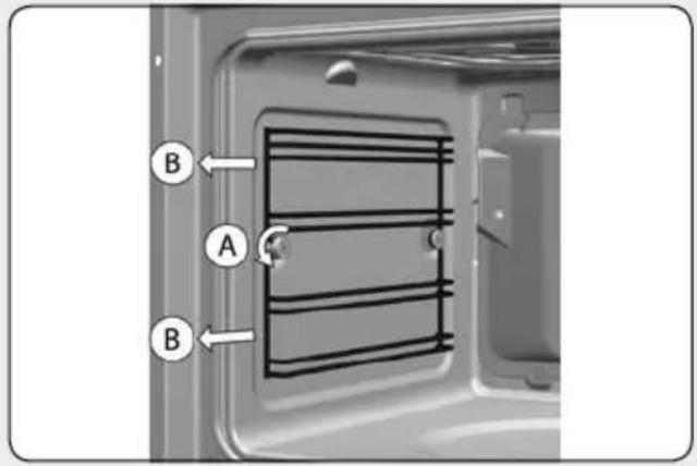
Dismantling the side supports
- Remove all accessories from inside the oven.
- Completely loosen the nut at the front of the fastening element (A), pull the supports forward (B) and remove them. Figure 19.
Assembling the supports
- Insert the rear notch into the rear fastening nut.
- Fix the front fastening nut (C) in the front notch of the support. Figure 20.
- Secure the support with the nut (D) and turn until it is fully adjusted (E). Figure 20.
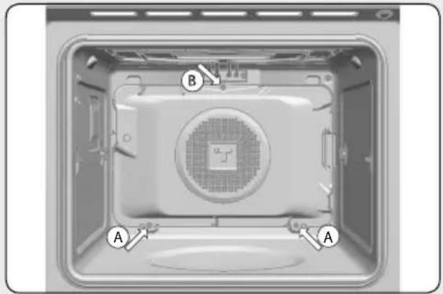
Dismantling the bottom panel

INFORMATION
To dismantle the bottom panel first dismantle the side supports, following the instructions set out in the previous section.
Then:
- Remove the bottom screws (A) and then the top screw (B). Figure 21.
- To assemble the bottom panel, proceed in the reverse order.

WARNING
For your safety, never operate the oven without the back panel (that protects the fan) in place.
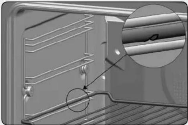
Ovens with a folding grill
To clean the top part of the oven:
- Wait until the oven is cold.
- Push the rail of the grill element (A) with both hands towards the back of the oven, to release it from the upper fastening nut (B). Figure 22.
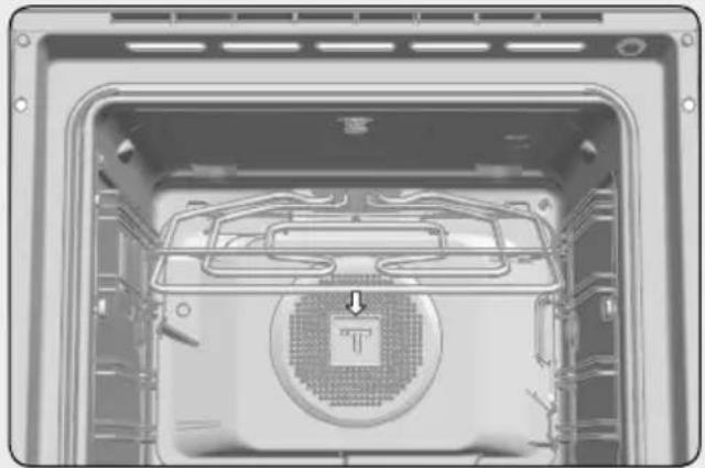
- Let the element fall and clean the top part of the oven. Figure 23.
- Then put the grill element back in place in its original position and proceed in the reverse order.
Ovens with the Teka Hydroclean® function
Please consult the oven User's guide.
Ovens with the Pyrolytic Self-Cleaning Function
Please consult the oven User's guide.
CLEANING THE OVEN DOOR
For easy cleaning, the door can be dismantled. To do this, follow the instructions for the type of door your oven has.
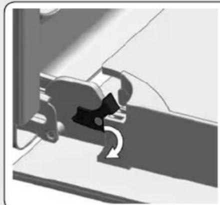
Dismantling/assembling the door with hinge on body
- Open the oven door fully.
-
Block the hinge by turning the latches. Figure 24.
-
Close the door to the locked position. Figure 25.
- Hold the door with both hands holding on to both sides, lift up and pull out the oven door until the hinges are fully detached Figure 25.
Assembling the door
-
Hold the door with both hands at the lower part of the sides, insert the hinge arms into their housings and let the door fall as far as it will go. Figure 26.
-
Open the oven door fully. Figure 26.
-
Turn the latches back to their original position.

WARNING
Make sure the door is inserted completely by turning the latches. If not, it can become blocked when trying to close it.

INFORMATION
If the latches are hard to turn, use a flat tool to turn them.
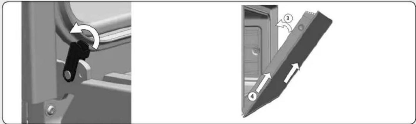
Dismantling/assembling the door with hinge on door
- Open the oven door fully.
- Block the hinge by turning both latches. Figure 27.
- Close the door to the locked position. Figure 28.
- Hold the door with both hands holding on to both sides, lift up and pull out the oven door until the hinges are fully detached. Figure 28.
To assemble the door, carry out the steps in the reverse order.
Dismantling/assembling the interior glass of the door

WARNING
If dismantling the glass panes with the door fitted in the oven, always do it with the hinge in the locked position. If not, the door will close and the unmounted glass panes could break and cause injury.

INFORMATION
To prevent this, dismantle the glass panes with the door removed, following the instructions in the previous section.
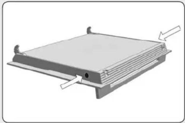
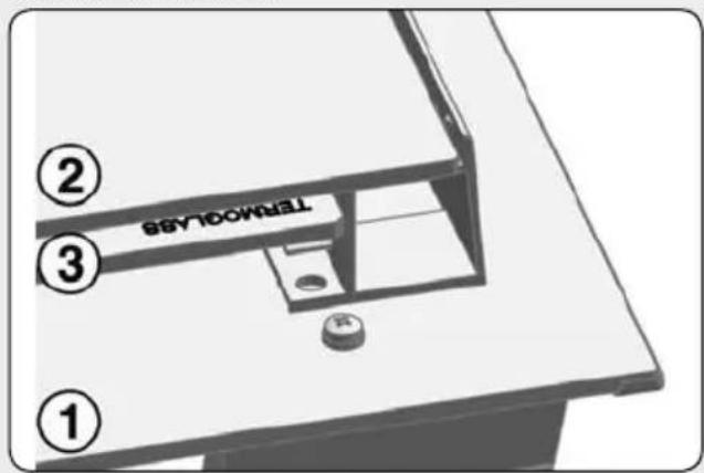
Depending on the model, your oven may have 2, 3 or 4 panes of glass. Follow the instructions for the type of door your oven has.
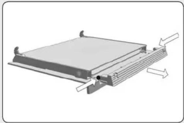
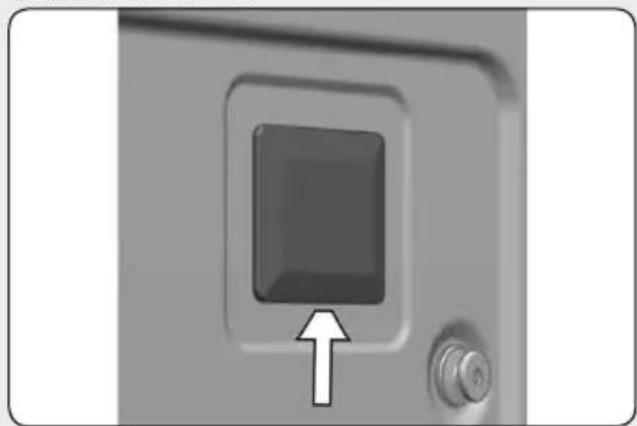
- Using your fingers, press the buttons located at the top of both sides of the oven door. Figure 29.
- Keep them pressed and pull on the plastic seal above the door. Figure 30.
- Remove the glass panes from the door. Clean them with a glass cleaner or soap and water and a soft cloth.

WARNING
Pay attention to the order and position of the glass panes when removing them as they must be reassembled in the same order and position when you have finished cleaning them.
- Once clean, insert pane no. 3 into the same position so that the TERMOGLASS indication printed on it is visible as shown in Figure 31.
-
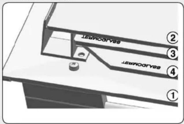
In pyrolytic ovens, the TERMOGLASS indication on panes numbers 3 and 4 must be visible as shown in Figure 32.
-
Insert pane no. 2 with the printed part facing toward the inner side of the door.
- Re-attach the top seal of the door, making sure that the side tabs fit into their housings.

WARNING
Never switch the oven on if any of the glass panes on the door are missing.
CHANGING THE OVEN LIGHT BULB

WARNING
Make sure the oven has been disconnected from the mains before changing the bulb.
The replacement bulb must withstand temperatures up to 300 °C. You can order them from the Technical Assistance Service Department.
Changing the upper bulb
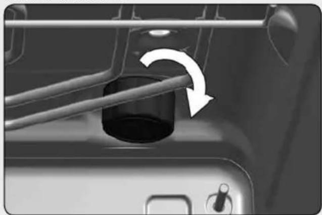
- Unscrew the glass cover of the bulb-holder. Figure 33.
- Replace the bulb and reassemble the glass cover.
Changing the side bulb
- Lift off the bulb-holder glass cover with a flat-ended tool. Figure 34.
- Change the bulb and reassemble the glass cover, ensuring that everything fits in the correct position.
Changing the LED lamp
Call the Technical Assistance Service Department.
Trouble shooting
This section describes some of the most frequent problems that can affect your oven,
along with the most common causes and possible solutions.
The oven stops working
Check the power connection.
Check the fuses and the circuit breaker of your installation.
Make sure the timer is either in the manual or programmed setting.
Check the position of the control and temperature dial.
The inside light does not go on
Change the bulb.
Check it has been properly installed as set out in the Installation Instructions.
The heating pilot light does not turn on
Select a temperature.
Select a setting.
It should only come on while the oven is heating up to the selected temperature.
Oven smoking during use
Normal during first use.
Clean the oven regularly.
Reduce the amount of fat or oil in the tray.
Do not cook at temperatures higher than those indicated in the cooking chart.
The expected cooking results are not achieved
Check the cooking charts for guidance on how your oven operates.
My accessories and shelf supports are damaged
You did not remove the accessories and supports during the pyrolytic cleaning cycle.
You must replace them and remove them during subsequent cleaning cycles.
The enamel colour has changed or stains have appeared
The chemical composition of some food-stuffs may cause changes in the enamel.
This is normal and does not damage the properties of the enamel.
The oven is off, the symbol lights up and the door will not open
The door lock is activated.
Deactivate the door lock following the instructions in the User's guide supplied with this manual.
The oven is on, the symbol lights up but the door will not open
The door lock is activated.
Turn the control dial to position ○.
Deactivate the door lock following the instructions in the User's guide supplied with this manual.
To continue cooking, re-select the desired cooking function.
I have turned the control dial to position and selected a pyrolysis programme (P1, P2 or P3) but the symbol flashes quickly and a buzzer sounds
The oven door is not closed properly, so the door cannot be locked and the pyrolytic process has been blocked.
Check the door and make sure it is properly closed. Then set the control dial to the ○ position and repeat the sequence to activate the pyrolysis.
I have turned the control dial to position 📄 and selected a pyrolysis programme (P1, P2 or P3) but the symbol 🔒 does not light up and the oven does not heat up
The door switch is not working even though the door is properly closed.
Call the Technical Assistance Service Department as there is a fault in the door switch.
The pyrolysis programme has ended and the oven is cold, but the door is locked and symbol ☐ and 0:00 are flashing
You did not turn the control dial to position - when the pyrolysis programme ended. Set the control dial to position - .
The control dial is in position and the door is still locked
The oven has not cooled down to the safe temperature limit.
Wait until the oven cools and the symbol goes off.
Technical specifications

WARNING
If these problems persist despite these tips, contact the Technical Service Department.
Inform the Technical Service Department of the kind of problem you are experiencing and give the:
- Serial Number (S-No)
- Model of Appliance (Mod.)
This information is on the oven identification plate which is on one side of the opened door.
INSTALLATION DU FOUR
REPLACEMENT DE L'AMPOULE DU FOUR

MISE EN GARDE
natural_image
Technical diagram of a rectangular structure with a central shaded section and a dimension label '90' (no text or symbols beyond the measurement)FIG. / AFB. / EIK. 4 FIG. / AFB. / EIK. 5
natural_image
Close-up of a refrigerator interior showing metal racks and a close-up inset of a coiled cable (no text or symbols visible)natural_image
Interior view of a microwave oven with a circular vent and a white arrow pointing to the interior (no text or symbols visible)FIG. / AFB. / EIK. 3
text_image
mín 5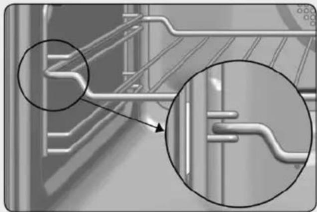
natural_image
Close-up of a mechanical pipe assembly with two magnified views highlighting internal components (no text or symbols)FIG. / AFB. / EIK. 7 FIG. / AFB. / EIK. 8
text_image
60-100* 560-568 490* min 590 min 10 547 156 570 537 22 595 595 min 580 600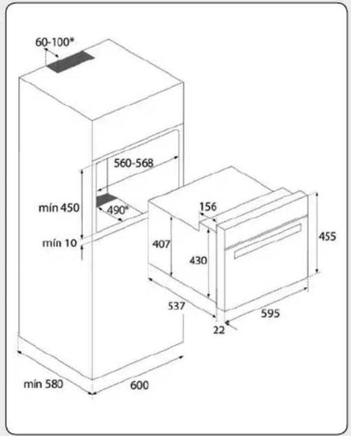
text_image
60-100* 560-568 490* min 450 min 10 407 156 430 537 22 595 455 min 580 600FIG. / AFB. / EIK. 9 FIG. / AFB. / EIK. 10
text_image
600 560-568 490° min 600 min 10 min 580 156 547 570 537 22 595 595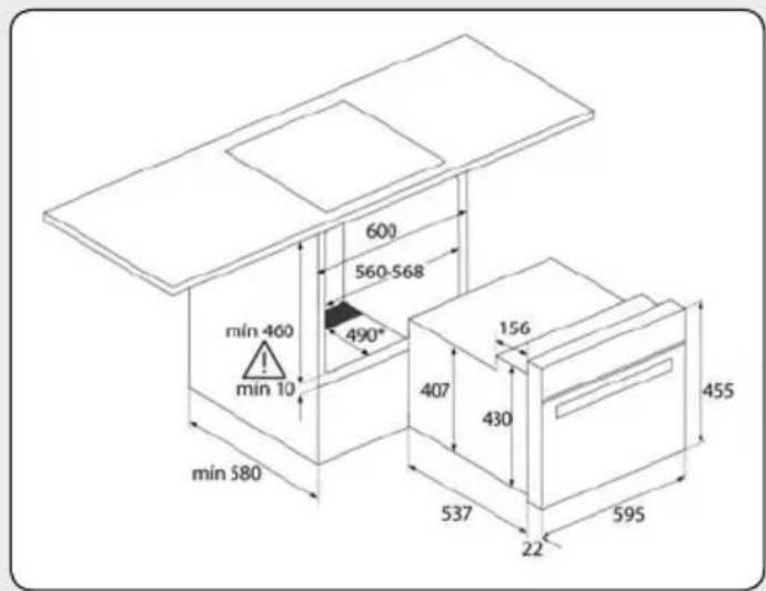
text_image
600 560-568 490° min 460 min 10 min 580 156 407 430 537 22 595 455FIG. / AFB. / EIK. 11
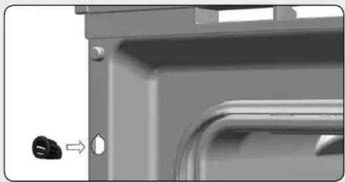
natural_image
Close-up of a mechanical component with a black connector and a white circular detail, no visible text or symbols* Para hornos pirolíticos NO realizar las aperturas.
* Para fornos pirolíticos, NÃO faça as aberturas.
* For pyrolytic ovens, DO NOT drill any holes.
* NE PAS réaliser d'ouverture pour des fours pyrolytiques.
* Für die Pyrolyseöfen NICHT die Öffnungen sägen.
* Voor pyrolytische ovens GEEN gaten maken.
* MHN κάνετε τα ανοίγματα όταν πρόκειται για πυρολυτικούς φούρνους.
FIG. / AFB. / EIK. 12 FIG. / AFB. / EIK. 13
text_image
Technical diagram illustrating mechanical assembly steps with magnified views and instruction labelsFIG. / AFB. / EIK. 14
FIG. / AFB. / EIK. 15
FIG. / AFB. / EIK. 16
text_image
Technical diagram showing three stages of a mechanical assembly with checkmarks indicating status or modification.FIG. / AFB. / EIK. 17 FIG. / AFB. / EIK. 18
text_image
Technical diagram showing two mechanical assembly configurations with labeled click points and a magnified detail of the main component.FIG. / AFB. / EIK. 19 FIG. / AFB. / EIK. 20
text_image
B A B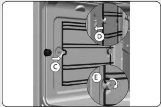
text_image
Diagram of a refrigerator interior with labeled parts C, D, and E showing internal wiring or componentsFIG. / AFB. / EIK. 21 FIG. / AFB. / EIK. 22
text_image
Diagram of a microwave oven interior with labeled components A and B, showing internal air vent and fan structure.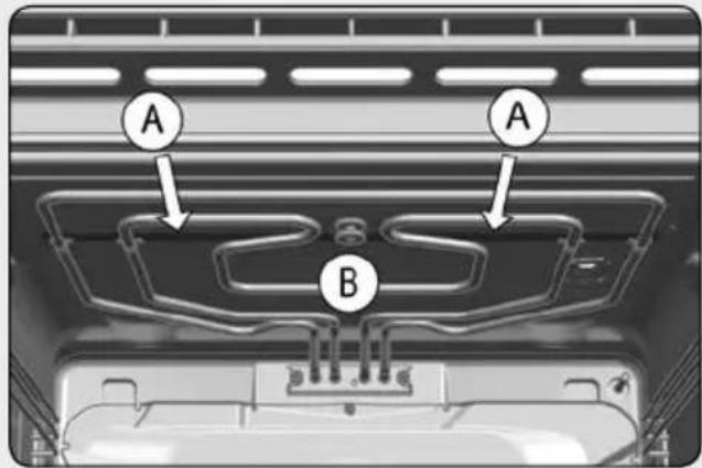
text_image
A A BFIG. / AFB. / EIK. 23
natural_image
Interior view of a computer oven with visible circuitry and a central mesh pattern (no text or symbols)FIG. / AFB. / EIK. 25
FIG. / AFB. / EIK. 26
FIG. / AFB. / EIK. 24
natural_image
Mechanical component diagram showing a lever mechanism with a curved arrow indicating rotation (no text or symbols present)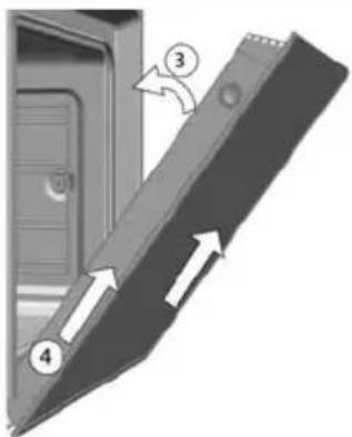
text_image
Diagram showing a mechanical component with numbered parts and directional arrows indicating motion or force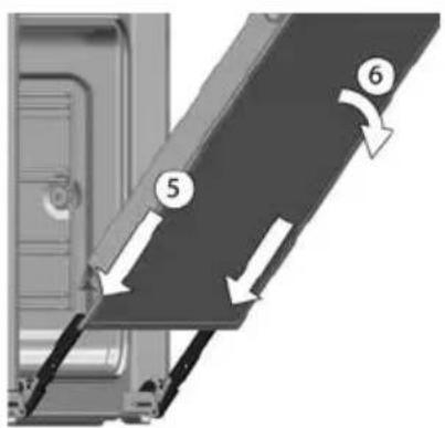
text_image
Diagram showing a mechanical or structural component with numbered parts and directional arrows indicating motion or flow.FIG. / AFB. / EIK. 27 FIG. / AFB. / EIK. 28
natural_image
Mechanical assembly diagram showing a lever mechanism and a 3D panel with directional arrows (no text or symbols)FIG. / AFB. / EIK. 29
natural_image
3D diagram of a rectangular electronic component with mounting feet and internal structure, showing no text or symbols.FIG. / AFB. / EIK. 31
text_image
TERMOULSS ① ② ③FIG. / AFB. / EIK. 33
natural_image
Close-up of a car interior showing a cylindrical component being inserted by a tool, with an arrow indicating rotation (no text or symbols present)FIG. / AFB. / EIK. 30
natural_image
Diagram of a layered electronic component with directional arrows indicating flow or movement (no text or symbols)FIG. / AFB. / EIK. 32
text_image
sealgoon sealgoon sealgoon ① ② ③ ④FIG. / AFB. / EIK. 34
natural_image
Close-up of a black square button with an arrow pointing to it, mounted on a door panel (no text or symbols visible)Teka Subsidiaries
| Country Subsidiary | Address | City | Phone |
| AustriaKüppersbusch Austria | Eitnergasse, 13 | 1231 Wien | +43 18 668 022 |
| BelgiumKüppersbusch Belgium S.P.R.L. | Doomveld Industrie, Asse 3, No. 11 - Boite 7 | 1731 Zellik | +32 24 668 740 |
| BulgariaTeka Bulgaria EOOD | Blvd. "Tsarigradsko Shosse" 135 | 1784 Sofia | +359 29 768 330 |
| ChileTeka Chile S.A. | Avd El Retiro Parque los Maitenes, 1237. Parque Enea | Pudahuel, Santiago de Chile | +56 24 386 000 |
| ChinaTeka International Trading (Shanghai) Co. Ltd. | No.1506, Shengyuan Henghua Bldg. No.200 Wending Rd. | Xuhui, Dist. 200030 Shanghai | +86 2 153 076 996 |
| Czech RepublicTeka CZ S.R.O. | V Holesovickách, 593 | 182 00 Praha 8 - Liben | +420 284 691 940 |
| EcuadorTeka Ecuador S.A. | Parque Ind. California 2, Via a Daule Km 12 | Guayaquil | +593 42 100 311 |
| GreeceTeka Hellas A.E. | Thesi Roupaki - Aspropyrgos | 193 00 Athens | +30 2 109 760 283 |
| HungaryTeka Magyarország Zrt. | Terv u. 92 | 9200 Mosonmagyaróvár | +36 96 574 500 |
| IndonesiaPT Teka Buana | Jalan Menteng Raya, Kantor Taman A9 Unit A3 | 12950 Jakarta | +62 215 762 272 |
| MalaysiaTeka Küchentechnik (Malaysia) Sdn Bhd | 10 Jalan Kartunis U1/47, Temasya Park, Off Glenmarie | 40150 Shah Alam, Selangor Darul Ehsan | +60 376 201 600 |
| MexicoTeka Mexicana S.A. de C.V. | Blvd Manuel A. Camacho 126, Piso 3 Col. Chapultepec | 11000 Mexico D.F. | +52 5 551 330 493 |
| MoroccoTeka Maroc S.A. | 73, Bd. Slimane, Depôt 33, Route de Ain Sebaa | Casablanca | +212 22 674 462 |
| PeruTeka Küchentechnik Perú S.A. | Av. El Polo 670 local A 201, CC El polo, Surco | Lima | +51 14 363 078 |
| PolandTeka Polska Sp. ZO.O. | ul. 3-go Maja 8 / A2 | 05-800 Pruszkow | +48 227 383 270 |
| PortugalTeka Portugal S.A. | Estrada da Mota - Apdo 533 | 3834-909 Ilhavo, Aveiro | +35 1 234 329 500 |
| RomaniaS.C. Teka Küchentechnik Romania S.R.L. | Sevastopol str., no 24, 5th floor, of. 15 | 010992 Bucharest Sector 1 | +40 212 334 450 |
| Russia/PоссияTeka Rus LLC/000 "Teka Pyc" | Neverovskogo 9, Office 417, 121170, Moscow, Russia | 121087 Россия, Москва | +7 4 956 450 064 |
| SingaporeTeka Singapore PTE Ltd | Clemenceau Avenue, 83, 01-33/34 UE Square | 239920 Singapore | +65 67 342 415 |
| SpainTeka Industrial, S.A. | C/ Cajo,17 | 39011 Santander | +34 942 355 050 |
| ThailandTeka (Thailand) Co. Ltd. | 364/8 Sri-Ayuttaya Road, Phayathai, Ratchatavee | 10400 Bangkok | +66-26 424 888 |
| TurkeyTeka Teknik Mutfak Aletleri Sanayi Ve | Büyükdere Cad. 24/13 | 80290 Mecidiyeköy, Istanbul | +90 2 122 883 134 |
| UkraineTeka Ukranie LLC | 86-e, Bozhenko Str -2nd floor,4th entrance | 03150 Kyiv | +380 444 960 680 |
| United Arab EmiratesTeka Middle East Fze | Building LOB 16, Office 417 | P.O. Box 18251 Dubai | +971 48 872 912 |
| United Arab EmiratesTeka Küchentechnik U,A,E LLC | Bin Khedia Centre | P.O. Box 35142 Dubai | +971 42 833 047 |
| VenezuelaTeka Andina S.A. | Ctra. Petare-Santa Lucia, km 3 (El Limoncito) | 1070 Caracas | +58 2 122 912 821 |
| VietnamTEKA Vietnam Co., Ltd. | 803, FI 8th, Daiminh Convention Center, 77, Hoang Van | Thai, Tan Phu Ward, District 7, Ho Chi Minh | +84 854 160 646 |

text_image
TEKA