
AMB50 - Measuring equipment Amprobe - Free user manual and instructions
Find the device manual for free AMB50 Amprobe in PDF.
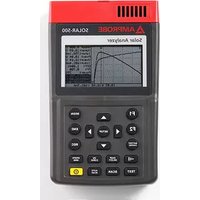
| Product type | 5000 V insulation resistance tester |
| Brand and model | Amprobe AMB50 |
| Test voltage ranges | 500 V, 1000 V, 2500 V, 5000 V |
| Resistance measurement ranges | 0.5 MΩ to 20 GΩ (500 V), 2 MΩ to 40 GΩ (1000 V), 5 MΩ to 100 GΩ (2500 V), 100 MΩ to 1000 GΩ (5000 V) |
| Voltage measurement | 30-600 V DC and AC (50/60 Hz) |
| Display | Digital LCD 9999 counts, analog bar graph |
| Power supply | 8 LR14 (1.5 V) batteries or 14 V DC, 1.0 A mains adapter |
| Dimensions (H x W x D) | 202 x 155 x 94 mm |
| Weight | Approximately 2 kg (with batteries) |
| Safety category | CAT III 600 V, double insulation, pollution degree 2 |
| PC interface | USB with included software |
| Data memory | 18 locations |
| Special functions | Continuous, timed measurement, polarization index (PI), pass/fail comparison |
| Included accessories | Test leads (red 2 plugs, black 1 plug, green 1 plug), carrying case, software, USB cable, mains adapter |
| Battery life | Sleep mode after 15 minutes of inactivity |
| Operating temperature | 0 °C to 40 °C |
| Operating humidity | ≤ 85 % RH |
| Cleaning and maintenance | Soft cloth and mild detergent; do not use solvents |
| Spare parts and repairability | LR14 batteries, mains adapter, test leads; repair at authorized center |
Frequently Asked Questions - AMB50 Amprobe
User questions about AMB50 Amprobe
0 question about this device. Answer the ones you know or ask your own.
Ask a new question about this device
Download the instructions for your Measuring equipment in PDF format for free! Find your manual AMB50 - Amprobe and take your electronic device back in hand. On this page are published all the documents necessary for the use of your device. AMB50 by Amprobe.
USER MANUAL AMB50 Amprobe
5000V Insulation Resistance Tester
Users Manual
- Mode d'emploi
• Bedienungshandbuch - Manual d'Uso
- Manual de uso
AMPROBE®
AMB-50
5000V Insulation Resistance Tester
Users Manual
Limited Warranty and Limitation of Liability
Your Amprobe product will be free from defects in material and workmanship for 1 year from the date of purchase. This warranty does not cover fuses, disposable batteries or damage from accident, neglect, misuse, alteration, contamination, or abnormal conditions of operation or handling. Resellers are not authorized to extend any other warranty on Amprobe's behalf. To obtain service during the warranty period, return the product with proof of purchase to an authorized Amprobe Test Tools Service Center or to an Amprobe dealer or distributor. See Repair Section for details. THIS WARRANTY IS YOUR ONLY REMEDY. ALL OTHER WARRANTIES - WHETHER EXPRESS, IMPLIED OR STAUTORY - INCLUDING IMPLIED WARRANTIES OF FITNESS FOR A PARTICULAR PURPOSE OR MERCHANTABILITY, ARE HEREBY DISCLAIMED. MANUFACTURER SHALL NOT BE LIABLE FOR ANY SPECIAL, INDIRECT, INCIDENTAL OR CONSEQUENTIAL DAMAGES OR LOSSES, ARISING FROM ANY CAUSE OR THEORY. Since some states or countries do not allow the exclusion or limitation of an implied warranty or of incidental or consequential damages, this limitation of liability may not apply to you.
Repair
All test tools returned for warranty or non-warranty repair or for calibration should be accompanied by the following: your name, company's name, address, telephone number, and proof of purchase. Additionally, please include a brief description of the problem or the service requested and include the test leads with the meter. Non-warranty repair or replacement charges should be remitted in the form of a check, a money order credit card with expiration date, or a purchase order made payable to Amprobe® Test Tools.
In-Warranty Repairs and Replacement – All Countries
Please read the warranty statement and check your battery before requesting repair. During the warranty period any defective test tool can be returned to your Amprobe® Test Tools distributor for an exchange for the same or like product. Please check the "Where to Buy" section on www.amprobe.com for a list of distributors near you. Additionally, in the United States and Canada In-Warranty repair and replacement units can also be sent to a Amprobe® Test Tools Service Center (see address below).
Non-Warranty Repairs and Replacement – US and Canada
Non-warranty repairs in the United States and Canada should be sent to a Amprobe® Test Tools Service Center. Call Amprobe® Test Tools or inquire at your point of purchase for current repair and replacement rates.
In USA In Canada
Amprobe Test Tools Amprobe Test Tools
Everett, WA 98203 Mississauga, ON L4Z 1X9
Tel: 877-AMPROBE (267-7623) Tel: 905-890-7600
Non-Warranty Repairs and Replacement – Europe
European non-warranty units can be replaced by your Amprobe® Test Tools distributor for a nominal charge. Please check the "Where to Buy" section on www.amprobe.com for a list of distributors near you.
European Correspondence Address*
Amprobe® Test Tools Europe
In den Engematten 14
79286 Glottertal, Germany
Tel.: +49 (0) 7684 8009 - 0
*(Correspondence only – no repair or replacement available from this address. European customers please contact your distributor.)
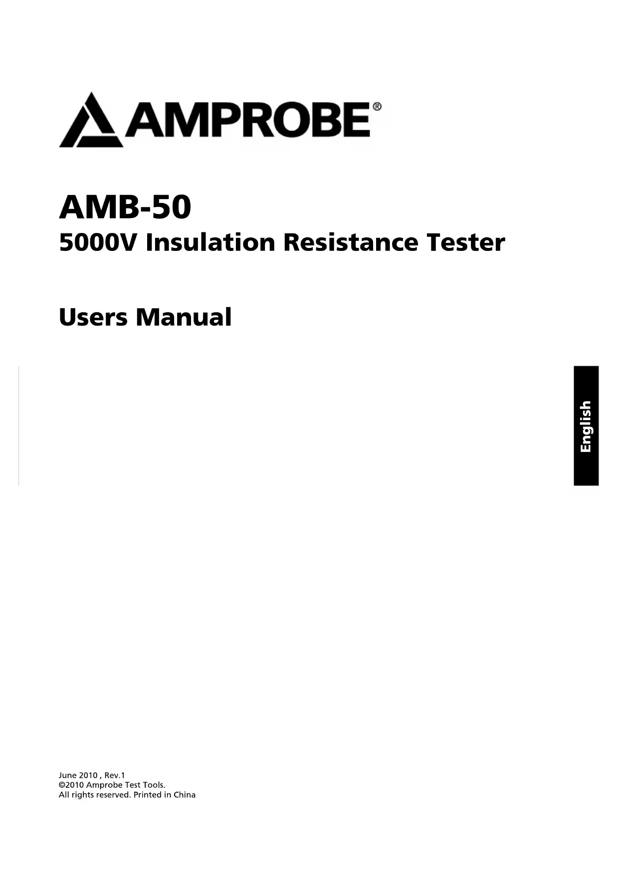
1 LCD
2 Scroll Button
3 Emergency Stop
4 Data Clear the Display Backlight Button
5▼ Down Button
6 On/Off Button
7 Compare Button
8 Insulation Resistance Button
9 DC Voltages measurement Button
10 Timer Button.
11 AC Voltages measurement Button
12 Test Button
13 USB Button
14 Data Store Button.
15 Data Recall Button
16▶ Scroll Button
17 ▲ Up Button
18 LINE: High Voltage output input terminal (two plugs red test lead to one alligator clip)
19 High voltage line shielding input terminal (two plugs red test lead to one alligator clip)
20 GUARD: Grounding protection input terminal (one plug black test lead to one alligator clip)
21 EARTH: High resistance measurement input terminal (one plug green test lead to one alligator clip)
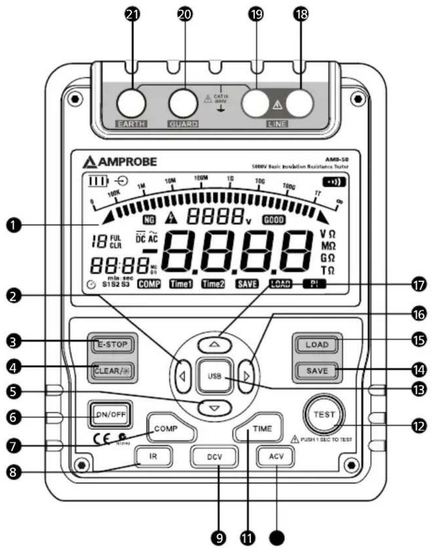
● Testing leads:
Two plugs red test lead to one alligator clip. One plug black test lead to one alligator clip. One plug green test lead to one alligator clip.
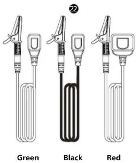
1 Safety Shutter
② Power adaptor Input Terminal
3 USB Port
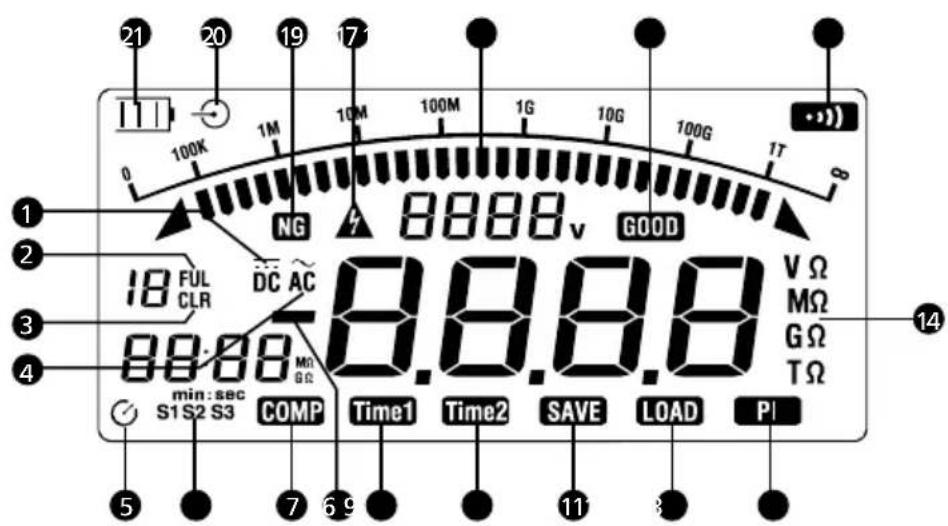
1 Indicator for DC voltage
② Indicator for data store full
3 Indicator for clearing
4 Indicator for AC voltage
⑤ Indicator for timer
6 Step symbol
7 Indicates selected pass/fail compare value
8 Indicates for negative reading
9 Timer 1 symbol
10 Timer 2 symbol
11 Data store is on
12 Data recall is on
13 Indicator for polarization index
14 Unit symbols
15 The continuity buzzer is on
16 Compare result pass
17 Analogue bar graph
18 Risk of electric shock
19 Compare result fail
20 Indicator for power adaptor
21 Battery life indicator
CONTENTS
SYMBOLS AND WARNINGS....2
Symbols 2
UNPACKING AND INSPECTION 2
INTRODUCTION 2
SAFETY INFORMATION ....3
OPERATION....4
Key Functions....4
A.Measuring Voltages 5
B.Measuring Insulation Resistance....6
Information....7
The Use of Power Adaptor....8
USB Interface 8
Battery Saver (Sleep Mode)....9
Battery Indication....9
SPECIFICATIONS....9
PHYSICAL SPECIFICATIONS....9
General Specifications....9
Feature Summary....10
Detailed Accuracy Specifications....10
MAINTENANCE AND REPAIR ....11
Replacing the Battery....12
SOFTWARE INSTALLATION GUIDE & OPERATING....13
Software Installation....13
User's Guide 15
SYMBOLS
 | Battery |  | Refer to the manual |
| [338V] | Double Insulated | [067D] | Dangerous Voltage |
| [5712H] | Alternating Current | [HZWH] | Earth Ground |
| [8V23] | Direct Current | [AX7D] | Thermal fuse rated 130°C |
| [K758] | Application around and removal from hazardous live conductors is permitted |  | Complies with EU directives |
| [KX88] | Do not dispose of this product as unsorted municipal waste | [96WD] | Conform to relevant Australian standards |
UNPACKING AND INSPECTION
Your shipping carton should include:
1 AMB-50 Insulation Resistance Tester
1 Complete set of Test Leads
- 1 Plug type test Lead with Alligator clip (Green)
- 1 Plug type test Lead with Alligator clip (Black)
- 1 Two Plugs type test lead with Alligator clip (Red)
8 Batteries (1.5V, LR14)
1 Users Manual
1 Tool Box
1 Software
1 USB Cable
1 Power adaptor
If any of the items are damaged or missing, return the complete package to the place of purchase for an exchange.
INTRODUCTION
AMPROBE, AMB-50 insulation resistance tester is a handheld instrument designed primarily to make resistance/ insulation resistance measurement.
SAFETY INFORMATION
This Meter complies with the standards IEC61010 safety measurement requirement: in pollution degree 2, overvoltage category (CAT. III 600V) and double insulation.
CAT II: Local level, appliance, PORTABLE EQUIPMENT etc., with smaller transient voltage overvoltages than CAT. III
Use the Meter only as specified in this operating manual, otherwise the protection provided by the Meter may be impaired.
⚠️DANGER! - identifies conditions and actions that pose hazard(s) to the user
⚠ WARNING! - identifies avoiding electric shock.
⚠️ CAUTION! - identifies conditions and actions that may damage the Meter and carrying out accurate measurement.
⚠️DANGER!
Use of instrument in a manual not specified by the manufacturer may impair safety features/protection provided by the equipment. Read the following safety information carefully before using or servicing the instrument.
- Do not apply more than 600V.
- Do not use the Meter around explosive gas, vapor or dust.
- Do not use the Meter in a wet environment.
- When using the test leads, keep your figures away from the lead contacts. Keep your figures behind the finger guards on the leads.
- Do not use the Meter with any parts or cover removed.
- When carrying out insulation measurement, do not contact the circuit under test.
⚠ WARNING!
- Do not use the Meter if it is damaged or metal part is exposed. Look for cracks or missing plastic.
- Be careful when working above 33V rms, 46.7V ac rms or 70V DC. Such voltages pose a shock hazard.
- Discharge all loading of circuit under test after measuring high voltage.
- Do not change battery when the Meter is in wet environment.
- Place test leads in proper input terminals. Make sure all the test leads are firmly connected to the Meter's input terminals.
- Make sure the Meter is turned off when opening the battery compartment.
- Do not use the power adaptor and the USB cable during insulation testing. Use for data downloading only.
⚠️ CAUTION!
- When performing resistance tests, remove all power from the circuit to be measured and discharge all the power.
- When servicing the Meter, use only the same model number or identical electrical specifications of test leads and power adaptor.
- Do not use the Meter if the battery indicator (⊃) shows a battery empty condition. Take the battery out from the Meter if it is not used for a long time.
- Do not use or store the Meter in an environment of high temperature, humidity, explosive, inflammable and strong magnetic field. The performance of the Meter may deteriorate after dampened.
- Soft cloth and mild detergent should be used to clean the surface of the Meter when servicing. No abrasive and solvent should be used to prevent the surface of the Meter from corrosion, damage and accident.
- Dry the Meter before storing if it is wet.
Key Functions
| ON/OFF | Turn on or off the Meter. Press and hold the button for 1 second to turn the Meter on. Press again to turn off the Meter.The Meter default range is 500V insulation resistance continuous measurement when turning on. |
| E-STOP | Emergency stop button. Press this button when the Meter's operating system crashed and can not stop measurement. |
| CLEAR / ★ | Press to turn on or off the display backlightPress and hold to clear the stored data |
| SAVE | Press to store the current measurement value. The maximum number of stored reading is 18. When the stored readings memory is full, the Meter shows FULL and stop storing. Press and hold CLEAR / ★ to clear the stored value in order to store the next measurement |
| value. | |
| LOAD | Press once to recall the first stored value.Press again to exit Load feature.Load feature can only be used when there is no high voltage output. |
| ▲ | When the insulation resistance measurement has no testing voltage output, press to select one voltage range up.Under load mode: press to recall the previous stored value. |
| ▼ | When the insulation resistance measurement has no testing voltage output, press to select one voltage range down.Under load mode: press to recall the next stored value. |
| ◀ | When set the timer duration for the measurement of insulation resistance or polarization index, press to decrease the time. The maximum length of time is 15 minutes, the Meter will automatically carry out measurement.When compare feature measuring insulation resistance, press to decrease a resistance comparing value.After polarization index measurement, press to display polarization index, TIME 2 insulation resistance value and TIME 1 insulation resistance value in sequence. |
| ▶ | When set the timer duration for the measurement of insulation resistance or polarization index, press to increment the time. The maximum length of time is 15 minutes, the Meter will automatically carry out measurement.When use the compare feature measuring insulation resistance, press to increase a resistance comparing value.After polarization index measurement, press to display polarization index, TIME 2 insulation resistance value and TIME 1 insulation resistance value in sequence. |
| USB | Press once to start the data transferring to the computer via USB, USB symbol shows on the display.Press again to stop the data transferring to the computer via USB, USB symbol disappears. |
| COMP Set a pass / fail limit for insulation tests. The default value is 10M Ohm | |
| TIME | Pres to step through continuous measurement, timed measurement and polarization index measurement in sequence. |
| TEST Press to stop or start an insulation resistance test | |
| IR Press to initiate insulation resistance measurement | |
| DCV Press to initiate DC voltage measurement | |
| ACV Pres to initiate AC voltage measurement | |
Below section explains how to make measurements.
Press and hold ON/OFF to turn on the Meter, press again to turn off the Meter. The Meter default range is 500V insulation resistance continuous measurement when turning on.
A. Measuring Voltages
OPERATING CAUTION!
- To avoid harms to you or damages to the Meter, please do not attempt to measure voltages higher than 600V or 600V rms, although readings may be obtained.
- Special care should be taken when measuring high voltage.
To measure voltages, set up the Meter as above and do the following:
- Press DCV or ACV button to select DC voltage or AC voltage measurement
- Insert the red and green test lead into the tested circuit.
- When measuring DC voltage, if the red test lead is negative voltage, - symbol will show on the display.
Note
- When voltage measurement has been completed, disconnect the connection between the testing leads and the circuit under test and remove testing leads away from the input terminals of the Meter.
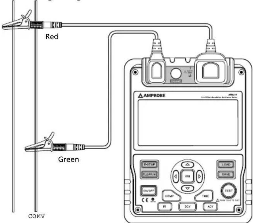
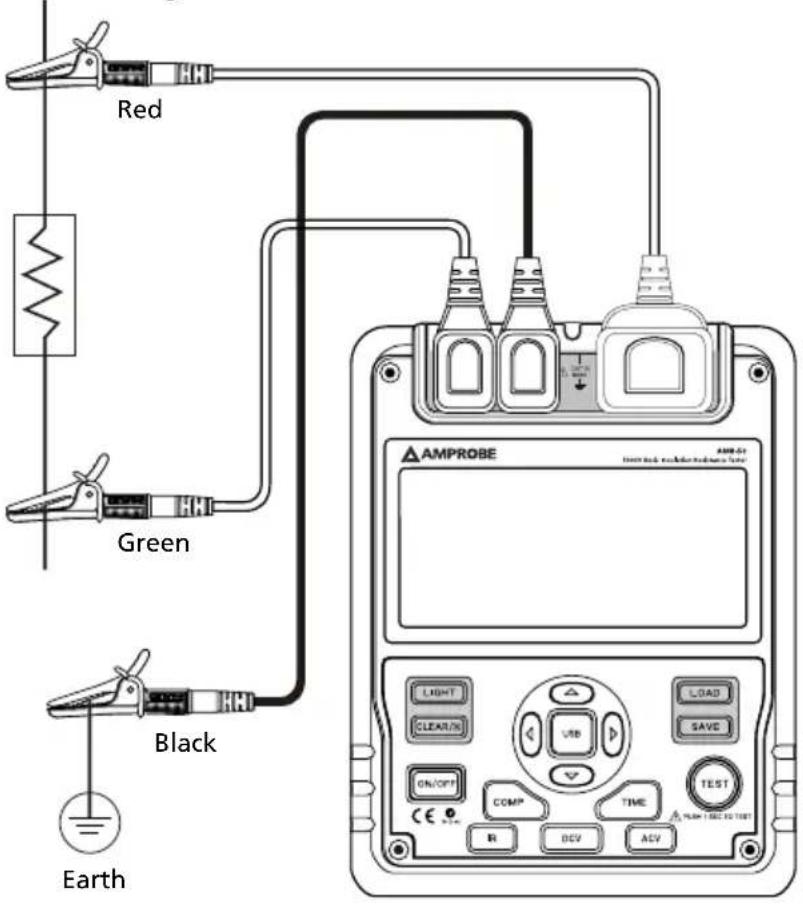
B. Measuring Insulation Resistance
OPERATING CAUTION!
- When performing insulation resistance tests, remove all power from the circuit to be measured and discharge all the power.
- Operating the Meter must be very careful as it outputs dangerous voltage during measurement. Must make sure the tested object is firmed clipped, hands are away from the clips, then press TEST button to put high voltage.
- Do not short circuit the testing leads during high voltages output or test insulation resistance after high voltages output. This kind of incorrect operating may cause sparking and fire, which damages the Meter and harms to you.
- Do not measure over 10 seconds when: 500V measure resistance lower than 2MΩ 1000V measure resistance lower than 5MΩ 2500V measure resistance lower than 10MΩ 5000V measure resistance lower than 20MΩ
To measure insulation resistance, set up the Meter as above and do the following:
- Press IR button to select insulation resistance measurement.
- When there is no testing voltage output, press ▲ and ▼ button to select voltages of 500V, 1000V, 2500V or 5000V.
- When performing insulation resistance tests, remove all power from the circuit to be measured and discharged all the power.
-
Insert the red test lead into the LINE input terminal and the black test lead into GUARD input terminal.
-
Connect the red and black alligator clip to the circuit to be measured, negative voltage output from LINE terminal.
-
Choose below insulation resistance measurement mode.
a) Continuous Measurement
- Press TIME button to select continuous measurement mode, there is no timer icon on the LCD.
- Press ◀ and ▶ hold TEST button for 1 second to start continuous measurement. Output insulation resistance testing voltage, TEST button light up, △ blinks on every 0.5 seconds.
- Press TEST button to stop the insulation resistance measurement. TEST button lights off, △ disappears. The LCD shows the current insulation resistance measurement value.
b) Timed Measurement
- Press TIME button to select timed measurement mode, the LCD displays TIME 1 and symbols.
- Press and buttons to set the time (00:05\~15:00). Within 1 minute, the time increase or decrease by every 5 seconds. Afterward, the time increase or decrease by every 30 seconds.
- Then press and hold TEST button for 2 second to start timed measurement. TIME 1 and are displayed and blinked on the LCD on every 0.5 seconds.
- When the set time is reached, the insulation resistance measurement voltage will be closed and the measurement will be automatically stopped. The LCD displays the insulation resistance reading.
c) Polarization Index (PI) Measurement
- Press TIME button to select timed measurement mode, the LCD displays TIME 1 and symbols.
- Press and buttons to set the time (00:05\~15:00). Within 1 minute, the time increase or decrease by every 5 seconds. Afterward, the time increase or decrease by every 30 seconds.
- Press TIME button again. TIME 2, PI and symbols appear on the LCD.
- Press and buttons to set the time (00:10\~15:30). Within 1 minute, the time increment or decrement by every 10 seconds. Afterward, the time increment or decrement by every 30 seconds.
- Then press and hold TEST button for 2 seconds to start timed measurement.
- TIME 1 and △ are displayed and blinked on the LCD on every 0.5 seconds before TIME 1 set time is reached.
- TIME 2 and △ are displayed and blinked on the LCD on every 0.5 seconds before TIME 2 set time is reached.
- When the two set time are reached, the insulation resistance measurement. The LCD displays the polarization index reading.
Information
PI = 3 minutes _10 minutes reading / 30 seconds _1minute reading
| PI 4 or more 4~2 2.0~1.0 1.0 or less | ||
| Standard Excellent Good Fair Bad |
d) Compare Function
- Press COMP button to select compare feature. COMP symbol displays on the LCD.
- Press ◀ and ▶ buttons to set the compare value
- Below is the list in sequence of the compare value: 10MΩ, 20MΩ, 30MΩ, 40MΩ, 50MΩ, 60MΩ, 70MΩ, 80MΩ, 90MΩ, 100MΩ, 200MΩ, 300MΩ, 400MΩ, 500MΩ, 600MΩ, 700MΩ, 800MΩ, 900MΩ, 1GΩ, 2GΩ, 3GΩ, 4GΩ, 5GΩ, 6GΩ, 7GΩ, 8GΩ, 9GΩ, 10GΩ, 20GΩ, 330GΩ, 40GΩ, 50GΩ, 60GΩ, 70GΩ, 80GΩ, 90GΩ, 100GΩ, 200GΩ, 300GΩ, 400GΩ, 500GΩ, 600GΩ, 700GΩ, 800GΩ, 900GΩ
- Press and hold TEST button for 2 seconds to start the measurement.
- The NG symbol will display if the insulation resistance value is smaller than resistance value. Otherwise GOOD symbol will be displayed.
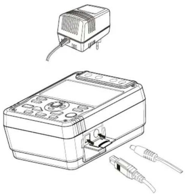
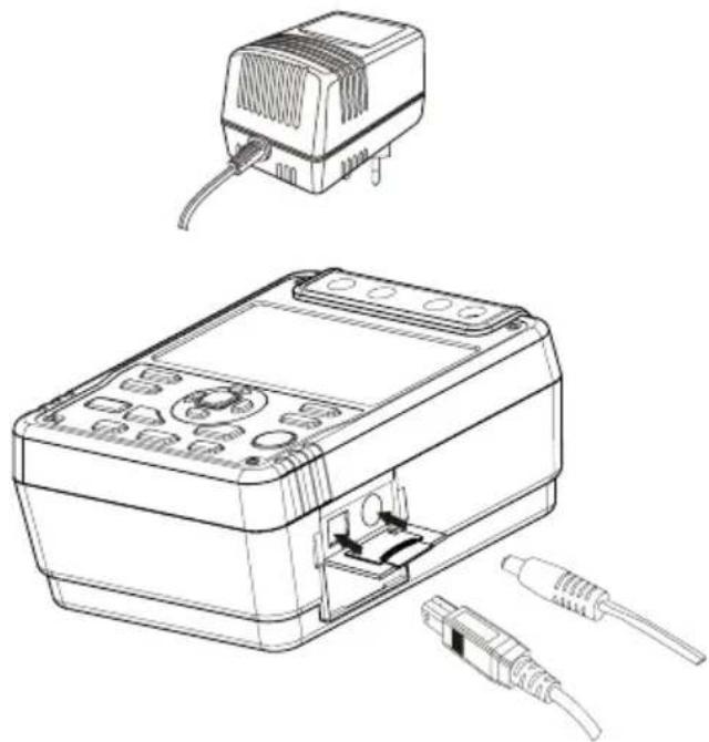
The Use of Power Adaptor
natural_image
Line drawing of a device with an attached electrical outlet and external connectors (no text or symbols)- Open the side safety shutter, then you will see there is a power adaptor input terminal.
- Make sure the Meter is power off and insert the AM-50 power adaptor to the input terminal.
- It is highly recommended to take out all the batteries when you are using the power adaptor.
- Make sure the Meter is power off when you disconnect the AM-50 power adaptor from the Meter.
USB Interface
natural_image
Technical line drawing of a device with an external connector and internal components (no text or symbols)- Install the provided software, the installation guide can be found in the CD disk.
- Open the side safety shutter, then you will see there is a USB port.
- Insert the provided USB cable to the Meter's USB port and the other end to the computer.
Battery Saver (Sleep Mode)
The Meter goes into sleep mode when the Meter is in idle for 15 minutes. Press ON/OFF for 1 second again to turn on the Meter.
Battery Indication
| Battery Indicator Battery Voltage | |
 | 10V or less. The battery is empty, don't use the Meter as it cannot guarantee accuracy. |
 | 10V~10.5V. The battery is nearly empty, replacing battery is necessary. At this status, the Meter can still do 500V and 1000V output measurement, accuracy will not be affected. |
 | 10.6V~11.5V :Good |
 | 11.6V or more :Full |
Safety and Compliances
| Certification | CE |
| Compliances | IEC 61010 CAT III 600V overvoltage and double insulation standard, Pollution degree II IEC 61326-1 |
Physical Specifications
| Display (LCD) | Digital: 9999 countsAnalog bar graph. |
| Operating Temperature 0°C ~ 40°C (32°F ~ 104°F ) | |
| Storage Temperature -20°C ~ 60°C (-4 °F ~ 152°F ) | |
| Relative Humidity | Operating Relative Humidity ≤ 85%Storage Relative Humidity ≤ 90% |
| Battery Type | 8pcs X 1.5V (LR14) batteries or power adaptor (input voltage 120V, 60Hz, 75mA, output DC14V, 1.0A).Power adaptor is included. |
| Dimensions (H x W x L) 202 x | 155 x 94 mm |
| Weight Approx. 2kg (4.4 Lbs) | (including battery) |
General Specifications
| Range Auto | |
| Overloading Display OL | on insulation resistance range |
| Battery Indicator | Display □ □ □ □ □ |
| Icon Display Equips with function and battery indicator icons. | |
| Current Consumption | Maximum: around 1.0AAverage: around 20mA |
Feature Summary
| Display Backlight Bright back | blacklight for clear readings in poorly lighted areas. |
| Computer connection Via USB interface. | |
| Data Logging and Recall 18 | |
| Autorange The Meter automatically selects best range | |
| Warning | △ and red light will on. |
| Voltage Auto release voltage | |
| COMP Measurement | Use the Compare function to set a pass/fail compare level for the insulation measurements. |
| PI Measurement | Polarization Index is the ratio of insulation resistance. You can pre-set two point of times and automatically carry out the measurement. |
| TIME To carry out measurement by setting a specified time within 15 minutes. | |
Detailed Accuracy Specifications
Accuracy: ±([a% of reading] + [number of least significant digits]), guarantee for 1 year.
Operating temperature: 18°C \~28°C
Relative humidity: 45\~75%RH
A. Voltage Measurement
| DC Voltage AC Voltage | ||
| Measurement Range ±30 ~ ±600V 30V~600V (50/60Hz) | ||
| Resolution 1V | ||
| Accuracy ±(2%+5), when voltage between 30-100V (5/60Hz) the accuracy is ±(2%+8) | ||
B. Insulation Resistance Measurement
| Output Voltage | 500V 1000V 2500V 5000V | |||
| Display Range | 0.5MΩ ~20GΩ | 2M Ω~40GΩ | 5MΩ ~100GΩ | 100MΩ ~1000GΩ |
| Open Circuit Voltage | DC 500V 0%~+ 20% DC 1000V 0%~+ 20% DC 2500V 0%~+ 20% DC5000V 0%~+ 20% | |||
| Test Current 1mA~1.2mA @ 500k Ω | 1mA~1.2mA @ 1MΩ | 1mA~1.2mA @ 2.5MΩ | 1mA~1.2mA @ 5MΩ | |
| Accuracy | 0.50M ~99.9M : ±(3%+5)100M ~9.99G : ±(5%+5)10.0G ~20.0G : ±(10%+5) | 2.0M ~99.9M : ±(3%+5)100M ~9.99G : ±(5%+5)10.0G ~40.0G : ±(10%+5) | 5.0M ~99.9M : ±(3%+5)100M ~9.99G : ±(5%+5)10.0G ~100G : ±(10%+5) | 10.0M ~29.9M : (For reference only)30.0M ~99.9M : ±(3%+5)100M ~9.99G : ±(5%+5)10.0G ~99.9G : ±(10%+5)Above 100G : [±(20%+5) Humidity:Below 50%] |
| Short Circuit | Less than 2.0mA | |||
OPERATING CAUTION
At any output voltage, when the tested resistance is less than 10M Ohm, the measurement shall be limited to 10 seconds maximum.
MAINTENANCE AND REPAIR
If there appears to be a malfunction during the operation of the meter, the following steps should be performed in order to isolate the cause of the problem.
- Check the battery. Replace the battery immediately when the symbol "☐" appears on the LCD.
- Review the operating instructions for possible mistakes in operating procedure.
Except for the replacement of the battery, repair of the meter should be performed only by a Factory Authorized Service Center or by other qualified instrument service personnel. The front panel and case can be cleaned with a mild solution of detergent and water. Apply sparingly with a soft cloth and allow to dry completely before using. Do not use aromatic hydrocarbons, Gasoline or chlorinated solvents for cleaning.
- Periodically wipe the case with a damp cloth and mild detergent. Do not use abrasives or solvents.
- To clean the terminals with cotton bar with detergent, as dirt or moisture in the terminals can affect readings.
- Turn the Meter to OFF when it is not in use.
• Take out the battery when it is not using for a long time.
- Do not use or store the Meter in a place of humidity, high temperature, explosive, inflammable and strong magnetic field.
• If the Meter is wet, dry it before use.
⚠ WARNING!
- Do not attempt to repair or service your Meter unless you are qualified to do so
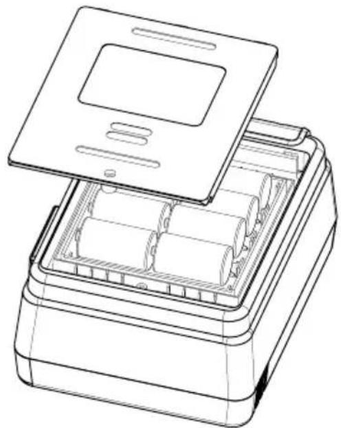
Replacing the Battery
natural_image
Line drawing of an open battery pack with lid and internal compartments (no text or symbols)WARNING!
To Avoid Electric shock, remove all the test leads from the Meter before replacing the batteries.
⚠ OPERATING CAUTION!
- Don't mix old and new batteries.
• Make sure the polarity is correct when installing batteries. - Do not use the Meter if the battery indicator (☐) shows a battery empty condition
- Do not carry out measuring with the battery compartment is open.
Follow the shown picture and proceed as follows to replace the battery:
- Turn the Meter to OFF and remove all connections from the terminals.
- Remove the screw from the battery compartment, and separate the battery
• compartment from the case bottom. - Replace with 8pcs of new 1.5V (LR14) batteries.
- Rejoin the case bottom and battery compartment, and reinstall the screw.
Software Installation
A. System Requirements
Installation of AMB-50 Interface Program requires below hardware and software specifications:
- An IBM PC or equivalent computer with 80486 or higher processor and a display with 800x600 resolution or better.
- Microsoft Windows 98 system or above.
• Minimum 8MB of RAM. - CD_ROM drive.
- USB port.
- A mouse or other pointing device supported by windows.
B. Install AMB-50 Interface program
To install AMB-50 Interface Program, please follow below instructions:
Before installing AMB-50 interface program, make sure that the computer is running Window 98 operating system or above.
-
- Insert the provided CD disk into CD-ROM drive.
-
Double-click the My Computer icon from the Windows desktop.
- Locate and double-click the CD-ROM drive from the window.
- Double-click "AMB-50 setup" folder.
- Double-click the file Setup.exe to start installation.

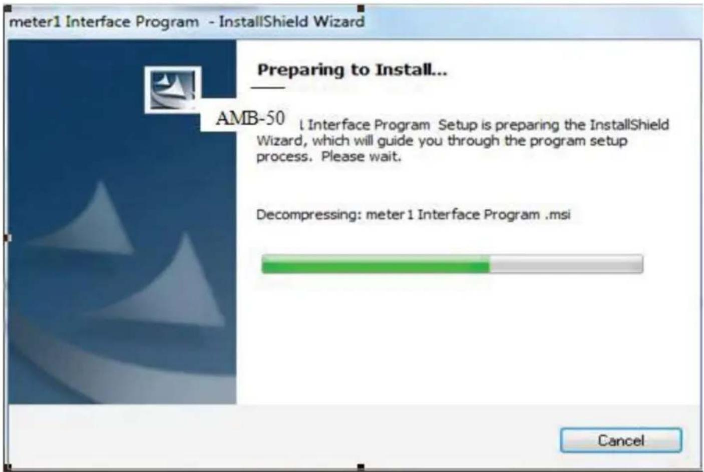
- Follow the on-screen installation instructions.
Note: Select "AMB-50" if you are asked to select which program to be installed.
Otherwise continue to proceed with the on-screen installation instruction
- The installation program will automatically create a AMB-50 folder and create a AMB-50 Interface Software short-cut on your desktop.
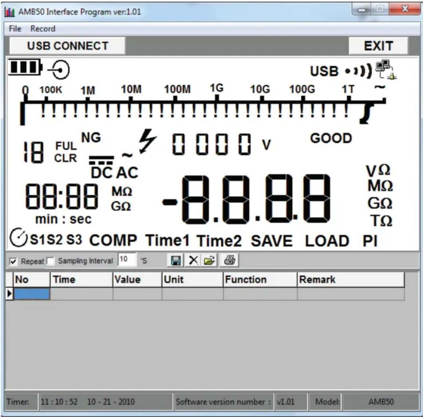
C. Use AMB-50 Interface program
- Connect the USB Interface Cable to the Meter (connection port besides DC power adaptor connector on the Meter) and connect the other end of USB Interface cable to the computer.
- From the Windows Start menu, choose Programs > DMM > AMB-50 or double click AMB-50 shortcut on desktop.
- Press USB button on the Meter (USB symbol will display on the upper-right corner of the screen on the Meter).
- Click "USB CONNECT" from menu bar to establish the connection, the icon will be displayed.
- Click EXIT to close the software
User's Guide
Get Started:
To run the AMB-50 Interface Program, please follow below instructions:
- Connect the USB Interface Cable to the Meter (connection port besides DC power adaptor connector on the Meter) and connect the other end of USB Interface cable to the computer.
- From the Windows Start menu, choose Programs > DMM > AMB-50 or double click shortcut on desktop.
- Press USB button on the Meter (USB symbol will display on the upper-right corner of the screen on the Meter).
- Click "USB CONNECT" from menu bar to establish the connection, the icon will be displayed.
- Click EXIT to close the software
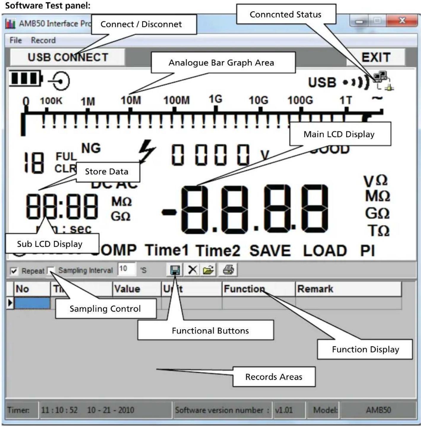
Data Recording Operations
While connected, you can select the following functions by clicking the corresponding icon or the menu bar
Repeat: Tick the box to activate the repeated measurement function, or un-tick the box to disable the function. The repeated measurement results are shown in below screen
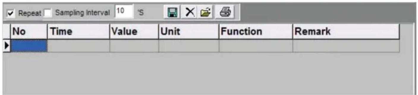
Sampling Interval: Click to enable sampling interval function, or unclick to disable the function. Enter the sampling interval's time in second(s) (1 to 999999999).
Note: When sampling interval is not specified, the sampling rate for repeated measurement is per second.
Function:

Save as: save measurement data(*.txt,*.xls,*.db).

Delete: delete all the displayed measurement data.

Open files: read measurement data from saved file (*.db).

Print: print the measurement data in report format.
File
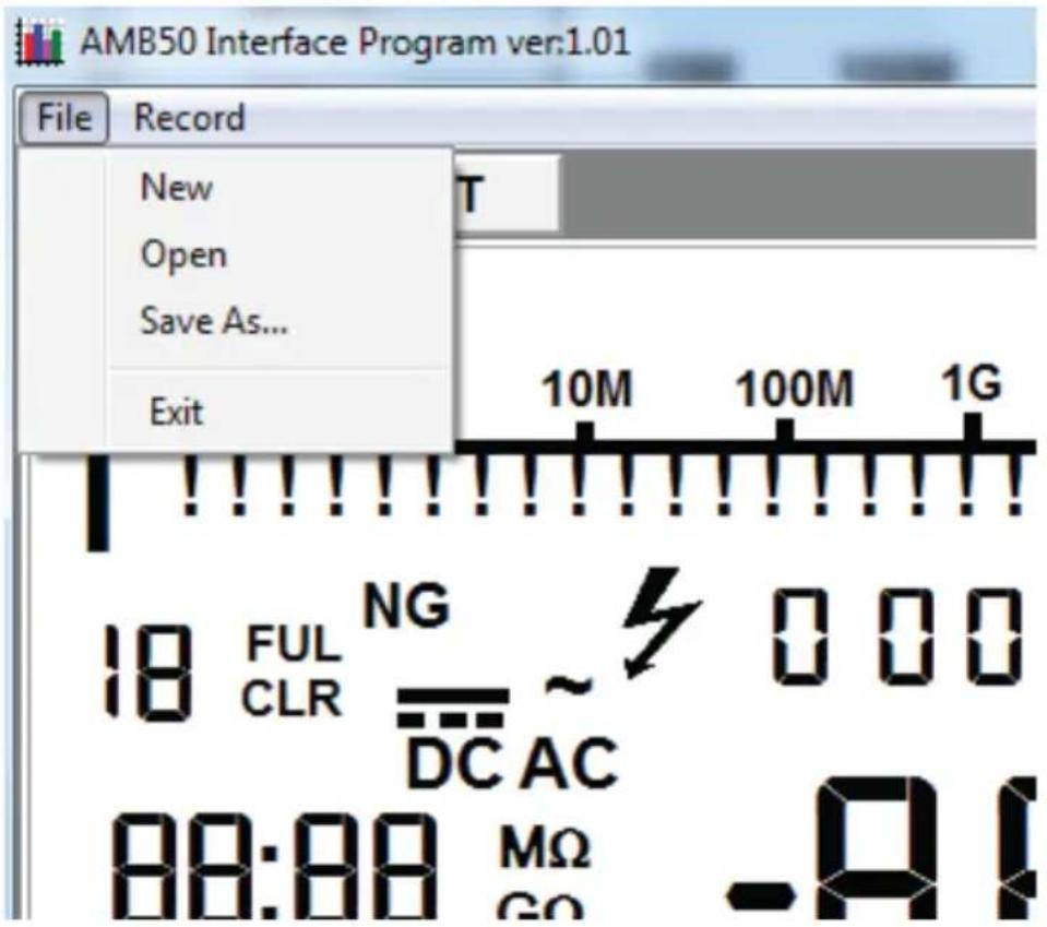
1. New
clear unsaved measurement data.
2. Open
read measurement data from saved file (*.db).
3. Save As
save measurement data(*.txt,*.xls,*.db)
4. Exit
exit the program.
Previous viewed files:
Maximum previous viewed files will be listed under File tab. Click the file name under File tab to open the file.
Record
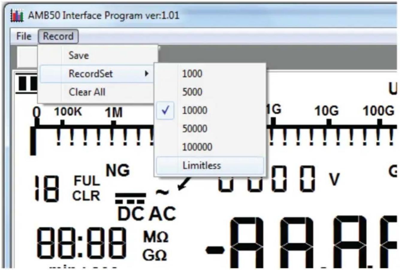
- Save
Save all the current measurement records to file (*.txt, *.xls, *.db)
2.RecordSet
Set the maximum numbers of measurement.
3.Clear all
Delete all unsaved records.
AMPROBE®
AMB-50
Amprobe Test Tools Amprobe Test Tools
Everett, WA 98203 Mississauga, Ontario L4Z 1X9
Tél. : 877-AMPROBE (267-7623) Tél. : 905-890-7600
natural_image
Line drawing of a device with an open base, connected to a plug and cable (no text or symbols)natural_image
Technical line drawing of a device with an open rear panel and two connectors (no text or symbols)natural_image
Line drawing of an open battery pack with a lid and internal compartments (no text or symbols)⚠ AVERTISSEMENT !

Function (Fonction):

1. New
Previous viewed files
Amprobe Test Tools Amprobe Test Tools
Everett, WA 98203 Mississauga, ON L4Z 1X9
Tel.: 877-AMPROBE (267-7623) Tel.: 905-890-7600
Softwareinstallation....13
VORSICHT!
natural_image
Line drawing of a device with an attached power outlet and internal components (no text or symbols)natural_image
Technical line drawing of a device with an open base and two connected components (no text or symbols)natural_image
Line drawing of a device with an open lid and internal compartments (no text or symbols)⚠️WARNUNG!
Save as (Speichern unter): Messdaten speichern (*.txt, *.xls, *.db).
- New (Neu)
- Save as (Speichern unter)
Messdaten speichern (*.txt, *.xls, *.db).
- Exit (Beenden)
Amprobe Test Tools Amprobe Test Tools
Everett, WA 98203 Mississauga, ON L4Z 1X9
Tel: 877-AMPROBE (267-7623) Tel: 905-890-7600
ATTENZIONE
ATTENZIONE
natural_image
Line drawing of a device with an open box, cable connectors, and a separate package (no text or symbols)natural_image
Technical line drawing of a device with an open base, internal components, and external connectors (no text or symbols)natural_image
Line drawing of an open battery pack with lid and internal compartments (no text or symbols)⚠ AVVERTENZA
1. New
Amprobe Test Tools Amprobe Test Tools
Everett, WA 98203 Mississauga, Ontario L4Z 1X9
Tel.: 877-AMPROBE (267-7623) Tel.: 905-890-7600
natural_image
Line drawing of a device with an open box, cable connectors, and a separate package (no text or symbols)natural_image
Technical line drawing of a device with an open base, internal components, and external connectors (no text or symbols)natural_image
Line drawing of an open battery pack with lid and internal compartments (no text or symbols)ADVERTENCIA
1. New
Visit www.Amprobe.com for
- Catalog
- Application notes
• Product specifications - User manuals


- 5000V Insulation Resistance Tester
- Users Manual
- AMPROBE®
- AMB-50
- Limited Warranty and Limitation of Liability
- Repair
- In-Warranty Repairs and Replacement – All Countries
- Non-Warranty Repairs and Replacement – US and Canada
- Non-Warranty Repairs and Replacement – Europe
- CONTENTS
- UNPACKING AND INSPECTION
- INTRODUCTION
- SAFETY INFORMATION
- ⚠️DANGER!
- ⚠ WARNING!
- ⚠️ CAUTION!
- OPERATING CAUTION!
- Note
- a) Continuous Measurement
- b) Timed Measurement
- c) Polarization Index (PI) Measurement
- Information
- d) Compare Function
- The Use of Power Adaptor
- USB Interface
- Battery Saver (Sleep Mode)
- Battery Indication
- Detailed Accuracy Specifications
- OPERATING CAUTION
- MAINTENANCE AND REPAIR
- Replacing the Battery
- WARNING!
- ⚠ OPERATING CAUTION!
- Software Installation
- System Requirements
- Install AMB-50 Interface program
- Use AMB-50 Interface program
- User's Guide
- Get Started:
- Data Recording Operations
- Function:
- File
- New
- Open
- Save As
- Exit
- Previous viewed files:
- Record
- ⚠ AVERTISSEMENT !
- Function (Fonction):
- Previous viewed files
- VORSICHT!
- ⚠️WARNUNG!
- ATTENZIONE
- ⚠ AVVERTENZA
- ADVERTENCIA
- Visit www.Amprobe.com for
Brand : Amprobe
Model : AMB50
Category : Measuring equipment