
PT390 - Printer OKI - Free user manual and instructions
Find the device manual for free PT390 OKI in PDF.

| Product Type | Direct Thermal Printer |
| Brand | OKI |
| Model | PT390 |
| Print Method | Direct Thermal Line Printing System |
| Resolution | 8 dots/mm (0.125 mm) |
| Maximum Printing Speed | 300 mm/s (monochrome), 115 mm/s (two-color) |
| Supported Paper Widths | 83 mm, 80 mm, 70 mm, 60 mm, 58 mm |
| Interfaces | Parallel (IEEE1284), USB 1.1, RS-232C, LAN (10BASE-T/100BASE-TX) |
| AC Adapter | Model KA02951-0120, input 100-240 V AC, output 24 V DC / 1.5 A |
| Power Consumption | Standby 4.5 W max, operating 44 W average |
| Operating Temperature | 0 °C to 40 °C (printing guaranteed 5 °C to 35 °C) |
| Operating Humidity | 10 % to 95 % RH non-condensing (printing 10 % to 85 % RH) |
| Thermal Head Life | 150 km (monochrome), 75 km (two-color) or 150 million pulses |
| Cutter Life | Up to 2,000,000 cuts (75 µm paper, partial cut) |
| Drawer Kick-Out Connector | 6-pin, cash drawer compatible |
| Maintenance Functions | Cleaning of platen, thermal head, cutter blade |
| Special Modes | Print test, hexadecimal dump, custom settings |
| Supplied Accessories | CD thermal paper roll, instruction manual, AC adapter, power cord |
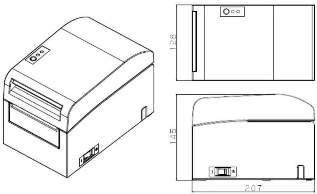
| Dimensions | Approx. 180 × 150 × 80 mm (estimated from diagrams) |
| Approximate Weight | Approx. 1.2 kg (without paper) |
Frequently Asked Questions - PT390 OKI
User questions about PT390 OKI
0 question about this device. Answer the ones you know or ask your own.
Ask a new question about this device
Download the instructions for your Printer in PDF format for free! Find your manual PT390 - OKI and take your electronic device back in hand. On this page are published all the documents necessary for the use of your device. PT390 by OKI.
USER MANUAL PT390 OKI
Every effort has been made to ensure that the information in this document is complete, accurate, and up-to-date. The manufacturer assumes no responsibility for the results of errors beyond its control. The manufacturer also cannot guarantee that changes in software and equipment made by other manufacturers and referred to in this manual will not affect the applicability of the information in it. Mention of software products manufactured by other companies does not necessarily constitute endorsement by the manufacturer.
While all reasonable efforts have been made to make this document as accurate and helpful as possible, we make no warranty of any kind, expressed or implied, as to the accuracy or completeness of the information contained herein.
All rights are reserved by Oki Data Corporation. Unauthorized copying, transferring, translating, or related actions are prohibited. You must obtain written permission from Oki Data Corporation before doing any of the above.
© 2011 Oki Data Corporation
OKI is a registered trademark of Oki Electric Industry Co., Ltd.
Energy Star is a trademark of the United States Environmental Protection Agency.
Microsoft, Windows, Windows Server and Windows Vista are registered trademarks of Microsoft Corporation.
Apple, Macintosh, Rosetta, Mac and Mac OS are registered trademarks of Apple Inc.
Other product names and brand names are registered trademarks or trademarks of their proprietors.

As an Energy Star Program Participant, the manufacturer has determined that this product meets the Energy Star guidelines for energy efficiency.

This product complies with the requirements of the Council Directives 2014/30/EU (EMC) and 2014/35/EU (LVD), 2014/53/EU (RED) and 2011/65/EU(RoHS) as amended where applicable, on the approximation of the laws of the member states relating to Electromagnetic Compatibility, Low Voltage, Radio & Telecommunications Terminal Equipment, Energy related Products and Restriction on the use of certain Hazardous Substances in electrical and electronic equipment.
The following cables were used to evaluate this product to achieve EMC directive 2014/30/EU compliance and configurations other than this may affect that compliance.
| CABLE TYPE | LENGTH(METRE) | CORE SHIELD | |
| Power 2.0 | × | × | |
| USB 5.0 | × | √ | |
| Serial (25pin) | 15.0 | × | √ |
| Parallel 2.9 | × | √ | |
| LAN | 10.0 | × | × |
| Drawer 1.8 | × | × | |
WARNING! This is a class A product as defined in EN55022. In a domestic environment this product may cause radio interference, in which case the user may be required to take adequate measures.
MANUFACTURER
Oki Data Corporation,
4-11-22 Shibaura, Minato-ku,
Tokyo 108-8551,
Japan
For all sales, support and general enquiries contact your local distributor.
IMPORTER TO THE EU/AUTHORISED REPRESENTATIVE
OKI Europe Limited (trading as OKI Printing Solutions)
Blays House
Wick Road
Egham
Surrey, TW20 0HJ
United Kingdom
For all sales, support and general enquiries contact your local distributor.
ENVIRONMENTAL INFORMATION

Description of Safety symbols displayed on the equipment
| No. | Symbol Description | |
| 1 | main | "ON" (power)To indicate connection to the mains, at least for mains switches or their positions. |
| 2 |  | Stand-byTo identify the switch or switch position by means of which part of the equipment is switched on in order to bring it into the stand-by condition. |
| 3 |  | General warning/cautionTo identify a general warning/caution. |
| 4 |  | Caution, hot surfaceTo indicate that the marked item can be hot and should not be touched without taking care. |
| 5 |  | Direct currentTo indicate on the rating plate that the equipment is suitable for direct current only; to identify relevant terminals. |
| 6 | swon | Alternating currentTo indicate on the rating plate that the equipment is suitable for alternating current only; to identify relevant terminals. |
TABLE OF CONTENTS
- Appearance and Names of Components ....4
- AC Adapter and Thermal Roll Paper 6
2-1. AC adapter 6
2-2. Paper specification (Thermal paper) 6
2-3. Recommended Thermal Paper 7
- Preparations 9
3-1. Connecting Interface Cable 9
3-2. Connecting the drawer kick cable 13
3-3. Connecting the AC Adapter 14
3-4. Disconnecting the AC Adapter 16
3-5. Turning on the Power 17
3-6. Installing the Printer Software 17
- Inserting Paper for Printing 18
4-1. Replacing paper 18
- Control Panel 27
5-1. Control Panel 27
5-2. Error Indications 27
- Preventing and Clearing Paper Jams 29
6-1. Preventing Paper Jams 29
6-2. Clearing a Paper Jam 29
- Troubleshooting 30
7-1. Power-on Problems and Errors 30
7-2. Cutter-related Problems 30
7-3. Printing-related Problems 31
- Regular Cleaning 32
8-1. Cleaning the Paper Holder and Paper Transport 32
8-2. Cleaning the Platen Roller 33
8-3. Cleaning the Thermal Head 36
8-4. Cleaning the Cutter Blade and Frame 37
- Notes on Use 43
Appendix A: Specifications 48
A-1.General Specifications 48
A-2.Cutter Specifications 50
A-3.Paper Supply Specifications 50
A-4.Interface Specifications 50
A-5.Environment Specifications 51
A-6.Specifications of Reliability 52
Appendix B: Interface 53
B-1.Parallel Interface 53
B-2.Dual Interface 55
B-3.LAN Interface 56
B-4.Drawer Kick Connector 58
B-5.Specifications of Power Supply 60
Appendix C: Special Modes 61
C-1.Test Printing 61
C-2.Hex Dump 62
C-3.Setting Up the Printer 63
C-4.Setup Items 85
C-5.Sample Print 91
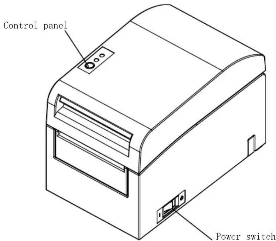
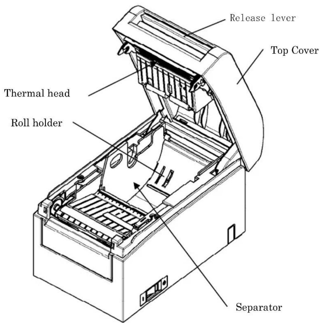
1. Appearance and Names of Components
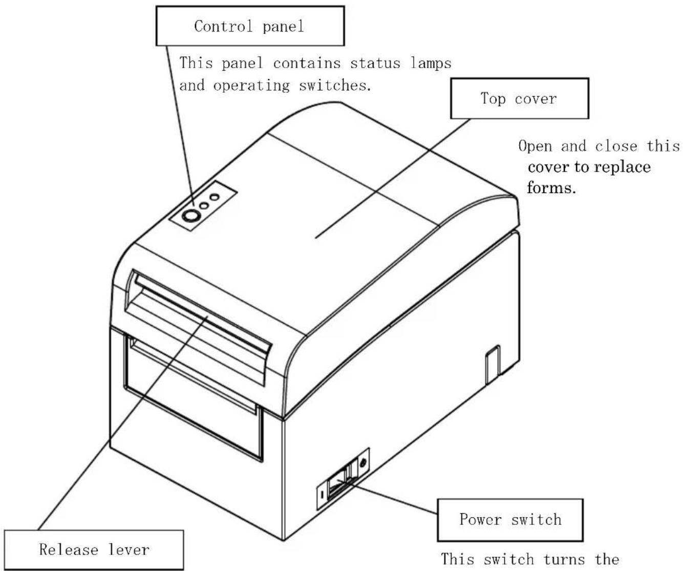
Pull up the release lever to open the top cover.
This switch turns the printer power on and off.
Appended goods
Thermal paper CD

natural_image
Simple geometric diagram with concentric circles and a diagonal line inside a diamond shape (no text or symbols)MANUAL PRINTER DRIVER UTILITY SOFT

natural_image
Simple geometric diamond shape with no text or symbolsInstruction sheet Safety warranty sheet

natural_image
Simple geometric diamond shape outline with no text or symbols
natural_image
Technical line drawing of a mechanical device with a coiled spring and housing (no text or symbols)AC adapter Power cable
natural_image
Abstract line drawing with concentric curved lines and a small figure at the bottom (no text or symbols)2. AC Adapter and Thermal Roll Paper
2-1. AC adapter
Only use the AC adapter specified below.
Model name: KA02951-0120
Input: 100 to 240V AC, 50/60Hz-
Output: DC24V±5%, 1.5A
Caution: Only use authorized AC adapters.
⚠ Caution: Do not use the bundled AC adapter and Power cable for any electrical equipment other than this printer.
2-2. Paper specification (Thermal paper)
Be sure to use thermal roll paper that conform to the following specifications.
- Paper width: For paper 83mm wide, 83 ^0-1.0 mm 80mm wide, 80 ^0-1.0 mm For paper 60mm wide, 60 ^0-1.0 mm 58mm wide, 58 ^0-1.0 mm
- Outside diameter: For paper 75 to 90μm thick, φ102mm or less For paper 90 to 150μm thick, φ90mm or less
- Core diameter: For paper 75 to 90 m thick, 12± 0.5mm (inside) / 18± 0.5mm (outside)
For paper 90 to 150 m thick, 25.4± 0.5mm (inside) / 32± 0.5mm (outside)
- Printed surface: Outside of the roll - Treatment of end of paper: The roll paper must not be glued to the core. The end of the paper must also not be folded back.
Note: Do not use rolls that have rough sides or sides from which pieces of paper extrude. Using such rolls could cause a printer failure.
2-3. Recommended Thermal Paper
| Manufacturer | Product name | Quality characteristics Paper thickness | Density specification |
| Ltd. | PD160R | Monochrome thermal paper (high-grade preservation type) | 75μm |
| PD190R | Monochrome thermal paper (mid-grade preservation type) | 75μm | |
| Nippon Paper Industries Co., Ltd. | HD75 | Monochrome thermal label paper (normal type) | 150μm |
| Mitsubishi Paper Mills Limited | P220AE-1 | Monochrome thermal paper (normal type) | 150μm |
| PB670 Two-color thermal paper (red/black: normal type) | 75μm | ||
| PB770 Two-color thermal paper (blue/black: normal type) | 75μm | ||
Note: A recommended type of paper must be used. If a type of paper other than a recommended one is used, head damage, printing irregularities, or similar problems may occur.
Note: To use two-color thermal paper, set the print color to two colors from the printer setup menu or using the setup tool contained on the CD-ROM provided with the printer.
(See "C-3 Setting Up the Printer" in Appendix C, "Special Modes.")
* By setting the appropriate property (use Color on the Graphics tab) for printing with this printer driver, you can easily print in two-color mode without having to change the printer setup.
Note: Ruled lines or characters containing fine lines (e.g. a serif typeface) tend to have dull colors when they are printed on two-color thermal paper. For printing on two-color thermal paper, a thick font (e.g., a sans serif font) is recommended.
Note: Red or blue printing on two-color thermal paper has an inferior preservation characteristic that is equivalent to that of normal thermal paper.
Note : Printouts on label paper or thick paper may contain blurs or voids, depending on the humidity and other environmental conditions. Adjust the print speed and print density as appropriate for the type of paper used. (See "C-3 Setting Up the Printer" in Appendix C, "Special Modes.")
In particular, note that the paper transport accuracy may be negatively affected by printing a barcode in the top margin at the beginning of paper transport or in the Lower margin at the end of paper transport.
3. Preparations
No printer cable is provided with the product. Obtain a printer cable suitable for the product interface. If you have any questions, consult your dealer. Before connecting or disconnecting cables, make sure of the following:
1) The power to the printer and all other devices connected to the printer is turned off.
2) The AC adapter power cable has been unplugged from the outlet.
3-1. Connecting Interface Cable
Open the connector cover at the rear of the printer by pulling it up, and connect the interface cable to its rear connector socket. Close the cover after connecting the cable.
Note: If cables are arranged so that they extend from the rear or from the rear on the right side, remove the inserts in the connector cover or the cover with nippers or a similar tool. Unless the inserts are removed in this case, the cables may be damaged and cause a failure.
For a unit with parallel interfaces
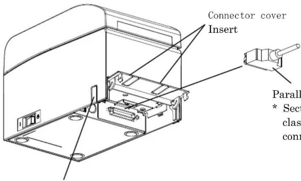
Insert
Parallel interface cable
* Secure the connector with clasps after making the connection.
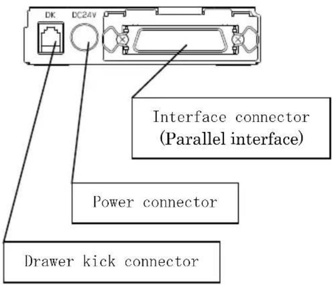
For a unit with Dual interface
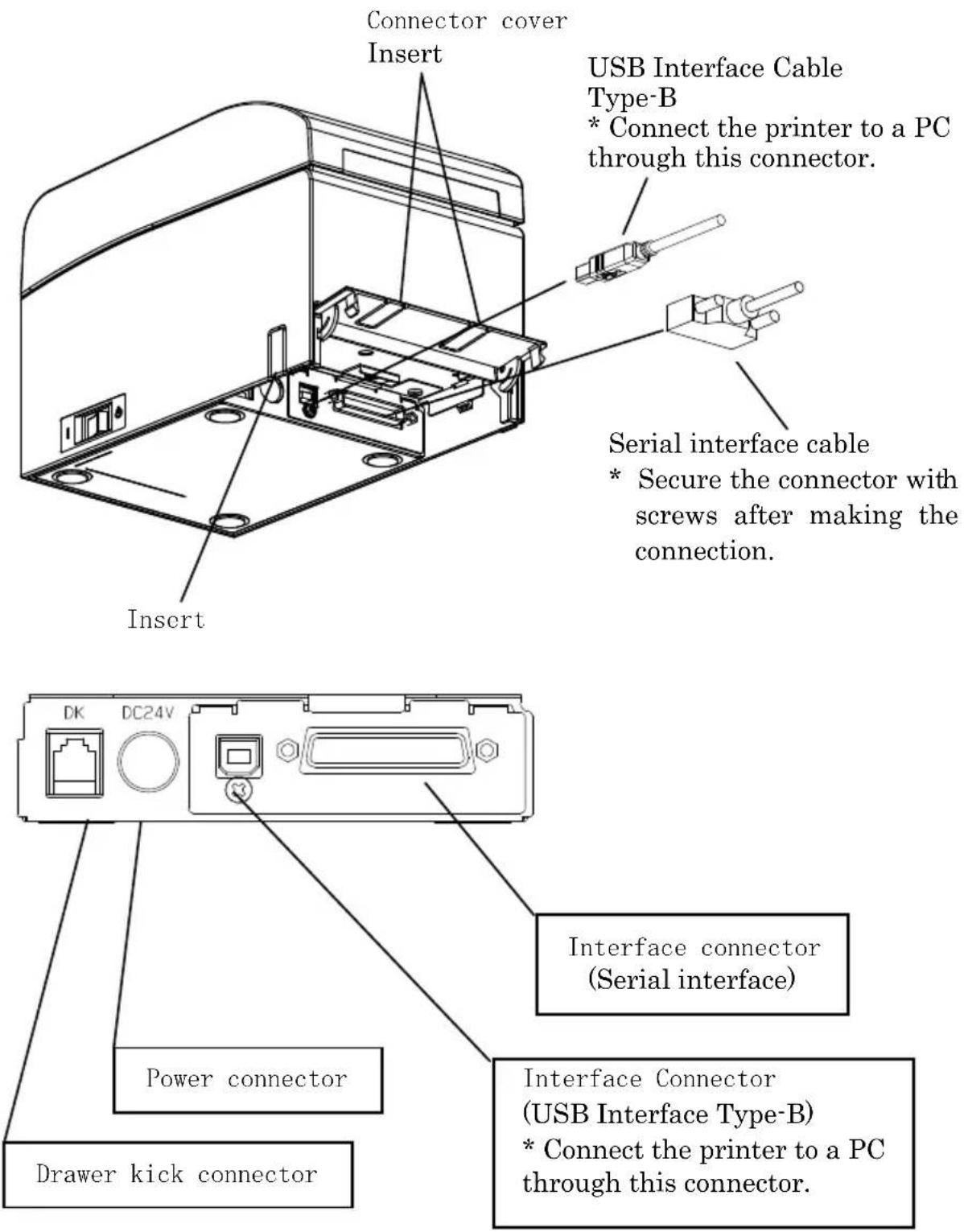
For a unit with LAN interface
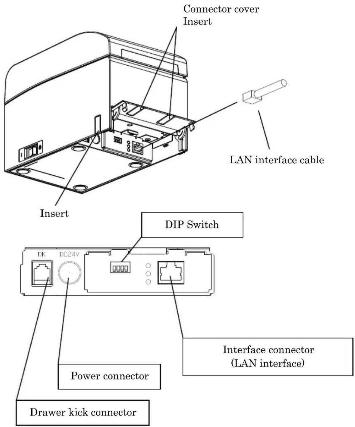
Caution: Do not touch the DIP switches during normal use. This may change the network settings, disabling normal printing.
Caution: If the device is installed vertically, the LAN cable may not usable due to its shape. Please check before installing.
⚠ Caution: The LAN interface cable must use the shield type.
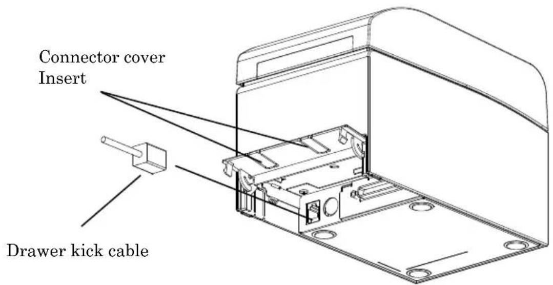
3-2. Connecting the drawer kick cable
Open the connector cover at the rear of the printer by pulling it up, and connect the drawer kick cable to its rear connector socket. Close the cover after connecting the cable.
Note : If the cable is arranged so that it extends from the rear, remove the inserts in the connector cover with nippers or a similar tool. Unless the inserts are removed in this case, the cable may be damaged and cause a failure.
Note : The drawer kick cable must not be used for a purpose other than for control of the drawer.
3-3. Connecting the AC Adapter
(1) Connect the AC adapter to the AC adapter power cable.
Note: To connect or disconnect the AC adapter, turn off the power switches of the printer and all the devices to be connected to the printer. Then, unplug the plug of the AC adapter power cable from the electrical outlet.
Note: Use only the specified AC adapter and specified AC adapter power cable.
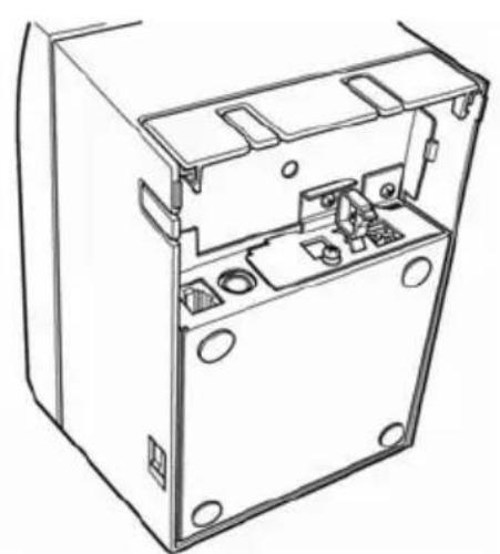
(2) Open the connector cover at the rear of the printer by pulling it up, and connect the AC adapter cable to the power socket. Close the cover after connecting the cable.
Note: To connect the AC adaptor, place the printer on its side to make the connection operation easier to perform.
Note: Remove notch of connector cover with Nipper, to maintain the space for the cable of AC adapter. Otherwise, the cable may be damaged and it way cause a failure.
natural_image
Technical line drawing of an open electronic device casing with internal components (no text or symbols)Printer placed on its side
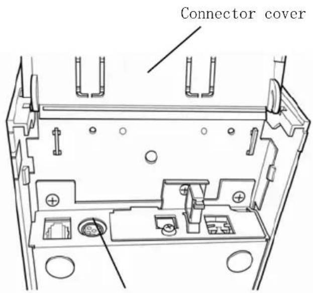
Power connector
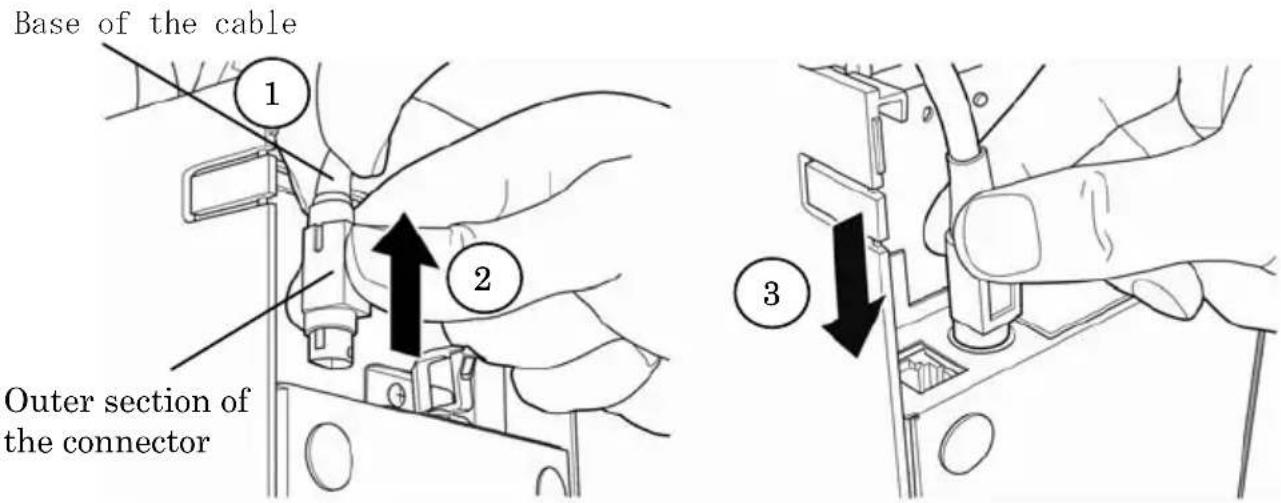
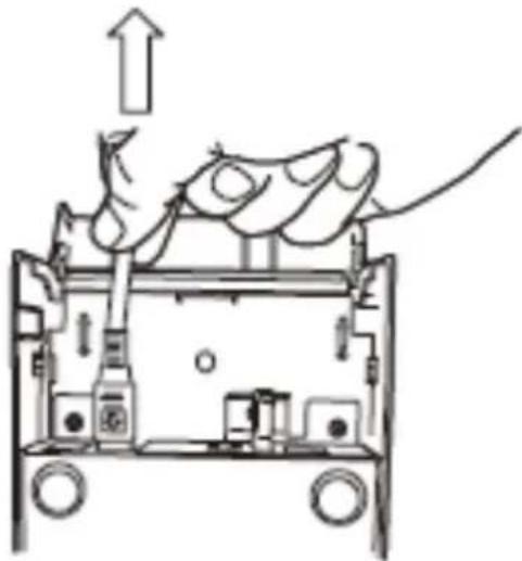
Note: To prevent the adaptor from slipping out, the connector section is designed to be tight to fit. When inserting, (1) pinch the base of the cable, (2) while sliding the outer section of the connector upwards, (3) and insert the connector until it locks in place with a “click” sound.
(3) Connect the plug of the power cable to electrical outlet.
natural_image
Diagram of a mechanical device with an upward arrow indicating motion or force, showing internal components and no readable text or symbols.(4) Plug the other end of the power cord into the power outlet.
3-4. Disconnecting the AC Adapter
To unplug the AC adapter cable, grasp the connector as shown in the picture below and pull it out. The lock mechanism of the connector will then disengage, and the cable can be unplugged easily. Conversely, forcibly pulling on the cable itself may damage the connector.
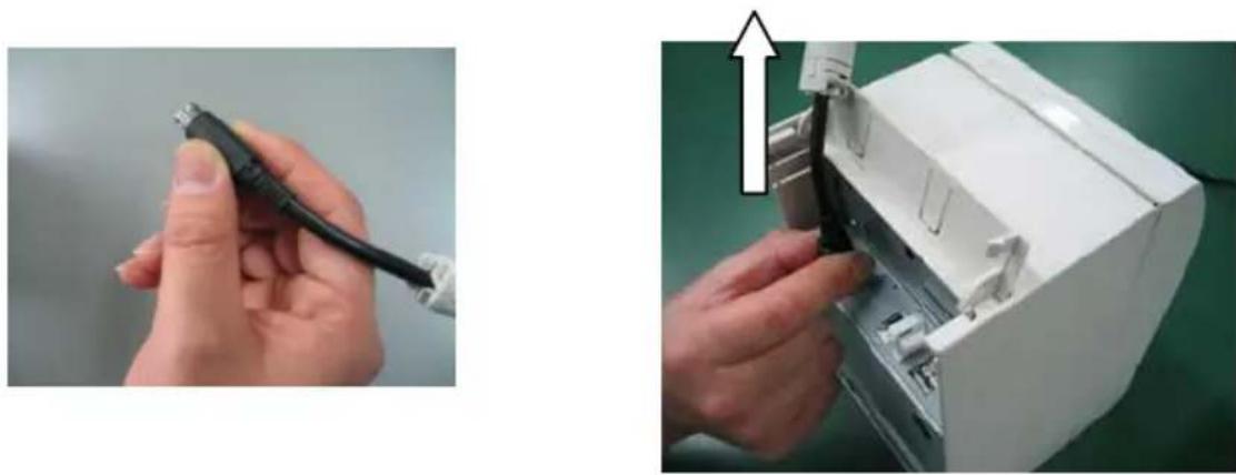
Note: Before disconnecting the AC adapter, switch off the printer and all devices connected to the printer, and also disconnect the power cable of the AC adapter from the outlet.
3-5. Turning on the Power
After the AC adapter is connected, turn on the power switch at the side of the printer. The POWER lamp on the control panel lights.
3-6. Installing the Printer Software
Referring to the "Installation Guide"
(\Manuals\PT390_InstallGuide1_en.pdf) contained on
the CD-ROM provided with the printer, install the printer driver and utility software.
4. Inserting Paper for Printing
4-1. Replacing paper
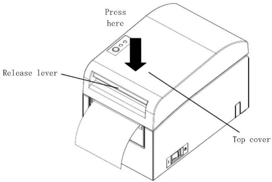
(1) Grasp the top cover, pull up the cover release lever, and open the top cover.
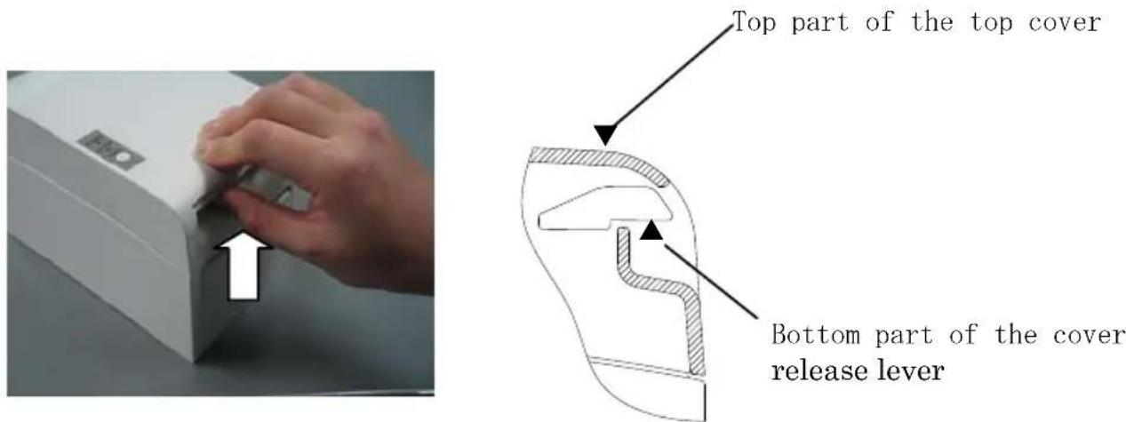
(2) When manipulating the top cover, note that the cover seems to lock in position before it is open completely. Make sure that the cover is really open completely as shown in the picture below.
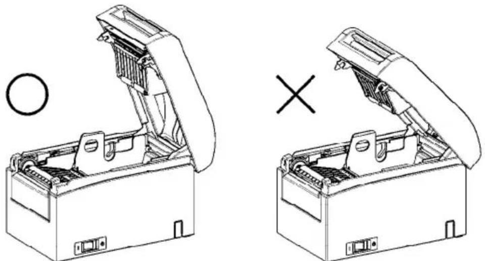
natural_image
Technical line drawing of two open tool holders with a circular head and cross symbol indicating assembly (no text or labels)Note: If the top cover is not open completely during maintenance, it may close inadvertently.
Note: Do not touch the thermal head. Doing so may result in damage from static electricity.
(3) Adjust the separator to the width of the roll paper. For roll paper with a width of 80 mm, the separator need not be removed. For roll paper with a width of 70, 60, or 58 mm, remove the separator and attach it again at the correct width. For roll paper with a width of 83 mm, remove the separator completely.
Note: At the time of shipment from the factory, the separator is set at a position appropriate for a paper width of 80 mm.
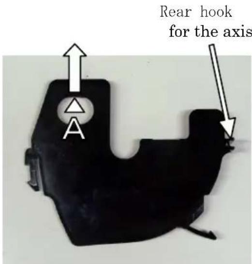
How to remove the separator
From the location indicated by A, lift the separator.
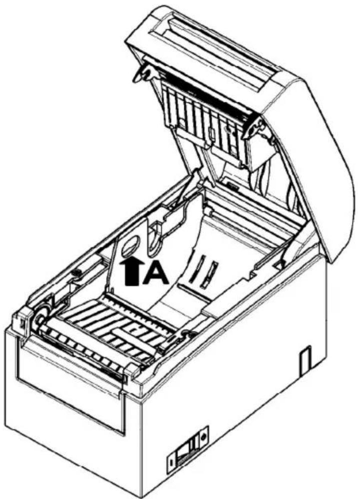
Separator
(4) Set the separator to a position appropriate for the width of the roll paper, as shown below.
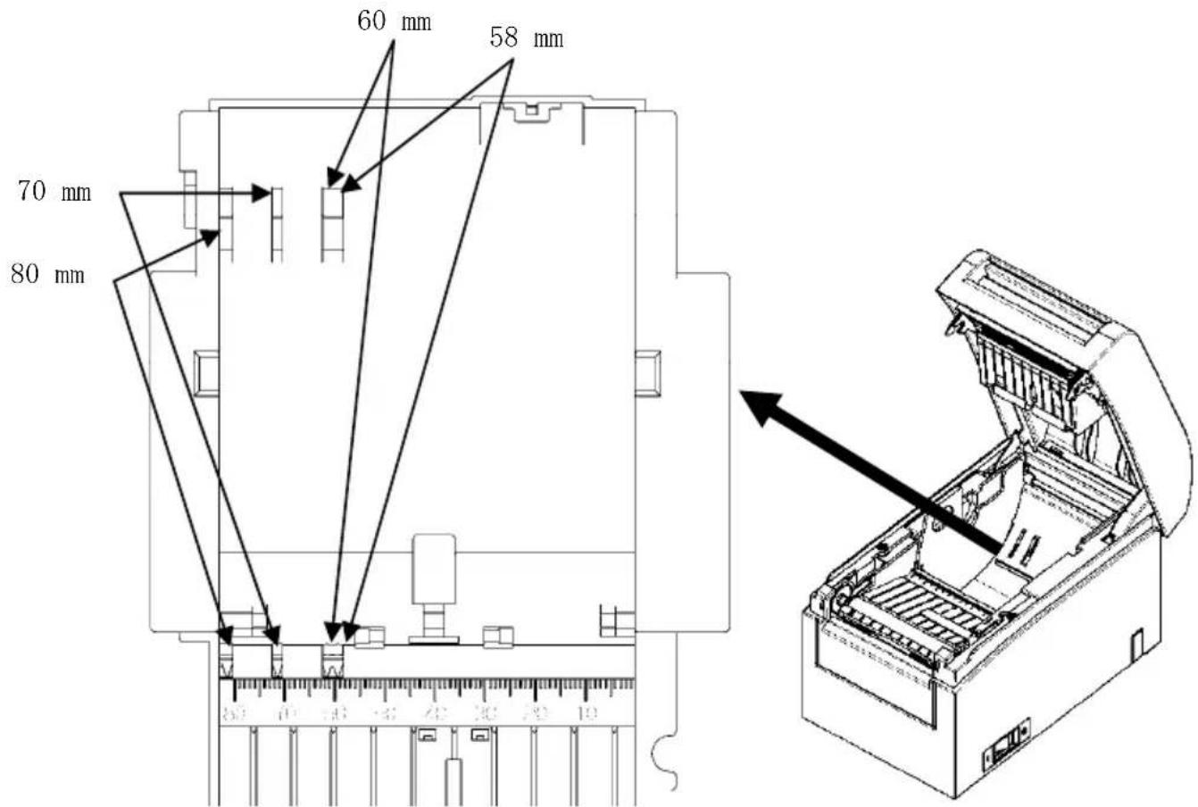
Separator setting in detail
Note : Adjust the separator to the width of the roll paper. To use roll paper with a width of 83 mm, remove the separator.
Note : When using roll paper with a width of 58 or 60 mm, take care not to set the separator at an angle.
Note : When replacing the separator, set a paper width appropriate to the print area, referring to Appendix C, "Special Modes."
(See "C-3 Setting Up the Printer" in Appendix C, "Special Modes.")
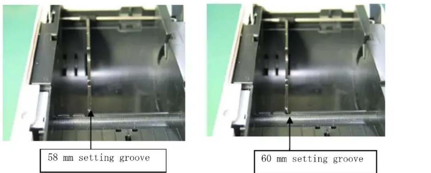
Roll papwidth of 58 mm
Roll paper width of 60
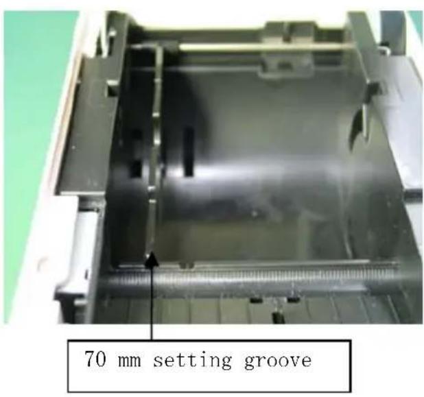
Roll paper width of 70 mm
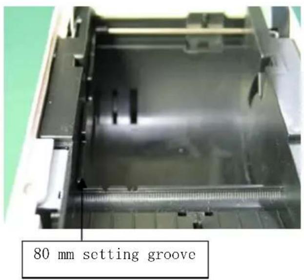
Roll paper width of 80 mm
How to attach the separator
Attach the separator at the rear hook for the axis.
Rear hook for the axis
Aligned horizontally
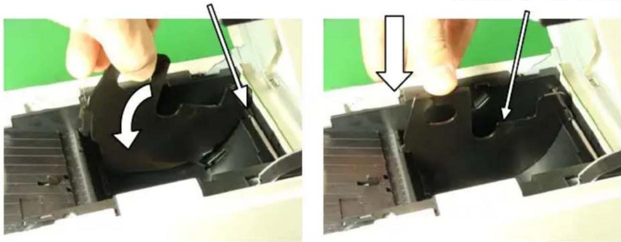
natural_image
Two-panel image showing a hand holding a black plastic component, with arrows indicating the process (no text or symbols present)Note : Push the separator down until it engages with an audible click, and confirm that the top of the separator is aligned horizontally.
Note : When using roll paper with a width of 58 or 60 mm, take care not to set the separator at an angle.
Note : When replacing the separator, set a paper width appropriate to the print area, referring to Appendix C-3 Setting Up the Printer" in Appendix C, "Special Modes."
(3) When using a new paper roll, remove the glued portion of the paper as well as the part to which adhesive tape is affixed.
Note: Since the glued portion of the paper should not be printed on, remove about one turn (about 40 cm) of the roll paper from the beginning so that none of the remaining paper has glue on it.
Any adhesive or other matter remaining from the glue may adhere to the thermal head and cause a problem, such as voids on printouts. Therefore, do not forget to remove the glued portion of the paper.
(4) From the front of the printer, pull out the end of the paper as shown below.
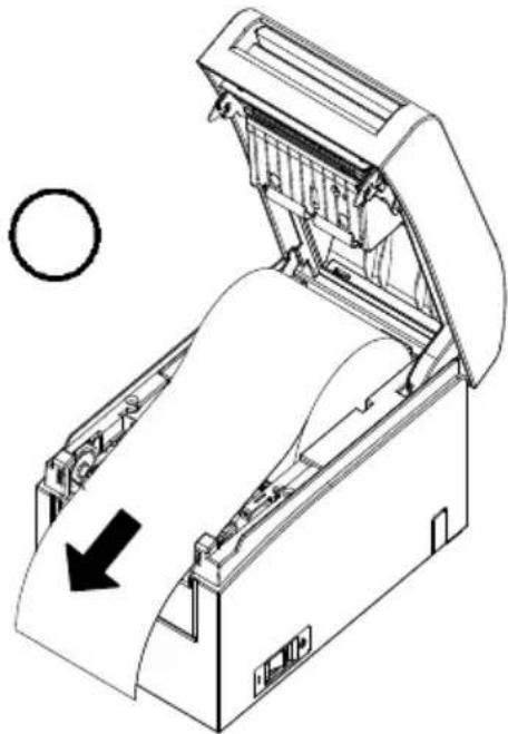
natural_image
Technical line drawing of a mechanical device with an open lid and internal components, showing no text or symbols.Note: Pull out the paper until enough of it protrudes past the front cover of the printer.
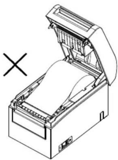
natural_image
Technical line drawing of an open industrial machine with a cross symbol indicating failure or invalid (no text or labels present)Paper not protruding from the front cover
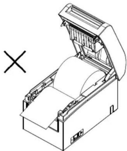
natural_image
Technical line drawing of an open industrial machine with a cross symbol indicating cancellation (no text or labels present)Roll paper inserted upside down
Note: Before loading a new roll, make sure that an old core does not remain in the roll holder. Leaving an old core will cause a paper-near-end error condition.
Note : The roll paper must have no deformities. Using roll paper such as that shown in the figure below may cause a paper jam, uneven printing, or other printing problem.
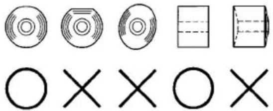
Note : If the loaded roll paper is loose (slack) as shown below, take up the slack before printing on the paper. Printing on roll paper that is loose may cause a paper jam, uneven printing, or other printing problem, which will prevent the printer from detecting paper near end conditions.

natural_image
Two abstract circular patterns with a circle and an 'X' symbol, no text or labels present.(5) Place the paper in the correct orientation, and carefully close the top cover.
Note : Place the paper in the correct orientation. If the top cover is closed while the paper is not correctly in place, a paper jam or misaligned printing might occur.
Note : To close the top cover, press it down near its center (the location pointed at in the figure below) until you hear the lock engage. If the cover is not completely locked, printing might be impossible.
5. Control Panel
5-1. Control Panel
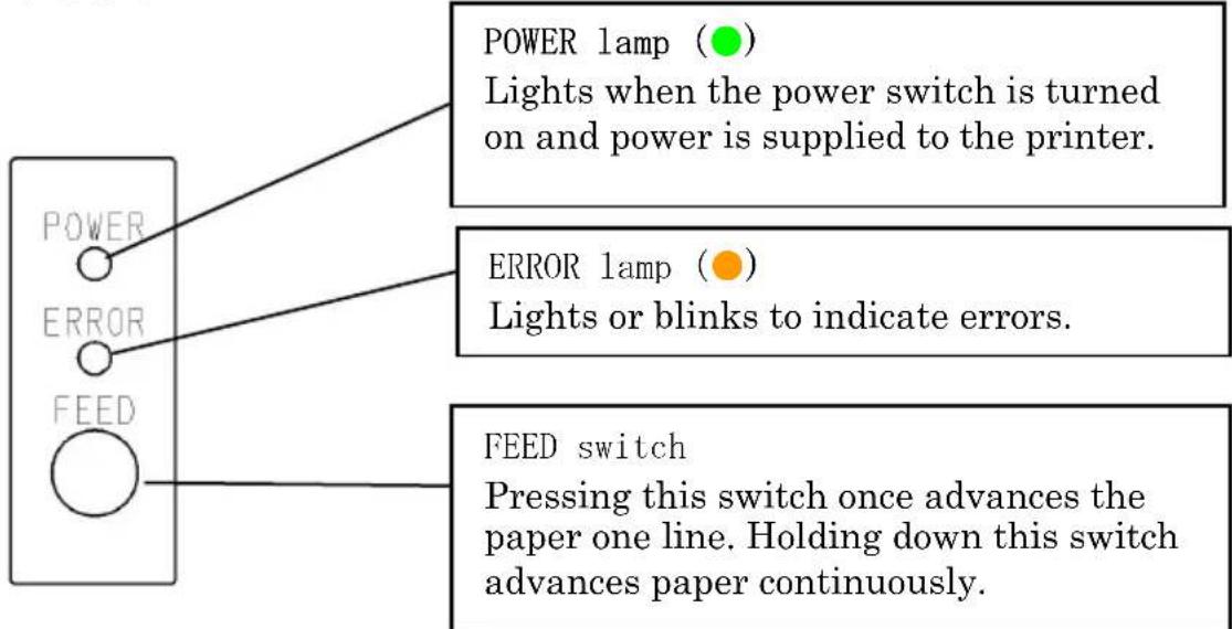
5-2. Error Indications
Recoverable errors
| Error condition | LED LAMP | Blinking pattern |
| No paper (paper end) | POWER (●) | Constantly on |
| ERROR (●) | Constantly on | |
| Cover open | POWER (●) | Constantly on |
| ERROR (●) | Constantly on | |
| Head hot (*1) | POWER (●) | Constantly on |
| ERROR (●) | Constantly on |
*1 Printing is suspended because of a high thermal head temperature.
| Error condition | LED LAMP | Blinking pattern |
| Paper near end | POWER (●) | Constantly on |
| ERROR (●) | ||
| Repeated blinking of the amber lamp four times in succession | ||
| Black mark error (*1) | POWER (●) | Constantly on |
| ERROR (●) | ||
| Repeated blinking of the amber lamp four times in succession |
*1 Applicable only if the printer supports sensing of black marks
Unrecoverable errors
| Error condition LED LAMP Blinking pattern | ||
| Internal error | POWER (●) | —●—●— |
| ERROR (●) | ●— | |
| Repeated pattern in which the green lamp blinks twice and the amber lamp blinks once | ||
| Head not installed | POWER (●) | —●—●—●— |
| ERROR (●) | ●— | |
| Repeated pattern in which the green lamp blinks three times and the amber lamp blinks once | ||
| Low voltage | POWER (●) | —●—●—●—●— |
| ERROR (●) | ●— | |
| Repeated pattern in which the green lamp blinks four times and the amber lamp blinks once | ||
| Over voltage | POWER (●) | —●—●—●—●—●— |
| ERROR (●) | ●— | |
| Repeated pattern in which the green lamp blinks five times and the amber lamp blinks once | ||
| Cutter functioning abnormally | POWER (●) | —●—●—●—●—●—●— |
| ERROR (●) | ●— | |
| Repeated pattern in which the green lamp blinks six times and the amber lamp blinks once | ||
| LF motor functioning abnormally | POWER (●) | —●—●—●—●—●—●—●— |
| ERROR (●) | ●— | |
| Repeated pattern in which the green lamp blinks seven times and the amber lamp blinks once | ||
6. Preventing and Clearing Paper Jams
6-1. Preventing Paper Jams
Do not touch the paper while the paper is being ejected or cut. Holding or pulling the paper by hand during ejection might cause a paper jam, incorrect cutting, or a feed error.
6-2. Clearing a Paper Jam
If a paper jam occurs, remove the jammed paper as follows:
(1) Turn off the printer power by turning off the power switch.
(2) Press the cover open lever down, and open the top cover.
(3) Pull out the jammed paper slowly toward the top while holding down the printer, as shown in the picture below.
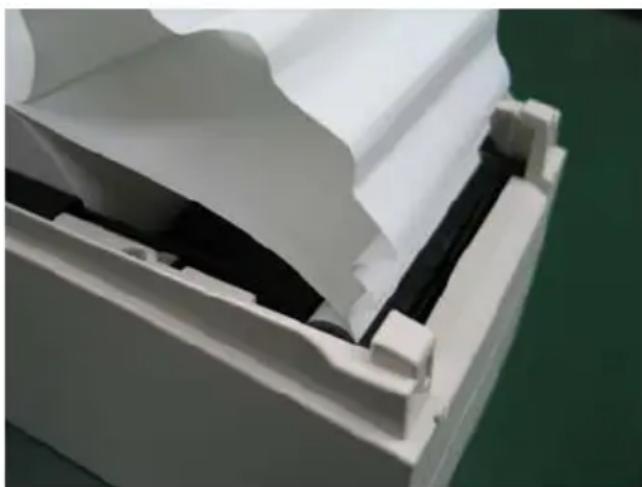
natural_image
Close-up of a white plastic panel with black insulation and a black inner component, placed on a green surface (no text or symbols visible)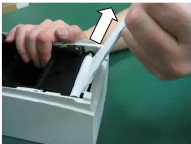
natural_image
Close-up of hands installing or adjusting a device into a white plastic container (no text or symbols visible)Note: Do not pull the paper with excessive force.
Note: Do not touch the thermal head. Doing so may result in damage from static electricity.
7. Troubleshooting
This chapter describes the appropriate action to be taken in cases where the printer is not operating correctly or fails to produce clean printouts.
7-1. Power-on Problems and Errors
| Symptom | Cause | Corrective |
| Although the power has been turned on, the POWER lamp on the control panel does not light and the printer does not start up. | (1) The power cable is disconnected.(2) The connector of the AC adapter is disconnected. | (1) Connect the power cable.(2) Connect the connector of the AC adapter. |
| The ERROR lamp on the control panel is lit, and the printer does not work. | (1) No paper is inserted.(2) The top cover is not closed completely.(3) The thermal head is at a high temperature. | (1) Insert paper.(2) Close the top cover completely.(3) Wait until the thermal head temperature decreases sufficiently. |
7-2. Cutter-related Problems
| Symptom | Cause | Corrective |
| Paper cannot be cut. | (1) The cutter blade is damaged or worn, or it has been used for too long.(2) Paper fragments or other foreign matter is stuck around the cutter blade or paper chute.(3) Adhesive matter is adhering to the cutter blade because of printing on label paper. | (1) Turn off the power, and ask for repairs.(2) Remove the paper fragments or foreign matter.(3) Clean the cutter blade to remove the adhesive matter. |
| The cutter does not return to the correct position. | Paper fragments or other foreign matter is stuck around the cutter blade or paper chute. | Remove the paper fragments or foreign matter. |
7-3. Printing-related Problems
| Symptom | Causes | Corrective action |
| Printing does not begin. | (1) The interface cable is disconnected or broken.(2) The printer setup is incorrect. | (1) Connect the interface cable correctly, or replace it.(2) Set up the printer correctly.Example: An incorrect baud rate is set.(See "C-3 Setting Up the Printer.") |
| The printing is too dark or blurry. | (1) The print density setting included in the printer setup is incorrect.(2) The thermal head is damaged. | (1) Adjust the print density and print speed settings of the printer so that they are appropriate to the paper.(See "C-3 Setting Up the Printer.")(2) Turn off the power, and ask for repairs. |
| Printed characters are thin (faint). | (1) The print density setting included in the printer setup is incorrect.(2) The thermal head is damaged. | (1) Adjust the print density and print speed settings of the printer so that they are appropriate to the paper.(See "C-3 Setting Up the Printer.")(2) Turn off the power, and ask for repairs. |
| The print density is uneven. | (1) Paper fragments or foreign matter is stuck on the heating elements of the thermal head.(2) The printer setup is incorrect.(3) Foreign matter is adhering to the platen roller.(4) The thermal head is damaged. | (1) Check and clean the thermal head.(2) Adjust the print density and print speed settings of the printer so that they are appropriate to the paper.Set up the printer correctly.(See "C-3 Setting Up the Printer.")(3) Remove the foreign matter from the platen roller.(4) Turn off the power, and ask for repairs. |
| Vertical marks appear on the printout. | (1) Foreign matter is stuck or caught on the paper transport.(2) Foreign matter is adhering to the thermal head(3) The thermal head is damaged. | (1) Clean the paper transport.(2) Clean the thermal head.(3) Turn off the power, and ask for repairs. |
8. Regular Cleaning
Printed characters may not be completely formed if paper residue, dust, or a similar material is present. To ensure proper printing, remove any paper residue and dust on the paper holder, paper transport components, platen roller, and surface of the thermal head. Cleaning is required monthly.
Note: Before starting cleaning, turn off the printer power switch.
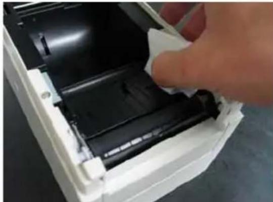
8-1. Cleaning the Paper Holder and Paper Transport
With a dry soft cloth, wipe the paper holder and paper transport to remove dust, paper particles, adhesive, and other foreign matter.
natural_image
Close-up of a hand inserting a black plastic component into a white plastic container (no text or symbols visible)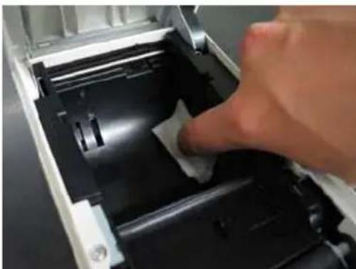
natural_image
Close-up of a hand pressing down on a mechanical component with a paper clip (no visible text or symbols)8-2. Cleaning the Platen Roller
The cleaning procedure is as follows.
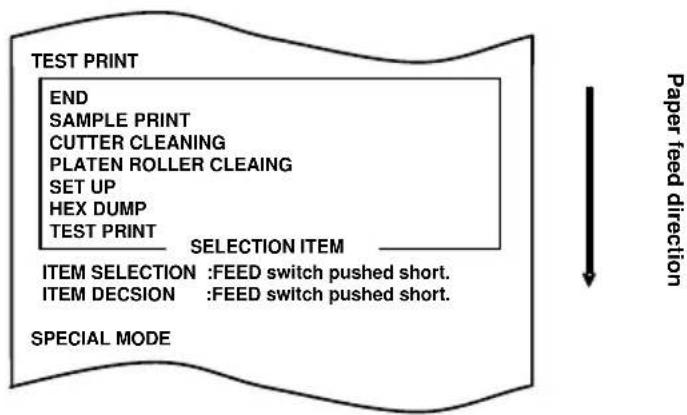
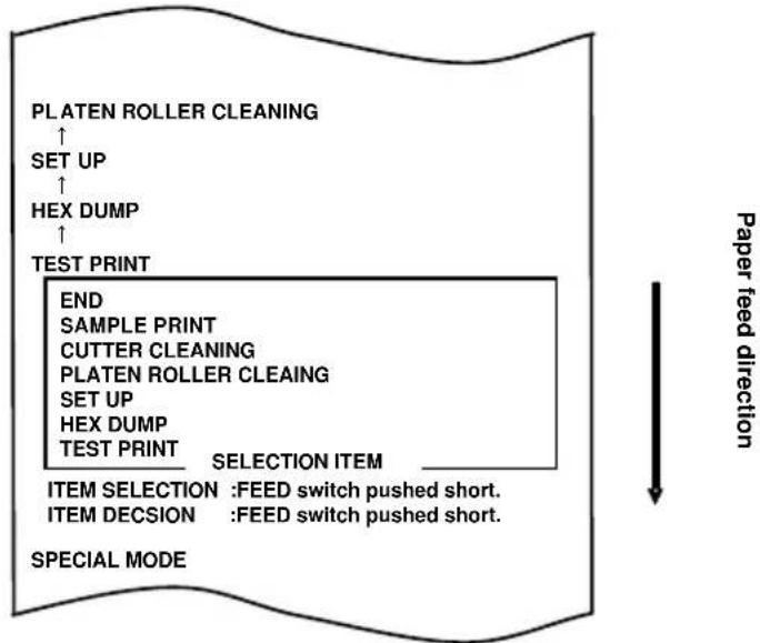
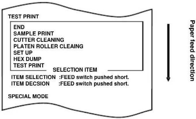
(1) With paper inserted in the printer, turn off the printer power switch once, and turn on the switch again while holding down the FEED switch on the control panel. Then, the data shown below is printed.
flowchart
graph TD
    A["END"] --> B["SAMPLE PRINT"]
    B --> C["CUTTER CLEANING"]
    C --> D["PLATEN ROLLER CLEAING"]
    D --> E["SET UP"]
    E --> F["HEX DUMP"]
    F --> G["TEST PRINT"]
    G --> H["SELECTION ITEM"]
    H --> I["ITEM SELECTION : FEED switch pushed short."]
    H --> J["ITEM DECISION : FEED switch pushed short."]
    I --> K["SPECIAL MODE"]
    J --> K
    style A fill:#f9f,stroke:#333
    style K fill:#ccf,stroke:#333
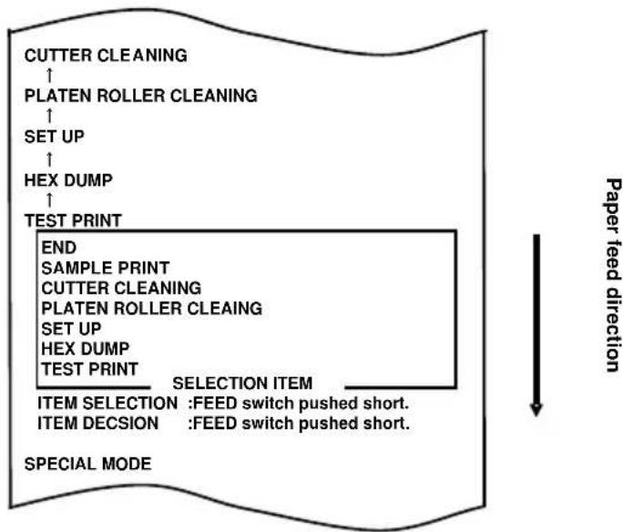
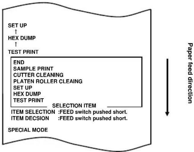
(2) Press the FEED switch briefly (one second or less) three times to move to "PLATEN ROLLER CLEANING."
flowchart
graph TD
    A["PLATEN ROLLER CLEANING"] --> B["SET UP"]
    B --> C["HEX DUMP"]
    C --> D["TEST PRINT"]
    D --> E["END"]
    E --> F["SAMPLE PRINT"]
    F --> G["CUTTER CLEANING"]
    G --> H["PLATEN ROLLER CLEANING"]
    H --> I["SET UP"]
    I --> J["HEX DUMP"]
    J --> K["TEST PRINT"]
    K --> L["SELECTION ITEM"]
    L --> M["ITEM SELECTION : FEED switch pushed short."]
    L --> N["ITEM DECISION : FEED switch pushed short."]
    O["SPECIAL MODE"] --> P["Paper feed direction"]
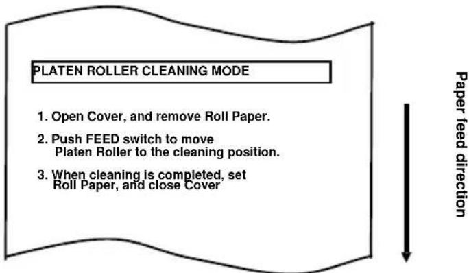
Then, press and hold down the FEED switch for one second or longer to accept the selection. The printer enters platen roller cleaning mode. The printer prints the following and cuts the paper when it enters platen roller cleaning mode:
flowchart
graph TD
    A["PLATEN ROLLER CLEANING MODE"] --> B["1. Open Cover, and remove Roll Paper."]
    B --> C["2. Push FEED switch to move Platen Roller to the cleaning position."]
    C --> D["3. When cleaning is completed, set Roll Paper, and close Cover"]
    D --> E["Paper feed direction"]
(3) Open the top cover, and remove the roll paper.
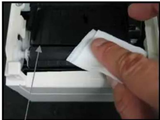
(4) Press the FEED switch to rotate the platen roller to a position that will facilitate cleaning, and then wipe the platen roller with a dry soft cloth to remove paper particles, adhesive, and other foreign matter from the surface of the platen roller.
natural_image
Close-up of a hand pressing down on a white plastic component with a paper clip (no visible text or symbols)Platen roller
(5) After completing cleaning, reposition the roll paper, and close the top cover.
Note : Take care not to dent or otherwise damage the platen roller.
A dent on the platen roller may result in incomplete printing or line feed errors.
Note : Each time that the FEED switch is pressed, the platen roller is rotated by 1/12 of a turn.
8-3. Cleaning the Thermal Head
(1) Before attempting to clean the thermal head, be sure to turn off the printer power switch.
(2) Open the top cover.
(3) Using an alcohol solvent, remove black paper particles and other residue from the surface of the thermal head. If the printer printed on label paper, any adhesive matter adhering to the surface of the thermal head must be removed.
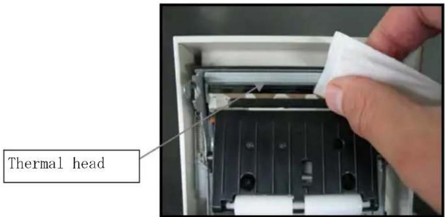
Note : The thermal head is susceptible to damage. When cleaning it, use a soft cloth and be especially careful not to damage the head.
Note: Immediately after printing, the thermal head is hot. Before cleaning the head, allow the head enough time to cool.
Note : Because the thermal head is susceptible to damage by static electricity, take precautions to prevent the generation of static electricity.
Note: Do not turn on the printer until all alcohol has dried.
Note: Do not use a solvent other than ethyl or isopropyl alcohol.
8-4. Cleaning the Cutter Blade and Frame
If the printer printed on full-sheet label paper, any adhesive matter adhering to the cutter blade and frame must be removed.
Even when label paper has been cut normally, clean the cutter blade at an interval of about once a month to ensure stability in cutting.
Note: Although the edge of the cutter blade is not as sharp as the edges of utility knives generally used in offices, there is a risk of injury to a hand or finger that is moved while pressed against the cutter blade edge. Take care to avoid injury when cleaning the cutter blade.
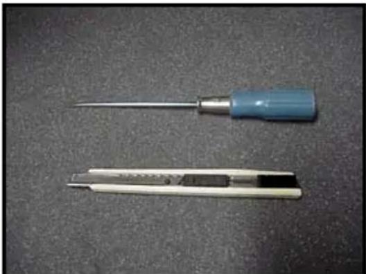
Items required for cleaning
- Flathead screwdriver (small) Cleaning sheet
- General-purpose utility knife (Product No.: 0631260)
natural_image
Two cleaning tools on a dark surface: a blue-handled screwdriver and a white-handled tool (no text or symbols visible)
The cleaning procedure is as follows.
(1) With paper inserted in the printer, turn off the printer power switch once, and turn on the switch again while holding down the FEED switch on the control panel. Then, the data shown below is printed.
Note: If you have passed the item that you want to select, repeatedly press the FEED switch briefly until you return to the first item.
flowchart
graph TD
    A["TEST PRINT"] --> B["END"]
    B --> C["SAMPLE PRINT"]
    C --> D["CUTTER CLEANING"]
    D --> E["PLATEN ROLLER CLEAING"]
    E --> F["SET UP"]
    F --> G["HEX DUMP"]
    G --> H["TEST PRINT"]
    H --> I["SELECTION ITEM"]
    I --> J["ITEM SELECTION : FEED switch pushed short."]
    I --> K["ITEM DECISION : FEED switch pushed short."]
    J --> L["SPECIAL MODE"]
    K --> L
    style A fill:#f9f,stroke:#333
    style L fill:#ccf,stroke:#333
(2) Press the FEED switch briefly (one second or less) four times to move to "CUTTER CLEANING."
flowchart
graph TD
    A["CUTTER CLEANING"] --> B["PLATEN ROLLER CLEANING"]
    B --> C["SET UP"]
    C --> D["HEX DUMP"]
    D --> E["TEST PRINT"]
    E --> F["END"]
    F --> G["SAMPLE PRINT"]
    G --> H["CUTTER CLEANING"]
    H --> I["PLATEN ROLLER CLEANING"]
    I --> J["SET UP"]
    J --> K["HEX DUMP"]
    K --> L["TEST PRINT"]
    L --> M["SELECTION ITEM"]
    M --> N["ITEM SELECTION : FEED switch pushed short."]
    M --> O["ITEM DECISION : FEED switch pushed short."]
    P["SPECIAL MODE"] --> Q["Paper feed direction"]
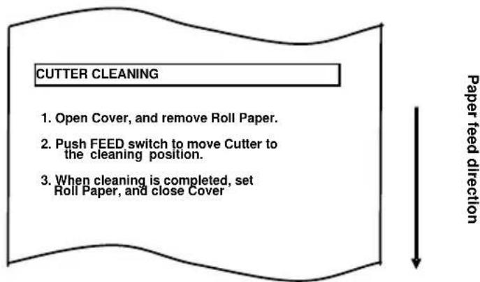
Then, press the FEED switch for one second or longer to accept the selection. The printer enters cutter cleaning mode. The printer prints the following and cuts the paper when it enters cutter cleaning mode:
flowchart
graph TD
    A["CUTTER CLEANING"] --> B["1. Open Cover, and remove Roll Paper."]
    B --> C["2. Push FEED switch to move Cutter to the cleaning position."]
    C --> D["3. When cleaning is completed, set Roll Paper, and close Cover"]
    D --> E["Downward arrow"]
(4) Press the FEED switch to move the cutter to a position that will facilitate cleaning, and then clean the cutter.
(5) After completing cleaning, reposition the roll paper, and close the top cover.
- Cleaning the Upper cutter
Using a general-purpose utility knife, flathead screwdriver, or similar tool, remove the adhesive matter adhering to the inner side and edge of the Upper cutter.
Note: Be very careful not to damage the edge of the Upper cutter when handling the utility knife or screwdriver. Also take care not to dent or otherwise damage the platen roller. A dent on the platen roller may result in incomplete printing or line feed errors.
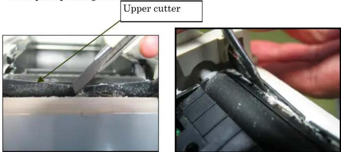
Using the cleaning sheet or a similar material, wipe off the adhesive matter adhering to the Upper cutter.
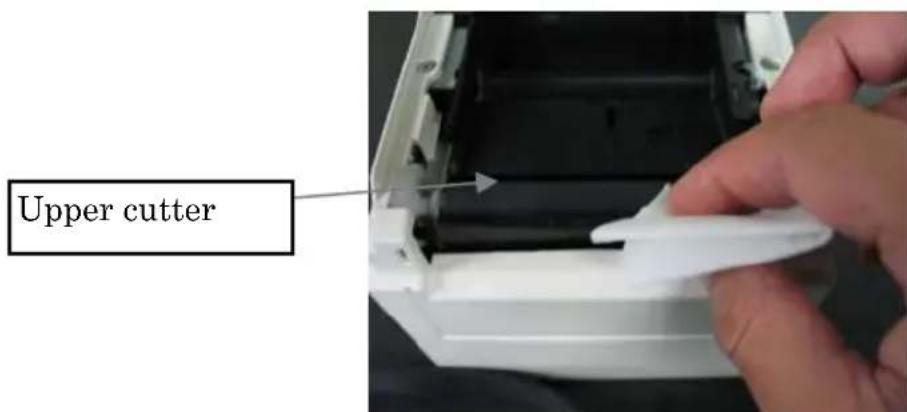
Note: Although the edge of the Upper cutter is not as sharp as the edges of the utility knives generally used in offices, there is a risk of injury to a finger that is moved while pressed directly against the edge of the cutter.
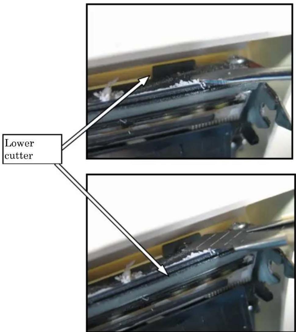
- Cleaning the Lower cutter
Using a general-purpose utility knife, flathead screwdriver, or similar tool, remove the adhesive matter adhering to the surface and edge of the Lower cutter.
Note: Be very careful not to damage the edge of the Lower cutter when handling the utility knife or screwdriver. Also take care not to dent or otherwise damage the platen roller. A dent on the platen roller may result in incomplete printing or line feed errors.
Using the cleaning sheet or a similar material, wipe off the adhesive matter adhering to the Lower cutter.
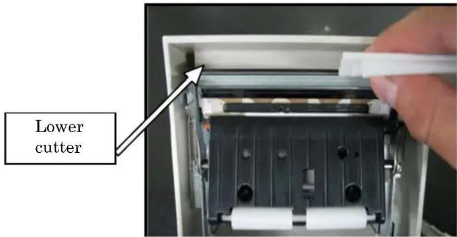
Note: Although the edge of the Lower cutter is not as sharp as the edges of utility knives generally used in offices, there is a risk of injury to a finger that is moved while pressed directly against the edge of the cutter.
(5) After completing cleaning, reposition the roll paper, and close the Top cover.
Note: Be careful when the printer is in cutter cleaning mode, because the Upper cutter is exposed. After completing cleaning, reposition the roll paper, and close the Top cover.
9. Notes on Use
(1) Printing at a high rate might result in unclear printing. If this problem occurs, adjust the printing rate. Alternatively, adjust the print speed and print density so that there are no blurs.
(See "Appendix C-3 Setting Up the Printer" in Appendix C, "Special Modes.")
(2) Printing characters from a non-standard character set e.g. in a thin serif font will result in the characters appearing very faint. Use a bold sans serif font.
(3) For quality printing that is free from uneven spacing and condensed or elongated printing after paper is cut or printing is paused, resume printing following a paper feed of at least 1 mm (8 dots).
(4) If the data transfer rate is too low, serial printing may result in uneven print density (vertical white marks may appear on printouts) because of repeated printing and pausing. If priority is placed on print quality, use batch printing mode.
(See "Appendix C-3 Setting Up the Printer" in Appendix C, "Special Modes.")
(5) The upper margin can be set to 12mm or 4.5mm with a command. If the upper margin is set to 4.5mm, reverse feeding of the paper takes place before the next printing operation. The paper must therefore be removed after each printing and cutting operation. If the paper is not removed, the part connected to the roll in partial cutting could be torn off, or the part that has been cut could be folded back. Note also that the paper length used per transaction must be at least 30mm.
(6) Printing at a high print density (110% or higher) may cause blurs or uneven print density on printouts under low-temperature conditions, depending on the print pattern. If priority is placed on print quality, use a lower print speed.
(See "Appendix C-3 Setting Up the Printer" in Appendix C, "Special Modes.")
(7) Since the difference in hue between red and black or blue and black may not be noticeable when two-color thermal paper is used, be sure to confirm in advance the color of the printed characters.
(8) When roll paper with a width of 83 mm is used, characters that are too close to the (left or right) edge of the paper may not be printed because of inaccuracies in tracking. Be sure to set a margin of sufficient width.
(9) Do not switch from narrow paper to wide paper (e.g., from paper that is 58 mm wide to paper that is 80 mm wide) during operation. When narrow paper is used, the thermal head area where there is no paper comes in direct contact with the platen roller, and the resulting wear on the head may lead to a deterioration in print quality. Similarly, if the paper width is changed, the cutter blade will cut at a location that has no paper, and the resulting wear on the blade may lead to improper cuts. To switch from narrow paper to wide paper, exchange the thermal head and the cutter blade.
(10) If label paper is used, adhesive matter adhering to the cutter blade, thermal head, paper transport, or paper holder may cause a cutting error, print error, or paper transport error. Remove adhesive matter periodically (typically on a monthly basis).
(11) If paper is left inserted in the printer for a long time, the paper may become deformed and result in thin (faint) printed characters. Before starting printing in such cases, feed the paper by 20 to 30 mm.
(12) If the type of paper used is other than the recommended ones, the print quality and thermal head life are not guaranteed. In particular, if the type of thermal paper contains Na^+ , K^+ , or Cl^- , the thermal head life may be significantly shortened.
Notes on using the cutter
(1) In full cutting mode, the length of paper per transaction must be within a range of 58 to 180 mm. If a different paper length is used, the printed paper may not drop from the paper transport, thus causing a cutting error.
(2) The maximum number of successive cuts by the cutter is 30 cuts per minute (at least two seconds per cut). Using the cutter at a higher rate may cause a failure.
(3) Do not pull the paper during cutting. Doing so may cause a paper jam or another problem.
(4) Each time that a sheet of paper is cut in full cutting mode, the sheet of paper must be removed.
Notes on printing of barcodes and two-dimensional codes
(1) Barcodes that are rotated 90 degrees or aligned vertically when printed may not be readable. Verify the readability in advance.
(2) Printouts on label paper or thick paper may contain blurs, depending on humidity and other environmental conditions. Adjust the print speed and print density appropriate for the type of paper used, and verify the readability in advance.
(See "Appendix C-3 Setting Up the Printer" in Appendix C, "Special Modes.")
(3) The recognition ratio of two-dimensional codes (QR codes, PDF417, and DataMatrix) varies depending on various factors, including the module width, print density, ambient temperature, thermal roll paper type, and reader performance. Adjust the print speed and print density appropriate to printing two-dimensional codes, and verify the readability in advance.
(See "Appendix C-3 Setting Up the Printer" in Appendix C, "Special Modes.")
(4) The paper transport accuracy may be negatively affected by printing a barcode in the Upper margin at the beginning of paper transport or in the Lower margin at the end of paper transport. Verify the readability before starting printing.
Notes on using the printer through the USB interface
(1) The printer must be connected directly to the host computer.
(2) Before starting printing, turn on the power to the printer.
(3) If a printer error occurs during printing, recover the printer from the error, and then retry printing.
(4) The host computer should not be set to any of the following modes: standby, sleep, suspend, and pause.
If the host computer or printer does not work normally after the host computer returns to normal operation mode from one of the above modes, disconnect the USB cable once and then reconnect it, or turn off the printer power switch once and then turn on the switch again. If the host computer or printer cannot be restored to normal operation after the cable is reconnected or power switch is turned on again, restart the host computer.
(5) The USB hub function cannot be used when the power to the printer is off.
(6) If a peripheral device connected to the USB hub is not recognized, perform one of the following operations:
- Disconnect the USB cable from the peripheral device once, and then reconnect it.
- Connect the peripheral device to the other port of the USB hub.
(7) The operation of connected USB devices is not guaranteed. Before using a USB device, verify its operation yourself.
Note: Do not turn off the power to the printer during printing.
If you inadvertently turn off the power to the printer during printing and the printer then fails to work normally, restart the host computer.
Note on installation
(1) The printer must be used indoors. If used outdoors, the printer may fail because of dust.
Note on the modular connector
(1) This product uses a modular connector as a dedicated connector for the cash drawer or customer display terminal. The connector must not be connected with a connector that leads to a public switched line or other such destination.
Note on using the printer in special mode
(1) If a large diameter roll is used, paper may fold or unusual noises may be heard. To prevent these problems, use a roll with a small diameter ( 50mm or less). If a Windows PC is used as the host system, a utility program can be used to make settings.
Windows® is a registered trademark of Microsoft Corporation in the United States and/or other countries.
Appendix A: Specifications
A-1.General Specifications
(1) Print method: Direct line thermal printing system
(2) Maximum print speed: 300mm/s (single-color thermal paper)
115mm/s (two color thermal paper)
(3) Dot resolution: 8 dots/mm (0.125mm)
(4) Relationship between number of print columns and character size
Body Face
| For paper 58mm wide For paper 60mm wide | |||
| 32 column printing 35 | column printing 36 | column printing | |
| ANK: Font A 32 | columns: 12x24 35 columns: 12x24 36 columns: 12x24 | ||
| ANK: Font B | 38 columns: 10x2442 columns: 9x24 | 42 columns: 10x2446 columns: 9x24 | 43 columns: 10x2448 columns: 9x24 |
| ANK: Font C 48 | columns: 8x16 52 columns: 8x16 54 columns: 8x16 | ||
| Kanji: Font A 16 | columns: 24x24 17 columns: 24x24 18 columns: 24x24 | ||
| Kanji: Font B 19 | columns: 20x24 21 columns: 20x24 21 columns: 20x24 | ||
| Kanji: Font C 24 | columns: 16x16 26 columns: 16x16 27 columns: 16x16 | ||
| ANK: Font A Extension Font | 32 columns: 12x24 35 columns: 12x24 36 columns: 12x24 | ||
| ANK: Font B Extension Font | 38 columns: 10x2442 columns: 9x24 | 42 columns: 10x2446 columns: 9x24 | 43 columns: 10x2448 columns: 9x24 |
Body Face
| For paper 80mm wide For paper 83mm wide | |||
| 42 column printing 48 | column printing 53 | column printing | |
| ANK: Font A 42 | columns: 12x24 48 columns: 12x24 53 columns: 12x24 | ||
| ANK: Font B | 51 columns: 10x2456 columns: 9x24 | 57 columns: 10x2464 columns: 9x24 | 64 columns: 10x2471 columns: 9x24 |
| ANK: Font C 64 | columns: 8x16 72 columns: 8x16 80 columns: 8x16 | ||
| Kanji: Font A 21 | columns: 24x24 24 columns: 24x24 26 columns: 24x24 | ||
| Kanji: Font B 25 | columns: 20x24 28 columns: 20x24 32 columns: 20x24 | ||
| Kanji: Font C 32 | columns: 16x16 36 columns: 16x16 40 columns: 16x16 | ||
| ANK: Font A Extension Font | 42 columns: 12x24 48 columns: 12x24 53 columns: 12x24 | ||
| ANK: Font B Extension Font | 51 columns: 10x2456 columns: 9x24 | 57 columns: 10x2464 columns: 9x24 | 64 columns: 10x2471 columns: 9x24 |
(5) Alphanumeric characters (95), extended graphics (128 x 20 pages), international characters (48)
Kanji JIS-1990 (6879), special characters (845)
(6) Dimensions of fonts
| Body Face Letter Face | ||||
| (W)x(H) dot (W)x(H) mm (W)x(H) dot (W)x(H) mm | ||||
| ANK: Font A 12 x 24 1.5 x 3.0 11 x 22 1.375 x 2.75 | ||||
| ANK: Font B | 10 x 249 x 24 | 1.25 x 3.01.125 x 3.0 | 9 x 179 x 17 | 1.125 x 2.1251.125 x 2.125 |
| ANK: Font C 8 x 16 1.0 x 2.0 8 x 13 1.0 x 1.625 | ||||
| Kanji: Font A 24 x 24 3.0 x 3.0 24 x 24 3.0 x 3.0 | ||||
| Kanji: Font B 20 x 24 2.5 x 3.0 18 x 24 2.25 x 3.0 | ||||
| Kanji: Font C 16 x 16 2.0 x 2.0 15 x 15 1.875 x 1.875 | ||||
| ANK: Font A Extension Font | 12 x 24 1.5 x 3.0 12 x 24 1.5 x 3.0 | |||
| ANK: Font B Extension Font | 10 x 249 x 24 | 1.25 x 3.01.125 x 3.0 | 9 x 229 x 22 | 1.125 x 2.751.125 x 2.75 |
(7) Outline drawing
A-2.Cutter Specifications
Cutting method: Partial cutting model
The paper remains connected at one point Partial/full cutting model
A command for switching between partial cutting and full cutting is provided for models that support these two cutting methods.
Note : For printing on label paper, use only partial cutting. If full cutting is used in such cases, paper cutting performance will deteriorate faster because of the greater adverse effect of adhesive matter.
Note : Paper cutting performance may deteriorate faster with the use of label paper because of its adhesive matter. Clean the cutter blade periodically to remove the adhesive matter.
Note : Full cutting may lead to irregularities at the center of the cutting surface. If paper fiber remains at these locations, this may eventually lead to incomplete cutting at these locations.
Note : In full cutting mode, the printed paper must be removed each time that one sheet is printed. Otherwise, printed paper remains in the automatic cutter section and may cause a cutting error.
Note : The maximum number of successive cuts by the cutter is 30 cuts per minute (at least two seconds per cut). Using the cutter at a higher rate may cause a failure.
A-3. Paper Supply Specifications
(1) Loading method: Rolls are loaded manually.
(2) Paper near end: Detected when only a little paper is left.
Note: This printer supports paper rolls with a core diameter of 18mm.
A-4. Interface Specifications
(1) Parallel (Complies with IEEE1284: Nibble mode)
(2) Dual (Conforms to USB 1.1 and RS-232C)
(3) LAN (10BASE-T, 100BASE-TX)
A-5.Environment Specifications
(1) Temperature
When operating : Operation guaranteed from 0° C to 40°C.
Printing guaranteed from 5°C to 35°C.
When no operating : -5°C to 60°C
When being transported or stored : -20°C to 60°C
(While packaged)
(2) Humidity
When operating : Operation guaranteed from 10% to 95%RH
(no condensation)
Printing guaranteed from 10% to 85%RH
(no condensation)
When no operating : 8% to 95% RH (no condensation)
When being transported or stored : 5% to 95% RH
(While packaged) (no condensation)
(3) Maximum wet bulb temperature : 29°C or less
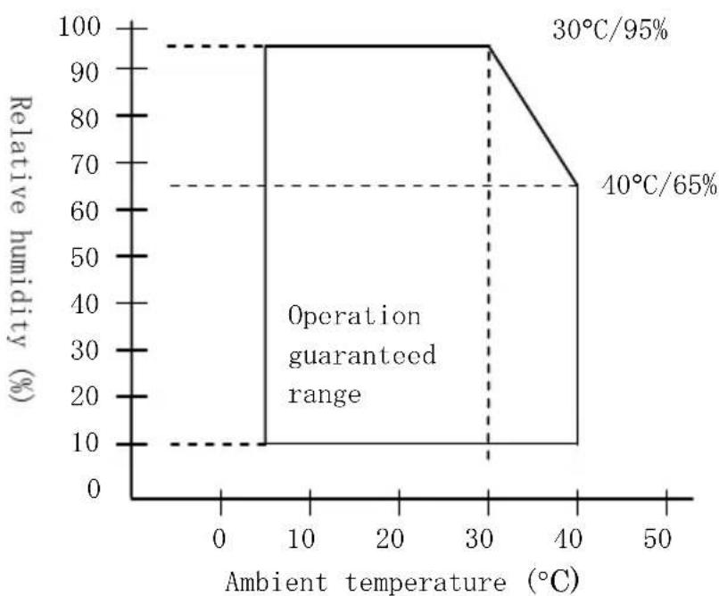
line
| Ambient temperature (°C) | Relative humidity (%) | | ------------------------ | --------------------- | | 0 | 10 | | 30 | 100 | | 40 | 65 | | 50 | 65 |A-6. Specifications of Reliability
(1) Printer life
Feed of 25 million lines (Specified thermal paper) or 5 years
(2) Head
Running life : 150km (Specified single-color thermal paper)
75km (Specified dual-color thermal paper)
Pulse life : 150 million pulses
(3) Cutter
- Partial cutting model
2,000,000 cuts (Specified thermal paper 75μm)
500,000 cuts (Specified thick thermal paper 150μm)
300,000 cuts (Specified label thermal paper)
- Partial/full cutting model
With only partial cutting used:
2,000,000 cuts (for paper with a specified thickness of 75 m)
500,000 cuts (for paper with a specified thickness of 75 to 150 m )
300,000 cuts (for the specified full-sheet label paper)
With only full cutting used:
1,000,000 cuts (for paper with a specified thickness of 75 m)
500,000 cuts (for paper with a specified thickness of 75 to 150 m )
* If both partial cutting and full cutting are used, the cutter life is different from the above and depends on the conditions of use.
Note : Paper cutting performance may deteriorate faster with the use of label paper because its adhesive matter adheres to the cutter blade. Clean the cutter blade periodically.
Appendix B: Interface
B-1.Parallel Interface
(1) Forward channel
| Pin No. | Signal name I/O | direction | Pin No. | Signal name I/O | direction | |
| 1 | *STROBE | Input | 19 | *STROBE-RET | --- | |
| 2 | DATA1 | Input | 20 | DATA1-RET | --- | |
| 3 | DATA2 | Input | 21 | DATA2-RET | --- | |
| 4 | DATA3 | Input | 22 | DATA3-RET | --- | |
| 5 | DATA4 | Input | 23 | DATA4-RET | --- | |
| 6 | DATA5 | Input | 24 | DATA5-RET | --- | |
| 7 | DATA6 | Input | 25 | DATA6-RET | --- | |
| 8 | DATA7 | Input | 26 | DATA7-RET | --- | |
| 9 | DATA8 | Input | 27 | DATA8-RET | --- | |
| 10 | *ACKNLG | Output | 28 | *ACKNLG-RET | --- | |
| 11 | BUSY | Output | 29 | BUSY-RET | --- | |
| 12 | PE | Output | 30 | *INIT-RET | --- | |
| 13 | SLCT | Output | 31 | *INIT | Input | |
| 14 | *AUTOFEEDXT Input | 32 | *FAULT | Output | ||
| 15 | N.C. | --- | 33 | SG1 | Output | |
| 16 | SG1 | --- | 34 | DK_STATUS | Output | |
| 17 | FG | --- | 35 | +5V | Output | |
| 18 | LOGIC-H | Output | 36 | *SLCTIN | Input | |
Notes 1: Each -RET is connected to SG.
Notes 2: "*" indicates a negative-logic signal.
(2) Reverse channel
| Pin No. | Signal name I/O | Pin No. | Signal name I/O | ||
| direction | direction | ||||
| 1 | HostClk | Input | 19 | HostClk-RET | --- |
| 2 | DATA1 | Input | 20 | DATA1-RET | --- |
| 3 | DATA2 | Input | 21 | DATA2-RET | --- |
| 4 | DATA3 | Input | 22 | DATA3-RET | --- |
| 5 | DATA4 | Input | 23 | DATA4-RET | --- |
| 6 | DATA5 | Input | 24 | DATA5-RET | --- |
| 7 | DATA6 | Input | 25 | DATA6-RET | --- |
| 8 | DATA7 | Input | 26 | DATA7-RET | --- |
| 9 | DATA8 | Input | 27 | DATA8-RET | --- |
| 10 | PtrClk | Output | 28 | PtrClk-RET | --- |
| 11 | PtrBusy | Output | 29 | PtrBusy-RET | --- |
| 12 | AckDateReq | Output | 30 | *INIT-RET | --- |
| 13 | Xflag | Output | 31 | *INIT | Input |
| 14 | HostBusy | Input | 32 | *DataAvail | Output |
| 15 | N.C. | --- | 33 | SG1 | Output |
| 16 | SG1 | --- | 34 | DK_STATUS | Output |
| 17 | FG | --- | 35 | +5V | Output |
| 18 | LOGIC-H | Output | 36 | 1284-Active | Input |
Notes 1: Each -RET is connected to SG.
Notes 2: "*" indicates a negative-logic signal.
B-2.Dual Interface
(1) Type B Connector: 4 Pin
| Pin No. | Signal name I/O | direction Signal | line name |
| 1 | VBUS | Input | +5V |
| 2 | D-inB | Input/Output | D- |
| 3 | D+inB | Input/Output | D+ |
| 4 | SG1 | --- | Ground |
(2) Serial interface connector
| Pin No. | Signal name I/O | direction Function | |
| 1 | FG | --- Frame ground | |
| 2 | TXD | Output | Send data |
| 3 | RXD | Input | Receive data |
| 4 | RTS | Output | Send request |
| 5 | CTS | Input | Send permission |
| 6 | DSR | Input | Data set ready |
| 7 | SG | --- Signal ground | |
| 8 to 19 | N.C. | --- | Unused |
| 20 | DTR | Output | Data terminal ready |
| 21 to 24 | N.C. | --- | Unused |
| 25 | INIT | Input | Forced reset |
Notes 1: Use inch- screws to secure the connection.
Notes 2: Shielded USB cables must be used.
B-3.LAN Interface
(1) LAN Connector TCP/IP (10BASE-T/100BASE-TX1 Port)
Note 1: Please refer the manual with IP address setting utility for how to set IP address.
Note 2: You can find the MAC address in the side of LAN Connector.
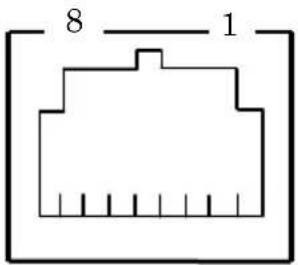
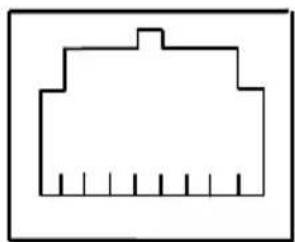
(2) Connector: 8Pins RJ-45 (Printer Side)
| No. | Signal Input / | Output Reference | ||
| 1 | TX+ | Output | Output | Data |
| 2 | TX- | Output | Output | Data |
| 3 | RX+ | Input | Input | Data |
| 4 | N.C | - | ||
| 5 | N.C | - | ||
| 6 | RX- | Input | Input | Data |
| 7 | N.C | - | ||
| 8 | N.C | - | ||
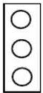
(3) LED
| No. | Display | Action contents |
| 3 | Status When receives packet, lights up for 50msec. | |
| 2 | 100BASE-TX Link | When the connection is recognized as 100BASE-TX, lights up. |
| 1 | 10BASE-T Link When the connection is recognized as 10BASE-T, lights up. | |
natural_image
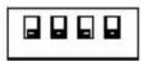
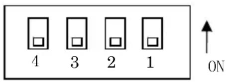
Simple line drawing of a building outline with vertical supports (no text or symbols)(4) DIP Switch
Note 1: This switch is maintenance use. Please use all switches by OFF setting.
| No. | ON | OFF | |
| 1 | - | Off | |
| 2 | Settings | Initialization | - |
| 3 | Settings | Information | - |
| 4 Self Test for LAN Board - | |||
Initialization of settings
1) Turn off the printer.
2) Set the DIP Switch No.2 "ON".
3) Turn on the printer, and wait approximately 5 seconds until completion of initialization.
4) Turn off the printer again.
5) Set the DIP Switch No.2 "OFF".
Self test print of settings
1) Turn off the printer.
2) Set the DIP Switch No.3 and No.4 "ON".
3) Turn on the printer, and Printer prints Self test.
4) Turn off the printer again.
5) Set the DIP Switch No.3 and No.4 "OFF".
Note: Be careful of handling DIP Switches.
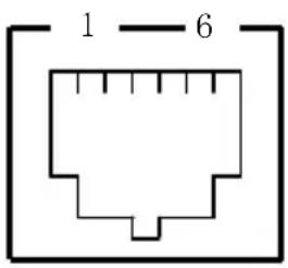
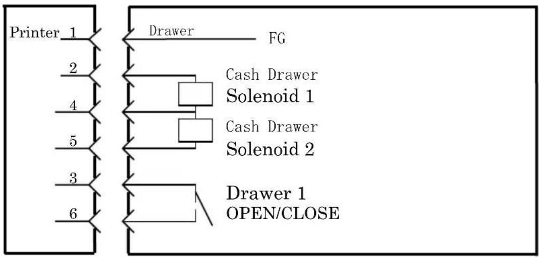
B-4. Drawer Kick Connector
| Pin No. | Signal name I/O | direction Signal | line name |
| 1 FG | Output | Drawer frame ground | signal |
| 2 *DRD1 | Output | Drawer kick drive | signal 1 |
| 3 DRSNS1 | Input | Drawer sense signal | 1 |
| 4 | +24V | Output | Drive power |
| 5 *DRD2 | Output | Drawer kick drive | signal 2 |
| 6 SG | Output | Drawer sense ground | signal |
Notes 1: "*" indicates a negative-logic signal.
Connecting side
flowchart
graph TD
    A["Printer 1"] --> B["Drawer FG"]
    C["Printer 2"] --> D["Cash Drawer Solenoid 1"]
    E["Printer 4"] --> F["Cash Drawer Solenoid 2"]
    G["Printer 5"] --> H["Drawer 1 OPEN/CLOSE"]
    I["Printer 3"] --> J["Drawer 1 OPEN/CLOSE"]
    K["Printer 6"] --> L["Drawer 1 OPEN/CLOSE"]
Notes : Use a shielded drawer cable.
Notes : Two drives cannot be driven simultaneously.
Notes :The drawer on/off time must be specified using t1 and t2 in the pulse generation command (ESC p m t1 t2).
Notes: The drawer drive duty must be as follows:
$$ \text {ON - time / (ON - time + OFF - time)} \leq 0. 2 $$
Notes :The drawer power must always be supplied from the printer power supply unit via connector pin 4.
Notes :The resistance of the drawer kick solenoid must be at least 24Ω. If a solenoid with a lower resistance is used, the solenoid might be destroyed by over current.
Notes :This product uses a modular connector as a dedicated connector for the cash drawer or customer display terminal. The connector must not be connected with a connector that leads to a public switched line or other such destination.
B-5. Specifications of Power Supply
(1) Operating voltage : DC 24V±10%
(2) Current consumption :- Standby: 4.5W or less/0.2A on average
Note: Maximum drawer kick drive current: 1A Two drawer kicks must not be driven simultaneously.
- Average current consumption Operating: About 44W/1.5A on average (at 24V, 25°C, print density setting 100%, paper width 80mm, print duty 9%)
Arrangement of power connector pins
| Pin No. | Signal name |
| 1 | +24 |
| 2 | SG |
| 3 | N.C |

Note : Use our AC adapter to supply power.
Note : If our AC adapter is not used (power supply is supplied by the user), problems such as bad print quality, electromagnetic interference, or circuit noise may occur. In such cases, take note of the following points:
- Use an AC adapter whose capacity corresponds to the printing rate that will actually be used.
- Ensure in advance that there are no problems such as static electricity, electromagnetic interference, circuit noise, etc.
Appendix C: Special Modes
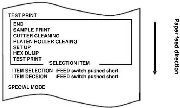
C-1.Test Printing
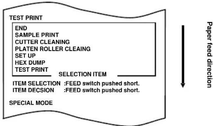
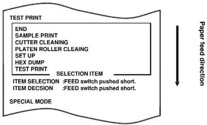
With paper inserted in the printer, turn off the printer power switch once, and turn on the switch again while holding down the FEED switch on the control panel. Then, the data shown below is printed. When "TEST PRINT" is printed, press and hold down the FEED switch for one second or longer to start test printing.
After printing a certain amount of data, the printer automatically cuts the paper and ends the test printing. To terminate test printing in progress, press the FEED switch. Then, the printer cuts the paper and terminates the test printing.
Test printing
flowchart
graph TD
    A["TEST PRINT"] --> B["END"]
    B --> C["SAMPLE PRINT"]
    C --> D["CUTTER CLEANING"]
    D --> E["PLATEN ROLLER CLEAING"]
    E --> F["SET UP"]
    F --> G["HEX DUMP"]
    G --> H["TEST PRINT"]
    H --> I["SELECTION ITEM"]
    I --> J["ITEM SELECTION : FEED switch pushed short."]
    I --> K["ITEM DECISION : FEED switch pushed short."]
    L["SPECIAL MODE"] --> M["--> Paper feed direction"]
Sample test printout
PT390 Ver*.*
123456
POWER ON STATUS ENABLE
RECEIVE BUFFER 4K BYTE
BUSY CONDITION BUFFERFULL
RECEIVE ERROR ?PRINT
AUTO LF DISABLE
DSR(#6) RESET DISABLE
:
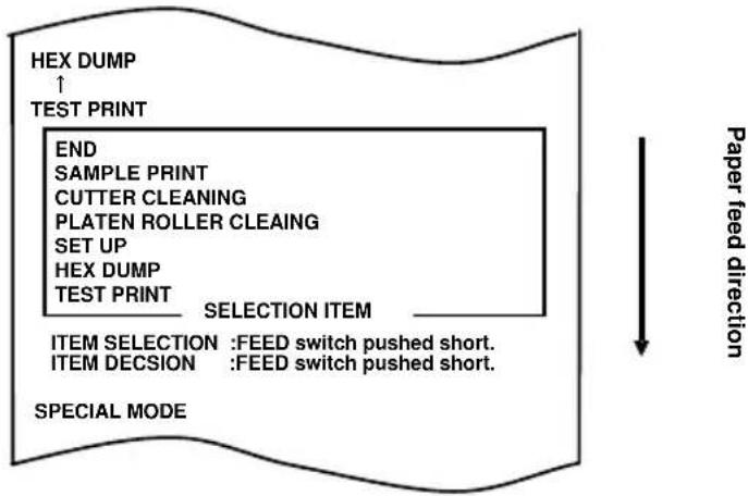
C-2.Hex Dump
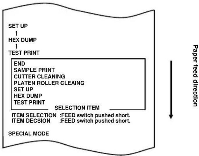
With paper inserted in the printer, turn off the printer power switch once. If you turn on the switch again while holding down the FEED switch on the control panel, the data shown in Section C-1 will be printed. If you turn on the switch again and press the FEED switch briefly, the data shown below will be printed.
flowchart
graph TD
    A["EXX DUMP ↑ TEST PRINT"] --> B["END SAMPLE PRINT CUTTER CLEANING PLATEN ROLLER CLEAING SET UP HEX DUMP TEST PRINT SELECTION ITEM"]
    B --> C["ITEM SELECTION : FEED switch pushed short. ITEM DECISION : FEED switch pushed short."]
    C --> D["SPECIAL MODE"]
    style A fill:#f9f,stroke:#333
    style D fill:#ccf,stroke:#333
When "HEX DUMP" is printed, press and hold down the FEED switch for one second or longer to place the printer in hex dump mode.
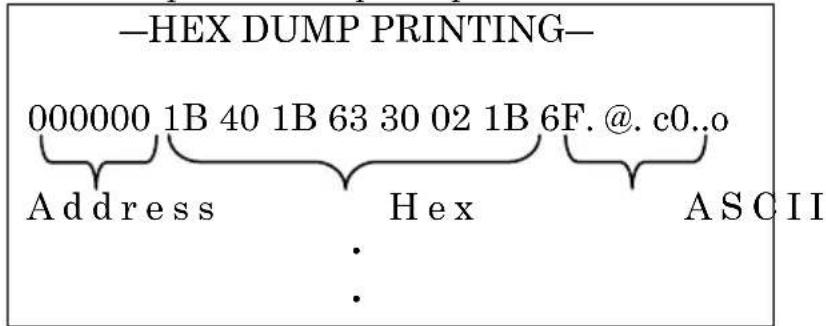
In hex dump mode, all signals sent from the host computer to the printer are printed as hexadecimal codes. The printed data can be used to confirm that the correct control codes have been sent to the printer by a created program. To reset this mode, turn off the power switch once.
Sample hex dump test printout
C-3. Setting Up the Printer
This section explains how to set up the printer without using a PC.
With the printer connected to a Windows PC, you can easily change the settings by using the setup tool contained on the CD-ROM provided with the printer.
For the procedure of installation of the utility, see the "Chapter 3. Installation" in the "Installation Guide" (\Manuals\PT390_InstallGuide1_en.pdf).
Example (1): Changing the print density to a higher value
Change from 100% to 130%
The procedure for this setting is as follows.
- Before starting work for this setting, verify the following conditions of the printer:
(1) The power is off.
(2) Roll paper is inserted in it.
(3) The cover is closed.
- Enter special mode.
Turn on the power switch on the right side of the printer while holding down the FEED switch on the left part of the Top cover.
The printer prints the following when it enters special mode:
flowchart
graph TD
    A["END"] --> B["SAMPLE PRINT"]
    B --> C["CUTTER CLEANING"]
    C --> D["PLATEN ROLLER CLEAING"]
    D --> E["SET UP"]
    E --> F["HEX DUMP"]
    F --> G["TEST PRINT"]
    G --> H["SELECTION ITEM"]
    H --> I["ITEM SELECTION : FEED switch pushed short."]
    H --> J["ITEM DECISION : FEED switch pushed short."]
    I --> K["SPECIAL MODE"]
    J --> K
    style A fill:#f9f,stroke:#333
    style K fill:#ccf,stroke:#333
- Enter setup mode from special mode.
Press the FEED switch briefly (one second or less) twice to move to "SET UP."
flowchart
graph TD
    A["SET UP"] --> B["HEX DUMP"]
    B --> C["TEST PRINT"]
    C --> D["END"]
    D --> E["SAMPLE PRINT"]
    E --> F["CUTTER CLEANING"]
    F --> G["PLATEN ROLLER CLEAING"]
    G --> H["SET UP"]
    H --> I["HEX DUMP"]
    I --> J["TEST PRINT"]
    J --> K["SELECTION ITEM"]
    K --> L["ITEM SELECTION : FEED switch pushed short."]
    L --> M["ITEM DECISION : FEED switch pushed short."]
    M --> N["SPECIAL MODE"]
    style A fill:#f9f,stroke:#333
    style N fill:#f9f,stroke:#333
Then, press and hold down the FEED switch for one second or longer to accept the selection.
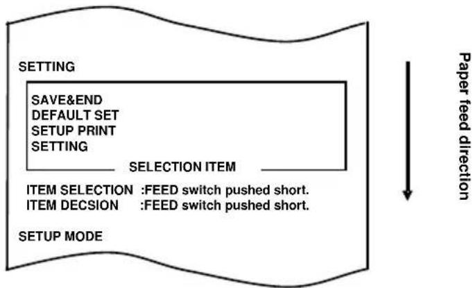
The printer prints the following when it enters setup mode:
flowchart
graph TD
    A["SETTING"] --> B["SELECTION ITEM"]
    B --> C["ITEM SELECTION : FEED switch pushed short."]
    B --> D["ITEM DECISION : FEED switch pushed short."]
    C --> E["SETUP MODE"]
    D --> E
    style A fill:#f9f,stroke:#333
    style B fill:#ccf,stroke:#333
    style C fill:#cfc,stroke:#333
    style D fill:#fcc,stroke:#333
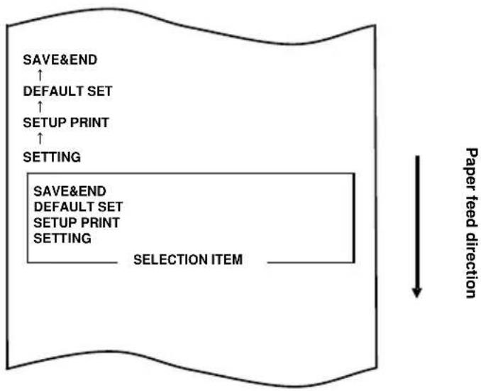
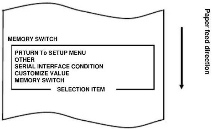
- In setup mode, select "SETTING."
Press and hold down the FEED switch for one second or longer to accept the selection.
The printer prints the following when you accept the selection of "SETTING":
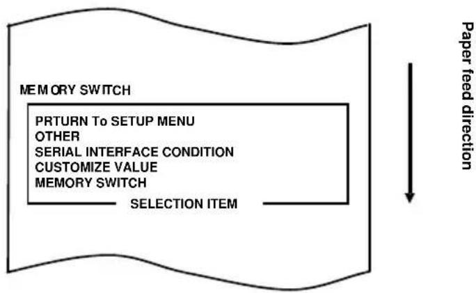
flowchart
graph TD
    A["MEMORY SWITCH"] --> B["PRETURN TO SETUP MENU"]
    B --> C["OTHER"]
    C --> D["SERIAL INTERFACE CONDITION"]
    D --> E["CUSTOMIZE VALUE"]
    E --> F["MEMORY SWITCH"]
    F --> G["SELECTION ITEM"]
    G --> H["Paper feed direction"]
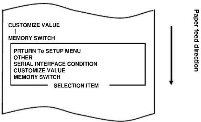
- Select "CUSTOMIZE VALUE" as your option.
Press the FEED switch briefly (one second or less) until the item "CUSTOMIZE VALUE" is reached.
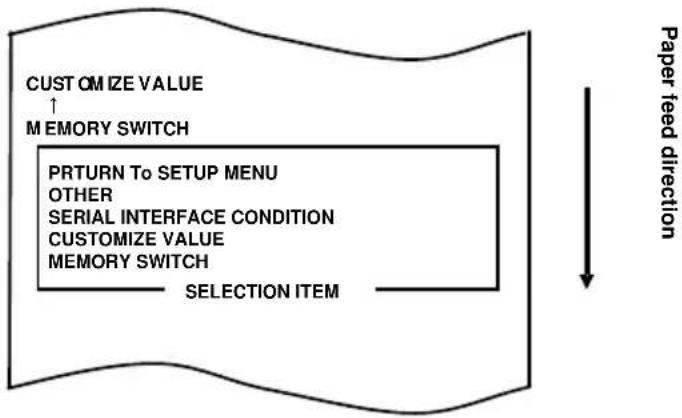
flowchart
graph TD
    A[" Papua feed direction "] --> B[" Selection Item "]
    B --> C[" MEMORY SWITCH "]
    C --> D[" CUSTOMIZE VALUE ↑"]
    D --> E[" PRTURN TO SETUP MENU OTHER SERIAL INTERFACE CONDITION CUSTOMIZE VALUE MEMORY SWITCH "]
    E --> F[" Paper feed direction "]
    style A fill:#f9f,stroke:#333
    style B fill:#ccf,stroke:#333
    style C fill:#cfc,stroke:#333
    style D fill:#fcc,stroke:#333
    style E fill:#cff,stroke:#333
    style F fill:#ffc,stroke:#333
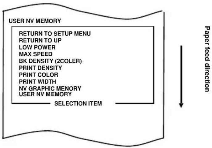
Then, press and hold down the FEED switch for one second or longer to accept the selection.
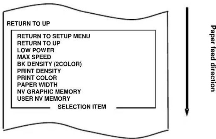
The printer prints the following when you accept the selection of "CUSTOMIZE VALUE":
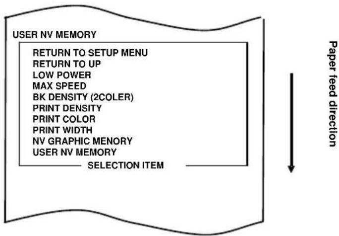
flowchart
graph TD
    A["USER NV MEMORY"] --> B["RETURN TO SETUP MENU"]
    B --> C["RETURN TO UP"]
    C --> D["LOW POWER"]
    D --> E["MAX SPEED"]
    E --> F["BK DENSITY (2COLER)"]
    F --> G["PRINT DENSITY"]
    G --> H["PRINT COLOR"]
    H --> I["PRINT WIDTH"]
    I --> J["NV GRAPHIC MEMORY"]
    J --> K["USER NV MEMORY"]
    K --> L["SELECTION ITEM"]
    L --> M["Paper feed direction"]
- Select "PRINT DENSITY" as your option.
Press the FEED switch briefly (one second or less) four times to move to "PRINT DENSITY."
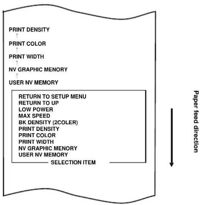
flowchart
graph TD
    A["USER NV MEMORY"] --> B["NV GRAPHIC MEMORY"]
    B --> C["PRINT WIDTH"]
    C --> D["PRINT COLOR"]
    D --> E["PRINT DENSITY"]
    E --> F["RETURN TO SETUP MENU"]
    F --> G["RETURN TO UP"]
    G --> H["LOW POWER"]
    H --> I["MAX SPEED"]
    I --> J["BK DENSITY (2COLER)"]
    J --> K["PRINT DENSITY"]
    K --> L["PRINT COLOR"]
    L --> M["PRINT WIDTH"]
    M --> N["NV GRAPHIC MEMORY"]
    N --> O["USER NV MEMORY"]
    O --> P["SELECTION ITEM"]
    style A fill:#f9f,stroke:#333
    style P fill:#ccf,stroke:#333
Then, press and hold down the FEED switch for one second or longer to accept the selection.
The printer prints the following when you accept the selection of "PRINT DENSITY":
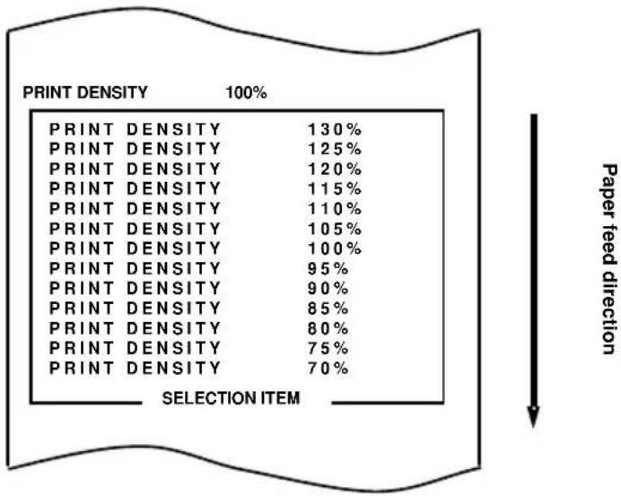
other
| PRINT DENSITY | Percentage (%) | |---|---| | PRINT DENSITY | 130 | | PRINT DENSITY | 125 | | PRINT DENSITY | 120 | | PRINT DENSITY | 115 | | PRINT DENSITY | 110 | | PRINT DENSITY | 105 | | PRINT DENSITY | 100 | | PRINT DENSITY | 95 | | PRINT DENSITY | 90 | | PRINT DENSITY | 85 | | PRINT DENSITY | 80 | | PRINT DENSITY | 75 | | PRINT DENSITY | 70 | SELECTION ITEM Paper feed direction7. Select "130%" as your option.
Press the FEED switch briefly (one second or less) until the item "130%" is reached.
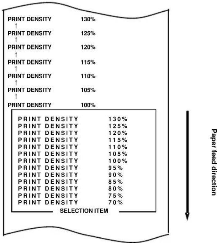
bar
| Selection Item | Percentage (%) | |---|---| | PRINT DENSITY | 130 | | PRINT DENSITY | 125 | | PRINT DENSITY | 120 | | PRINT DENSITY | 115 | | PRINT DENSITY | 110 | | PRINT DENSITY | 105 | | PRINT DENSITY | 100 | | PRINT DENSITY | 130 | | PRINT DENSITY | 125 | | PRINT DENSITY | 120 | | PRINT DENSITY | 115 | | PRINT DENSITY | 110 | | PRINT DENSITY | 105 | | PRINT DENSITY | 100 | | PRINT DENSITY | 95 | | PRINT DENSITY | 90 | | PRINT DENSITY | 85 | | PRINT DENSITY | 80 | | PRINT DENSITY | 75 | | PRINT DENSITY | 70 | Paper feed directionThen, press and hold down the FEED switch for one second or longer to accept the selection.
The printer prints the following when you accept the selection of "130%":
flowchart
graph TD
    A["RETURN TO UP"] --> B["RETURN TO SETUP MENU"]
    B --> C["RETURN TO UP"]
    C --> D["LOW POWER"]
    D --> E["MAX SPEED"]
    E --> F["BK DENSITY (2COLOR)"]
    F --> G["PRINT DENSITY"]
    G --> H["PRINT COLOR"]
    H --> I["PAPER WIDTH"]
    I --> J["NV GRAPHIC MEMORY"]
    J --> K["USER NV MEMORY"]
    K --> L["SELECTION ITEM"]
    style A fill:#f9f,stroke:#333
    style L fill:#ccf,stroke:#333
    note right of A Paper feed direction
- Select "RETURN TO UP" as your option.
Press and hold down the FEED switch for one second or longer to accept the selection.
The printer prints the following when you accept the selection of "RETURN TO UP":
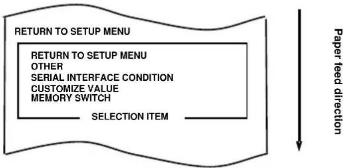
flowchart
graph TD
    A["RETURN TO SETUP MENU"] --> B["RETURN TO SETUP MENU"]
    B --> C["OTHER"]
    C --> D["SERIAL INTERFACE CONDITION"]
    D --> E["CUSTOMIZE VALUE"]
    E --> F["MEMORY SWITCH"]
    F --> G["SELECTION ITEM"]
    G --> H["Paper feed direction"]
- Select "RETURN TO SETUP MENU" as your option.
Press and hold down the FEED switch for one second or longer to accept the selection
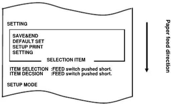
The printer prints the following when you accept the selection of "RETURN TO SETUP MENU":
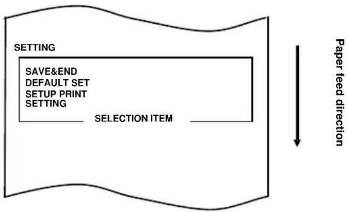
flowchart
graph TD
    A["SETTING"] --> B["SAVE&END"]
    A --> C["DEFAULT SET"]
    A --> D["SETUP PRINT"]
    A --> E["SETTING"]
    E --> F["SELECTION ITEM"]
    F --> G["Paper feed direction"]
- Select "SAVE&END" as your option.
Press the FEED switch briefly (one second or less) until the item "SAVE&END" is reached.
flowchart
graph TD
    A["SELECTED ITEMS"] --> B[" Paper feed direction "]
    B --> C[" SETTING "]
    C --> D[" SETUP PRINT "]
    D --> E[" DEFAULT SET "]
    E --> F[" SAVE&END "]
    F --> G[" Percentage"]
    style A fill:#f9f,stroke:#333
    style B fill:#ccf,stroke:#333
    style C fill:#cfc,stroke:#333
    style D fill:#fcc,stroke:#333
    style E fill:#cff,stroke:#333
    style F fill:#ffc,stroke:#333
    style G fill:#fcc,stroke:#333
Then, press and hold down the FEED switch for one second or longer to accept the selection.
The printer cuts the paper and exits from setup mode when you accept the selection of "SAVE&END."
Note: If you turn off the printer power switch without first selecting "SAVE&END," your setting will be lost.
- Verifying your setting
To verify your setting, execute a test print, referring to Section C-1. The test printing prints a list of printer settings. Check the list, and verify your setting.
Example (2): Changing the print speed to a lower value
Change from 11 (Max. 300 mm/s) to 5 (Max. 180 mm/s)
The procedure for this setting is as follows.
- Before starting work for this setting, verify the following conditions of the printer:
(1) The power is off.
(2) Roll paper is inserted in it.
(3) The cover is closed.
- Enter special mode.
Turn on the power switch on the right side of the printer while holding down the FEED switch on the left part of the Top cover.
The printer prints the following when it enters special mode:
flowchart
graph TD
    A["END"] --> B["SAMPLE PRINT"]
    B --> C["CUTTER CLEANING"]
    C --> D["PLATEN ROLLER CLEAING"]
    D --> E["SET UP"]
    E --> F["HEX DUMP"]
    F --> G["TEST PRINT"]
    G --> H["SELECTION ITEM"]
    H --> I["ITEM SELECTION : FEED switch pushed short."]
    H --> J["ITEM DECISION : FEED switch pushed short."]
    I --> K["SPECIAL MODE"]
    J --> K
    style A fill:#f9f,stroke:#333
    style K fill:#ccf,stroke:#333
- Enter setup mode from special mode.
Press the FEED switch briefly (one second or less) twice to move to "SET UP."
flowchart
graph TD
    A["SET UP"] --> B["HEX DUMP"]
    B --> C["TEST PRINT"]
    C --> D["END"]
    D --> E["SAMPLE PRINT"]
    E --> F["CUTTER CLEANING"]
    F --> G["PLATEN ROLLER CLEAING"]
    G --> H["SET UP"]
    H --> I["HEX DUMP"]
    I --> J["TEST PRINT"]
    J --> K["SELECTION ITEM"]
    K --> L["ITEM SELECTION : FEED switch pushed short."]
    K --> M["ITEM DECISION : FEED switch pushed short."]
    N["SPECIAL MODE"] --> O["Paper feed direction"]
Then, press and hold down the FEED switch for one second or longer to accept the selection.
The printer prints the following when it enters setup mode:
flowchart
graph TD
    A["SETTING"] --> B["SAVE&END"]
    B --> C["DEFAULT SET"]
    C --> D["SETUP PRINT"]
    D --> E["SETTING"]
    E --> F["SELECTION ITEM"]
    F --> G["ITEM SELECTION : FEED switch pushed short."]
    G --> H["ITEM DECISION : FEED switch pushed short."]
    H --> I["SETUP MODE"]
    I --> J["Paper feed direction"]
- In setup mode, select "SETTING."
Press and hold down the FEED switch for one second or longer to accept the selection.
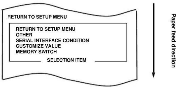
The printer prints the following when you accept the selection of "SETTING":
flowchart
graph TD
    A["MEMORY SWITCH"] --> B["PRTURN TO SETUP MENU"]
    B --> C["OTHER"]
    C --> D["SERIAL INTERFACE CONDITION"]
    D --> E["CUSTOMIZE VALUE"]
    E --> F["MEMORY SWITCH"]
    F --> G["SELECTION ITEM"]
    G --> H["Paper feed direction"]
- Select "CUSTOMIZE VALUE" as your option.
Press the FEED switch briefly (one second or less) until the item "CUSTOMIZE VALUE" is reached.
flowchart
graph TD
    A["Customize VALUE ↑ MEMORY SWITCH"] --> B["PRTURN To SETUP MENU OTHER SERIAL INTERFACE CONDITION CUSTOMIZE VALUE MEMORY SWITCH"]
    B --> C["SELECTION ITEM"]
    D["Paper feed direction"] --> E["Downward arrow"]
Then, press and hold down the FEED switch for one second or longer to accept the selection.
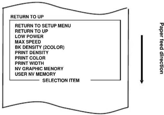
The printer prints the following when you accept the selection of "CUSTOMIZE VALUE":
flowchart
graph TD
    A["USER NV MEMORY"] --> B["RETURN TO SETUP MENU"]
    B --> C["RETURN TO UP"]
    C --> D["LOW POWER"]
    D --> E["MAX SPEED"]
    E --> F["BK DENSITY (2COLER)"]
    F --> G["PRINT DENSITY"]
    G --> H["PRINT COLOR"]
    H --> I["PRINT WIDTH"]
    I --> J["NV GRAPHIC MEMORY"]
    J --> K["USER NV MEMORY"]
    K --> L["SELECTION ITEM"]
    L --> M["Paper feed direction"]
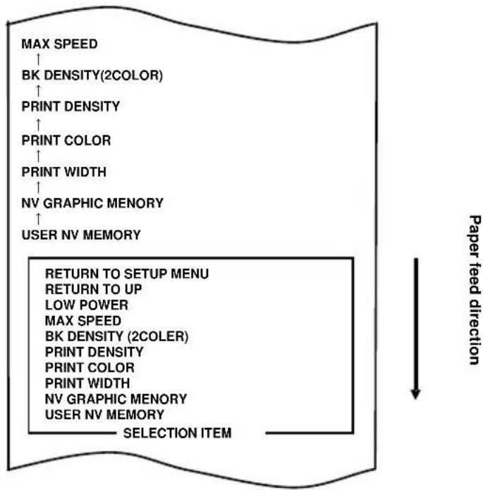
- Select "MAX SPEED" as your option.
Press the FEED switch briefly (one second or less) six times to move to "MAX SPEED."
flowchart
graph TD
    A["MAX SPEED"] --> B["BK DENSITY(2COLOR)"]
    B --> C["PRINT DENSITY"]
    C --> D["PRINT COLOR"]
    D --> E["PRINT WIDTH"]
    E --> F["NV GRAPHIC MEMORY"]
    F --> G["USER NV MEMORY"]
    H["RETURN TO SETUP MENU"] --> I["RETURN TO UP"]
    I --> J["LOW POWER"]
    J --> K["MAX SPEED"]
    K --> L["BK DENSITY (2COLER)"]
    L --> M["PRINT DENSITY"]
    M --> N["PRINT COLOR"]
    N --> O["PRINT WIDTH"]
    O --> P["NV GRAPHIC MEMORY"]
    P --> Q["USER NV MEMORY"]
    Q --> R["SELECTION ITEM"]
    style H fill:#f9f,stroke:#333
    style I fill:#f9f,stroke:#333
    style J fill:#f9f,stroke:#333
    style K fill:#f9f,stroke:#333
    style L fill:#f9f,stroke:#333
    style M fill:#f9f,stroke:#333
    style N fill:#f9f,stroke:#333
    style O fill:#f9f,stroke:#333
    style P fill:#f9f,stroke:#333
    style Q fill:#f9f,stroke:#333
Then, press and hold down the FEED switch for one second or longer to accept the selection. The printer prints the following when you accept the selection of "MAX SPEED":
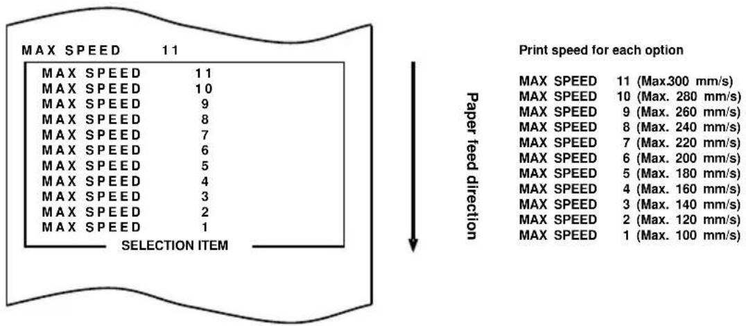
7. Select "5" as your option.
Press the FEED switch briefly (one second or less) until "5" is reached. Then, press and hold down the FEED switch for one second or longer to accept the selection.
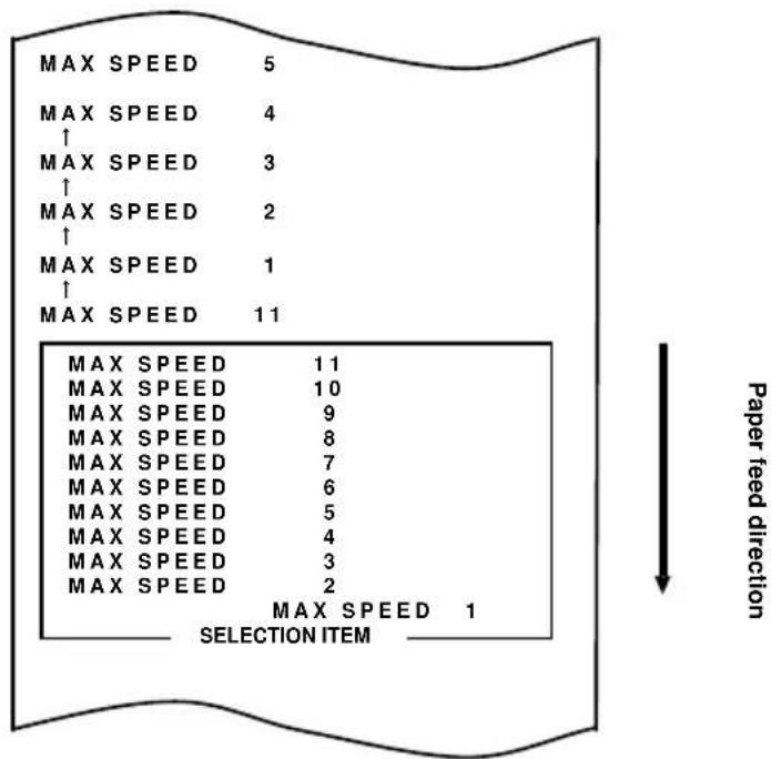
other
| MAX SPEED | 1 | | :--- | :--- | | 5 | MAX SPEED 1 | | 4 | MAX SPEED 2 | | 3 | MAX SPEED 3 | | 2 | MAX SPEED 4 | | 1 | MAX SPEED 5 | | 11 | MAX SPEED 6 | | 11 | MAX SPEED 7 | | 10 | MAX SPEED 8 | | 9 | MAX SPEED 9 | | 8 | MAX SPEED 10 | | 7 | MAX SPEED 11 | | 6 | MAX SPEED 12 | | 5 | MAX SPEED 13 | | 4 | MAX SPEED 14 | | 3 | MAX SPEED 15 | | 2 | MAX SPEED 16 | MAX SPEED 1 → Paper feed direction — selection item —The printer prints the following when you accept the selection of "5":
flowchart
graph TD
    A["RETURN TO UP"] --> B["RETURN TO SETUP MENU"]
    B --> C["RETURN TO UP"]
    C --> D["LOW POWER"]
    D --> E["MAX SPEED"]
    E --> F["BK DENSITY (2COLOR)"]
    F --> G["PRINT DENSITY"]
    G --> H["PRINT COLOR"]
    H --> I["PRINT WIDTH"]
    I --> J["NV GRAPHIC MEMORY"]
    J --> K["USER NV MEMORY"]
    K --> L["SELECTION ITEM"]
    L --> M["Paper feed direction"]
- Select "RETURN TO UP" as your option.
Press and hold down the FEED switch for one second or longer to accept the selection.
The printer prints the following when you accept the selection of "RETURN TO UP":
flowchart
graph TD
    A["RETURN TO SETUP MENU"] --> B["RETURN TO SETUP MENU"]
    B --> C["OTHER"]
    C --> D["SERIAL INTERFACE CONDITION"]
    D --> E["CUSTOMIZE VALUE"]
    E --> F["MEMORY SWITCH"]
    F --> G["SELECTION ITEM"]
    style A fill:#f9f,stroke:#333
    style G fill:#ccf,stroke:#333
    note right of A Paper feed direction
- Select "RETURN TO SETUP MENU" as your option.
Press and hold down the FEED switch for one second or longer to accept the selection.
The printer prints the following when you accept the selection of "RETURN TO SETUP MENU":

flowchart
graph TD
    A["SETTING"] --> B["SAVE&END"]
    A --> C["DEFAULT SET"]
    A --> D["SETUP PRINT"]
    A --> E["SETTING"]
    E --> F["SELECTION ITEM"]
    F --> G["Paper feed direction"]
- Select "SAVE&END" as your option.
Press the FEED switch briefly (one second or less) until the item "SAVE&END" is reached.
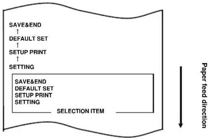
flowchart
graph TD
    A["SAVE&END ↑"] --> B["DEFAULT SET ↑"]
    B --> C["SETUP PRINT ↑"]
    C --> D["SETTING"]
    D --> E["SAVE&END"]
    E --> F["DEFAULT SET"]
    F --> G["SETUP PRINT"]
    G --> H["SETTING"]
    H --> I["SELECTION ITEM"]
    I --> J["Paper feed direction"]
Then, press and hold down the FEED switch for one second or longer to accept the selection.
The printer cuts the paper and exits from setup mode when you accept the selection of "SAVE&END."
Note: If you turn off the printer power switch without first selecting "SAVE&END," your setting will be lost.
- Verifying your setting
To verify your setting, execute a test print, referring to Section C-1. The test printing prints a list of printer settings. Check the list, and verify your setting.
Example (3): Setting required for using two-color thermal paper
Change of the print color setting (from monochrome to two colors)
The procedure for this setting is as follows.
- Before starting work for this setting, verify the following conditions of the printer:
(1) The power is off.
(2) Roll paper is inserted in it.
(3) The cover is closed.
- Enter special mode.
Turn on the power switch on the right side of the printer while holding down the FEED switch on the left part of the Top cover.
The printer prints the following when it enters special mode
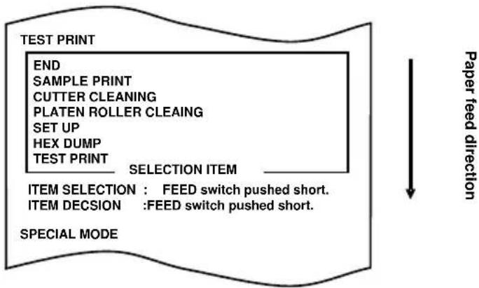
flowchart
graph TD
    A["TEST PRINT"] --> B["END"]
    B --> C["SAMPLE PRINT"]
    C --> D["CUTTER CLEANING"]
    D --> E["PLATEN ROLLER CLEAING"]
    E --> F["SET UP"]
    F --> G["HEX DUMP"]
    G --> H["TEST PRINT"]
    H --> I["SELECTION ITEM"]
    I --> J["ITEM SELECTION : FEED switch pushed short."]
    J --> K["ITEM DECISION :FEED switch pushed short."]
    K --> L["SPECIAL MODE"]
    style A fill:#f9f,stroke:#333
    style L fill:#ccf,stroke:#333
- Enter setup mode from special mode.
Press the FEED switch briefly (one second or less) twice to move to "SET UP."
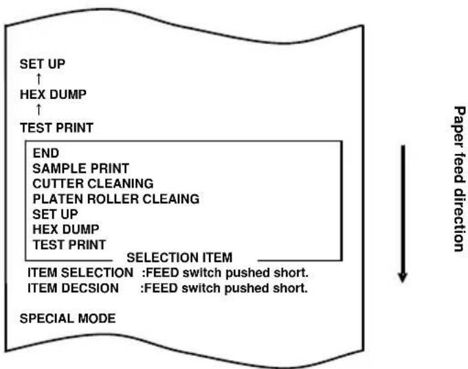
flowchart
graph TD
    A["SET UP"] --> B["HEX DUMP"]
    B --> C["TEST PRINT"]
    C --> D["END"]
    D --> E["SAMPLE PRINT"]
    E --> F["CUTTER CLEANING"]
    F --> G["PLATEN ROLLER CLEAING"]
    G --> H["SET UP"]
    H --> I["HEX DUMP"]
    I --> J["TEST PRINT"]
    J --> K["SELECTION ITEM"]
    K --> L["ITEM SELECTION : FEED switch pushed short."]
    K --> M["ITEM DECISION : FEED switch pushed short."]
    N["SPECIAL MODE"] --> O["Paper feed direction"]
Then, press and hold down the FEED switch for one second or longer to accept the selection.
The printer prints the following when it enters setup mode:
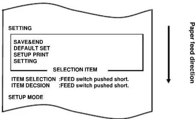
flowchart
graph TD
    A["SETTING"] --> B["SAVE&END"]
    B --> C["DEFAULT SET"]
    C --> D["SETUP PRINT"]
    D --> E["SETTING"]
    E --> F["SELECTION ITEM"]
    F --> G["ITEM SELECTION : FEED switch pushed short."]
    F --> H["ITEM DECISION : FEED switch pushed short."]
    I["SETUP MODE"] --> F
    J["Paper feed direction"] --> K
- In setup mode, select "SETTING."
Press and hold down the FEED switch for one second or longer to accept the selection.
The printer prints the following when you accept the selection of "SETTING":
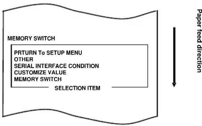
flowchart
graph TD
    A["MEMORY SWITCH"] --> B["PRETURN TO SETUP MENU"]
    B --> C["OTHER"]
    C --> D["SERIAL INTERFACE CONDITION"]
    D --> E["CUSTOMIZE VALUE"]
    E --> F["MEMORY SWITCH"]
    F --> G["SELECTION ITEM"]
    G --> H["Paper feed direction"]
- Select "CUSTOMIZE VALUE" as your option.
Press the FEED switch briefly (one second or less) until the item "CUSTOMIZE VALUE" is reached.
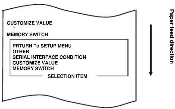
flowchart
graph TD
    A["Customize VALUE ↑ MEMORY SWITCH"] --> B["PRETURN TO SETUP MENU OTHER SERIAL INTERFACE CONDITION CUSTOMIZE VALUE MEMORY SWITCH"]
    B --> C["SELECTION ITEM"]
    D["Paper feed direction"] --> E["↓"]
Then, press and hold down the FEED switch for one second or longer to accept the selection.
The printer prints the following when you accept the selection of "CUSTOMIZE VALUE":
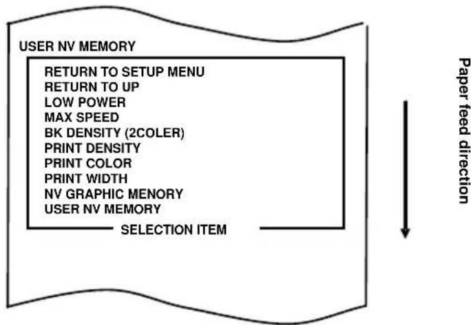
flowchart
graph TD
    A["USER NV MEMORY"] --> B["RETURN TO SETUP MENU"]
    B --> C["RETURN TO UP"]
    C --> D["LOW POWER"]
    D --> E["MAX SPEED"]
    E --> F["BK DENSITY (2COLER)"]
    F --> G["PRINT DENSITY"]
    G --> H["PRINT COLOR"]
    H --> I["PRINT WIDTH"]
    I --> J["NV GRAPHIC MEMORY"]
    J --> K["USER NV MEMORY"]
    K --> L["SELECTION ITEM"]
    L --> M["Paper feed direction"]
- Select "PRINT COLOR" as your option.
Press the FEED switch briefly (one second or less) three times to move to "PRINT COLOR."
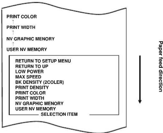
flowchart
graph TD
    A["PRINT COLOR"] --> B["PRINT WIDTH"]
    B --> C["NV GRAPHIC MEMORY"]
    C --> D["USER NV MEMORY"]
    D --> E["RETURN TO SETUP MENU"]
    E --> F["RETURN TO UP"]
    F --> G["LOW POWER"]
    G --> H["MAX SPEED"]
    H --> I["BK DENSITY (2COLER)"]
    I --> J["PRINT DENSITY"]
    J --> K["PRINT COLOR"]
    K --> L["PRINT WIDTH"]
    L --> M["NV GRAPHIC MEMORY"]
    M --> N["USER NV MEMORY"]
    N --> O["SELECTION ITEM"]
    style A fill:#f9f,stroke:#333
    style B fill:#f9f,stroke:#333
    style C fill:#f9f,stroke:#333
    style D fill:#f9f,stroke:#333
    style E fill:#ccf,stroke:#333
    style F fill:#ccf,stroke:#333
    style G fill:#ccf,stroke:#333
    style H fill:#ccf,stroke:#333
    style I fill:#ccf,stroke:#333
    style J fill:#ccf,stroke:#333
    style K fill:#ccf,stroke:#333
    style L fill:#ccf,stroke:#333
    style M fill:#ccf,stroke:#333
    style N fill:#ccf,stroke:#333
    style O fill:#ccf,stroke:#333
Then, press and hold down the FEED switch for one second or longer to accept the selection.
The printer prints the following when you accept the selection of "PRINT COLOR":
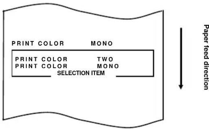
- Select "TWO" as your option.
Press the FEED switch briefly (one second or less) until "TWO" is reached.
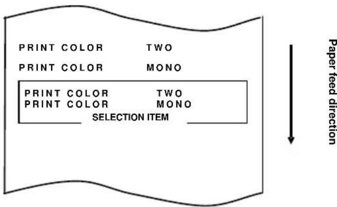
Then, press and hold down the FEED switch for one second or longer to accept the selection.
The printer prints the following when you accept the selection of "TWO":
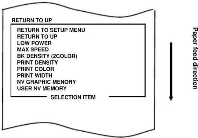
flowchart
graph TD
    A["RETURN TO UP"] --> B["RETURN TO SETUP MENU"]
    B --> C["RETURN TO UP"]
    C --> D["LOW POWER"]
    D --> E["MAX SPEED"]
    E --> F["BK DENSITY (2COLOR)"]
    F --> G["PRINT DENSITY"]
    G --> H["PRINT COLOR"]
    H --> I["PRINT WIDTH"]
    I --> J["NV GRAPHIC MEMORY"]
    J --> K["USER NV MEMORY"]
    K --> L["SELECTION ITEM"]
    style A fill:#f9f,stroke:#333
    style L fill:#ccf,stroke:#333
- Select "RETURN TO UP" as your option.
Press and hold down the FEED switch for one second or longer to accept the selection.
The printer prints the following when you accept the selection of "RETURN TO UP":
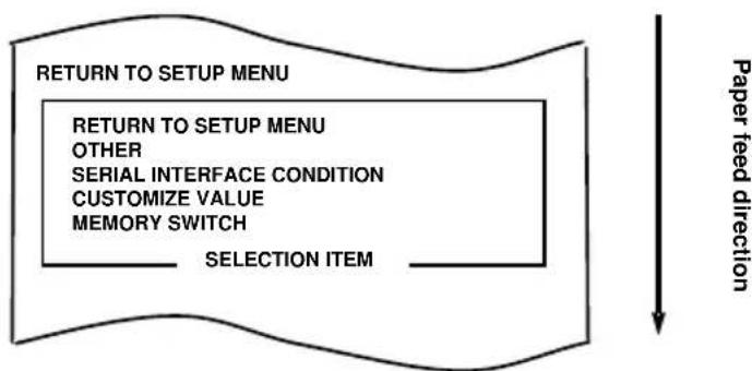
flowchart
graph TD
    A["RETURN TO SETUP MENU"] --> B["RETURN TO SETUP MENU"]
    B --> C["OTHER"]
    C --> D["SERIAL INTERFACE CONDITION"]
    D --> E["CUSTOMIZE VALUE"]
    E --> F["MEMORY SWITCH"]
    F --> G["SELECTION ITEM"]
    style A fill:#f9f,stroke:#333
    style G fill:#ccf,stroke:#333
    note right of A Paper feed direction
- Select "RETURN TO SETUP MENU" as your option.
Press and hold down the FEED switch for one second or longer to accept the selection.
The printer prints the following when you accept the selection of "RETURN TO SETUP MENU":
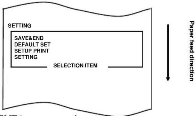
flowchart
graph TD
    A["SETTING"] --> B["SAVE&END"]
    B --> C["DEFAULT SET"]
    C --> D["SETUP PRINT"]
    D --> E["SETTING"]
    E --> F["SELECTION ITEM"]
    F --> G["Paper feed direction"]
- Select "SAVE&END" as your option.
Press the FEED switch briefly (one second or less) until the item "SAVE&END" is reached.
Then, press and hold down the FEED switch for one second or longer to accept the selection.
The printer cuts the paper and exits from setup mode when you accept the selection of "SAVE&END."
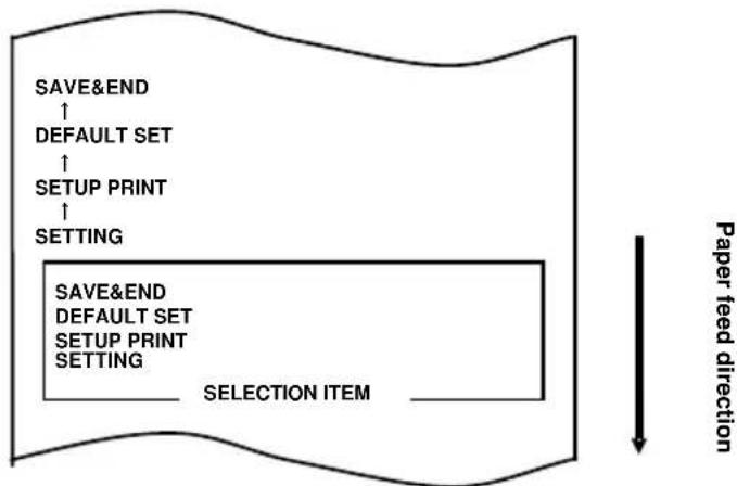
flowchart
graph TD
    A["SAVE&END ↑"] --> B["DEFAULT SET ↑"]
    B --> C["SETUP PRINT ↑"]
    C --> D["SETTING"]
    E["SAVE&END DEFAULT SET SETUP PRINT SETTING"] --> F["SELECTION ITEM"]
    style E fill:#f9f,stroke:#333
    style F fill:#ccf,stroke:#333
    note right of E Paper feed direction
Note: If you turn off the printer power switch without first selecting "SAVE&END," your setting will be lost.
- Verifying your setting
To verify your setting, execute a test print, referring to Section C-1. The test printing prints a list of printer settings. Check the list, and verify your setting.
C-4.Setup Items
Setup group items
| No. | Setup group item Explanation | |
| 1 | MEMORY SWITCH Enters the mode for MEMORY SWITCH-related settings. | |
| 2 | CUSTOMIZE VALUE Enters the mode for CUSTOMIZE VALUE-related settings. | |
| 3 | SERIAL INTERFACE CONDITION | Enters the mode for SERIAL INTERFACE CONDITION-related settings. |
| 4 | OTHER Enters the mode for other types of settings. | |
| 5 | RETURN TO SETUP MENU Returns to the setup mode menu. | |
Setup items and their details
(1) MEMORY SWITCH setup items
| No. | Item | Explanation | Detail Setup Item | |
| 1 | POWER ON STATUS | - Specifies reporting the power-on state. ENABLE | DISABLE | |
| 2 | RECEIVE BUFFER | - Specifies the capacity of the receive buffer. 45BYTE | 4KBYTE | |
| 3 | BUSY CONDITION | - Status designation when printer turn is busy.BUFFERFULL:Turns busy when receive buffer is full.OFFLINE/BUFFERFULL:Turns busy when receive buffer is full or off-line. | BUFFERFULLOFFLINE/BFUUERFULL | |
| 4 | RECEIVE ERROR | - Specifies how to handle receive errors- This item is valid only for the serial interface. | IGNORE?PRINT | |
| 5 | AUTO LF | - Specifies automatic line feed using the CR code.- This item is valid only for the Parallel interface. | ENABLE DISABLE | |
| 6 | DSR(#6) RESET | - Specifies the reset operation using the DSR (#6) signal.- This item is valid only for the serial interface. | ENABLE DISABLE | |
| 7 | INIT(#25) RESET | - Specifies the reset operation using the INIT (#25) signal.- This item is valid only for the serial interface. | ENABLE DISABLE | |
| 8 | INIT(#31) RESET | - Specifies reset using the INIT (#31) signal.- This item is valid only for the parallel interface. | ENABLE DISABLE | |
| 9 | COVER OPEN ERROR | - Specifies how to handle a cover open error during printing.AUTO RECOVERY:When a cover is closed, Printer is recovery automaticity.RECOVERY BY CMND:When a cover is closed, Printer is recovery by command. | AUTO RECOVERYRECOVERY BY CMND | |
| 10 | BM CHECK AT POW-ON | - Specifies the adjustment of the leading edge of the paper at power-on.- This item is valid only when the black mark detection unit is installed and "BM sensor installed" is set. | ENABLE DISABLE | |
| 11 | RETURN TO UP | - Returns the menu to the selection mode for setup group items. | - | |
| 12 | RETURN TO SETUP MENU | - Returns the menu to the setup mode menu. | - | |
(2) CUSTOMIZE VALUE setup items
| No. | Item | Explanation | Detail setup item |
| 1 | USER NV MEMORY | - Capacity of the user NV memory. | 1KBYTE 64KBYTE,128KBYTE 192KBYTE |
| 2 | NV GRAPHIC MEMORY | - Capacity of the NV graphic memory. | None64KBYTE 128KBYTE192KBYTE 256KBYTE320KBYTE 384KBYTE |
| 3 | PAPER WIDTH - Paper | width and number of columns used. | 83mm/53 columns80mm/48 columns80mm/42 columns60mm/36 columns58mm/35 columns58mm/32 columns |
| 4 | PRINT COLOR - Print colors. | MONOTWO | |
| 5 | PRINT DENSITY - Print density.* 70% is the lowest density.130% is the highest density. | 70% 75% 80% 85%90% 95% 100% 105%110% 115% 120% 125%130% | |
| 6 | BK DENSITY (2COLOR) | - Black density when "TWO" is set for PRINT COLOR.* 70% is the lowest density.130% is the highest density. | 70% 75% 80% 85%90% 95% 100% 105%110% 115% 120% 125%130% |
| 7 | MAX SPEED - Maximum print speed.* 1(100mm/s) is the lowest print speed and 11(300mm/s) is the highest print speed. | 1 2 3 4 56 7 8 9 1011 | |
| 8 | LOW POWER - Setting for reducing power consumption.MODE1:Reduction of about 10%MODE2:Reduction of about 30% | NORMALMODE1MODE2 | |
| 9 | BUZZER INTERVAL | -Set a buzzer tone in the printPushed down FEED switch in a cover opening state and receive a buzzer command,(ESC p 03h t1 t2 t3)the buzzer in the print sounds | PATTERN 1PATTERN 2PATTERN 3PATTERN 4PATTERN 5 |
| 10 | BUZZER REPETITION | -A buzzer sets the number of times to sound in print.Pushed down FEED switch in a cover opening state and receive a buzzer command,(ESC p 03h t1 t2 t3)the buzzer in the print sounds | ZEROONETWOTHREEFOURFIVE |
| 11 | RETURN TO UP - Returns to the selection mode for the setup group items. | ||
| 12 | RETURN TO SETUP MENU | - Returns to the setup menu. | |
(3) SERIAL INTERFACE CONDITION setup items
| No. | Item | Explanation | Detail setup item |
| 1 | BAUDRATE - Baud rate. 2400BPS 4800BPS | 9600BPS 19200BPS38400BPS 57600BPS115200BPS | |
| 2 | FORMAT - Data format. 7EVEN1 7ODD1 | 8NONE1 8EVEN18ODD1 | |
| 3 | PROTOCOL - Buffer control protocol. XON/XOFF | DSR/DTR | |
| 4 | RETURN TO UP - Returns to the selection mode for the setup group items. | - | |
| 5 | RETURN TO SETUP MENU | - Returns to the setup mode. | - |
(4) OTHER setup items
| No. | Item | Explanation | Detail | setup item |
| 1 | ACK PULSE WIDTH | - Specifies the ACK pulse width. 1μs | 8μs | |
| 2 | USB - Specifies the use of the USB connection.V-COM : Virtual COM class.PRINTER: Printer class. | V-COM PRINTER | ||
| 3 | SERIAL NUMBER - Specifies the type of Serial Number notification in a USB connection.Generally, specify "DISABLE." | ENABLE DISABLE | ||
| 4 | ERROR - Specifies the mode for the power-on time and the error recovery time.AUTO RECOVERY:Windows drivers are used.RECOVERY BY CMND:OPOS drivers are used. | AUTO RECOVERYRECOVERY BY CMND | ||
| 5 | PROCESS ID - Specifies a process ID.NORMAL:Responds with the process ID at the end of printing.HI-SPEED:Responds with the process ID at the end of data reception. | NORMAL HI-SPEED | ||
| 6 | PNE DETECT - Specifies whether to report the Paper-near-end condition. | ENABLE DISABLE | ||
| 7 | FONT B - Specifies Font B.MODE 1: Font in the standard specifications MODE 2: Other font | MODE 1 MODE 2 | ||
| 8 | BATCH (COM IF) | - ENABLE:Received data is printed in a batch.- DISABLE:Received data is printed serially.* This item is valid only with the serial interface. | ENABLE DISABLE | |
| 9 | BATCH (OTHER IF) | - ENABLE:Received data is printed in a batch.- DISABLE:Received data is printed serially.* This item is valid only with the USB, parallel or LAN interface. | ENABLE DISABLE | |
| 10 | CUTTER MODE | - Specifies the mode for cutter operation.* This item is valid only for models supporting both full cutting and partial cutting. | PARTIAL FULL | |
| 11 | BM SENSOR | - Specifies whether the BM sensor has been installed.Set "INSTALLED" only when the BM sensor has been installed.(This item is valid only for a device specified to have the BM sensor installed.) | INSTALLEDUNINSTALLED | |
| 12 | BM CHEK WITH CUT | - Specifies the cut operation initiated by the BM sensor.This setting is effective only when "INSTALLED" has been set for BM SENSOR.(This item is valid only for a device specified to have the BM sensor installed.) | ENABLE DISABLE | |
| 13 | BUZZER - Specifies whether to sound the buzzer at error occurrence.The buzzer can be sounded by a command even if "DISABLE" is specified. (This item is valid only for a device specified to have a buzzer installed.) | DISABLE ENABLE | ||
| 14 | RETURN TO UP - Returns to the selection mode for the setup group items. | - | ||
| 15 | RETURN TO SETUP MENU | - Returns to the setup mode menu. - | ||
C-5.Sample Print
With paper inserted in the printer, turn off the printer power switch once. If you turn on the switch again while holding down the FEED switch on the control panel, the data shown in Section C-1 will be printed. If you turn on the switch again and press the FEED switch briefly, the data shown below will be printed.
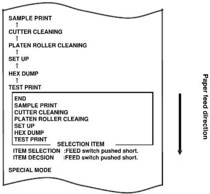
flowchart
graph TD
    A["SAMPLE PRINT"] --> B["CUTTER CLEANING"]
    B --> C["PLATEN ROLLER CLEANING"]
    C --> D["SET UP"]
    D --> E["HEX DUMP"]
    E --> F["TEST PRINT"]
    F --> G["END"]
    G --> H["SAMPLE PRINT"]
    H --> I["CUTTER CLEANING"]
    I --> J["PLATEN ROLLER CLEANING"]
    J --> K["SET UP"]
    K --> L["HEX DUMP"]
    L --> M["TEST PRINT"]
    M --> N["SELECTION ITEM"]
    N --> O["ITEM SELECTION : FEED switch pushed short."]
    N --> P["ITEM DECISION : FEED switch pushed short."]
    Q["SPECIAL MODE"] --> R["Paper feed direction"]
When "SAMPLE PRINT" is printed, press and hold down the FEED switch for one second or longer to place the printer in sample print mode.
The printed pattern is as follows.
a) Receipt pattern
b) Coupon pattern
c) Barcode pattern
When the FEED switch is pressed short, the following pattern is printed.
“Receipt”→“Coupon”→“Barcode”→“Receipt”→···
When the FEED switch is pressed long (about one second), the same pattern is printed again.
The printed pattern is changed by setup "Paper Width" setting.
83mm/53columns -> Pattern 80mm
80mm/48columns -> Pattern 80mm
80mm/42columns -> Pattern 80mm
60mm/36columns -> Pattern 58mm
58mm/35columns -> Pattern 58mm
58mm/32columns -> Pattern 58mm
The sample print mode is ended by the printer power supply determination.
Printed result of sample printings
"Receipt" pattern(80mm)

“Coupon” pattern(80mm)

"Barcode" pattern(80mm)

"Receipt" pattern (58mm)
"Coupon" pattern (58mm)


"Barcode" pattern (58mm)
Oki Systems (UK) Ltd
Blays House
Wick Road
Egham
Surrey
TW20 0HJ
Tel: +44 (0) 1784 274300
Fax: +44 (0) 1784 274301
http://www.oki.co.uk
Oki Systems Ireland Limited
The Square Industrial Complex Tallaght
Dublin 24
Tel: +353 (0) 1 4049590
Fax: +353 (0)1 4049591
http://www.oki.ie
Oki Systems Ireland Limited - Northern Ireland
19 Ferndale Avenue
Glengormley
BT36 5AL
Northern Ireland
Tel: +44 (0) 7767 271447
Fax: +44 (0) 1 404 9520
http://www.oki.ie
Technical Support for all Ireland:
Tel: +353 1 4049570
Fax: +353 1 4049555
E-mail: tech.support@oki.ie
OKI Systems (Czech and Slovak), s.r.o.
Futurama Business Park -
Sokolovská 651/136A
186 00 Praha 8
Czech Republic
Tel: +420 224 890158
Fax:+420 22 232 6621
Website: www.oki.cz, www.oki.sk
Albania, Bosnia, Bulgaria, Croatia,
Cyprus, Estonia, Greece, Israel,
Latvia, Lithuania, Macedonia,
Romania, Serbia, Slovenia
CEE Export Group: OKI Systems (Poland) Ltd
ul. Domaniewska 42
02-672 Warsaw
Poland
Tel: +48 (0) 22 448 65 00
Fax: +48 (0) 22 448 65 0
E-mail: tech@oki.com.pl
Platinum Business Park II, 3rd Floor
ul. Domaniewska 42
02-672 Warsaw
Poland
Tel: +48 22 448 65 00
Fax: +48 22 448 65 01
Website: www.oki.com.pl
E-mail: oki@oki.com.pl
Hotline: 0800 120066
E-mail: tech@oki.com.pl
OKI Systems Rus, LLC (Russia)
Sector B, 3rd Floor, Svyatogor-4
Business Center10/4, Letnikovskaya
str.115114, Moscow
Tel: +7 495 276 5060
Fax: +7 495 258 6070
e-mail: info@oki.ru
Website: www.oki.ru
Technical support:
Tel: +7 495 564 8421
e-mail: tech@oki.ru
Raisy Opkinoy Street,8
Building B, 2 ^nd Floor,
Kiev 02002
Ukraine
Tel: +380 44 537 5288
e-mail: event@oki.ua
Website: www.oki.ua
Oki Systems (Belgium)
Medialaan 24
1800 Vilvoorde
Helpdesk: 02-2574620
Fax: 02 2531848
Website: www.oki.be
OKI Systems (Danmark) a·s
Herstedøstervej 27
2620 Albertslund
Danmark
Oki Systems (Norway) AS
Tevlingveien 23
N-1081 Oslo
Tel: +47 (0) 63 89 36 00
Telefax: +47 (0) 63 89 36 01
Website: www.oki.no
Var vänlig kontakta din
Oki Systems (Sweden) AB
Borgafjordsgatan 7
Box 1193
164 26 Kista
Tel. +46 (0) 8 634 37 00
e-mail: info@oki.se
Website: www.oki.se
2000 Bishops Gate Blvd.
http://WWW.OKIPRINTINGSOLUTIONS.COM
http://my.okidata.com
Oki Data Americas Inc.(Canada • Canadá)
4140B Sladeview Crescent Unit 7 & 8
Mississauga, Ontario
Canada L5L 6A1
Tél: 1-905-608-5000
Téléc: 1-905-608-5040
http://WWW.OKIPRINTINGSOLUTIONS.COM
Oki Data Americas Inc.(América Latina (OTRO))
2000 Bishops Gate Blvd.
HTTP://www.okiprintingsolutions.com
Argentina/ Chile/ Paraguay/ Perú/ Uruguay
Oki Data Americas, Inc.
Sucursal Argentina
Ugarte 3610 Piso 4°(1605) Olivos
Buenos Aires, Argentina
TEL: +54 11 5288 7500
Fax: +54 11 5288 7599
Colombia/ Ecuador/ Venezuela/ Centroamérica y Caribe Oki Data Americas, Inc.
Sucursal Colombia
1168/81-82 Lumpini Tower,
27th Floor Rama IV Road
Tungmahamek, Sathorn
Bangkok 10120
Tel: (662) 679 9235
Fax: (662) 679 9243/245
http://www.okisysthai.com
Oki Data(Australia) Pty Ltd.
Level1 67 Epping Road, Macquare Park
NSW 2113, Australia
Tel: +61 2 8071 0000
(Support Tel: 1800 807 472)
Fax: +61 2 8071 0010
http://www.oki.com.au
OKI Data New Zealand
8 Antares Place Rosedale,
Auckland, 0632 New Zealand
Tel: (64) 9 477 0500
Fax: (64) 9 477 0549
http://www.oki.co.nz/
Oki Data(S) P Ltd. Malaysia Rep Office
Suite 21.03, 21st Floor Menara IGB, Mid Valley City,
Lingkaran Syed Pura 59200,
Kuala Lumpur, Malaysia
Tel: (60) 3 2287 1177
Fax: (60) 3 2287 1166
PT390
OKI
© 2011 Oki Data Corporation
OKI Data Corporation,
4-11-22 Shibaura, Minato-ku,
Tokyo 108-8551,
Japon
natural_image
Simple geometric diagram with concentric circles and a diagonal line inside a diamond shape (no text or symbols)UTILITAIRE DU PILOTE D'IMPRIMANTE MANUEL

natural_image
Simple geometric diamond shape outline with no text or symbolsnatural_image
Simple geometric diamond shape with no text or symbols
natural_image
Technical line drawing of a mechanical device with a coiled spring and housing (no text or symbols)
natural_image
Simple line drawing of a rope tied with a string, no text or symbols presentnatural_image
Diagram of a robotic arm with motion lines indicating movement, no text or symbols presentnatural_image
Close-up of a hand holding a black USB cable (no text or symbols visible)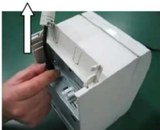
natural_image
Hand inserting a black plastic component into a white electronic device casing (no text or symbols visible)natural_image
Technical line drawing of two open battery compartments with a circular component on the left (no text or symbols)natural_image
Close-up of a mechanical component with internal structure and mounting holes (no visible text or symbols)natural_image
Close-up of a mechanical component with internal structure and mounting holes (no visible text or symbols)natural_image
Technical line drawing of a mechanical device with an open lid and internal components, showing no text or symbols.natural_image
Line drawing of an open industrial machine with a cross symbol indicating cancellation (no text or labels present)natural_image
Technical line drawing of an open industrial machine with a circular component inside (no text or symbols)natural_image
Simple line drawings of circular and cross symbols (no text or labels)natural_image
Close-up of a white plastic panel with black insulation and a black connector, against a green background (no text or symbols visible)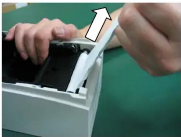
natural_image
Close-up of hands installing or adjusting a device into a white plastic container with black casing, no visible text or symbolsnatural_image
Hand placing a white plastic component into a white paper holder (no visible text or symbols)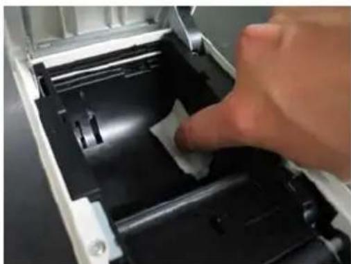
natural_image
Close-up of a hand pressing down on a black plastic electronic device casing (no visible text or symbols)natural_image
Two types of screwdriver tools on a dark surface, one with a metallic tip and the other with a wooden handle (no text or symbols visible)
natural_image
Close-up of a mechanical component with a tool interacting with a textured surface (no visible text or symbols)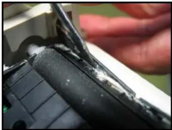
natural_image
Close-up of a hand using a tool to repair a damaged black object, no visible text or symbolsnatural_image
Simple line drawing of a building outline with vertical supports (no text or symbols)(4) Commutateur DIP
BUSY CONDITION BUFFERFULL
RECEIVE ERROR ?PRINT
AUTO LF DISABLE
DSR(#6) RESET DISABLE
•
.
C-2. Vidage hexadécimal
Modèle
« Coupon » (58 mm)

Modèle
Oki Systems (UK) Ltd
Blays House
Wick Road
Egham
Surrey
TW20 0HJ
Tel: +44 (0) 1784 274300
Fax: +44 (0) 1784 274301
http://www.oki.co.uk
Oki Systems Ireland Limited
The Square Industrial Complex Tallaght
Dublin 24
Tel: +353 (0) 1 4049590
Fax: +353 (0)1 4049591
http://www.oki.ie
Oki Systems Ireland Limited - Northern Ireland
19 Ferndale Avenue
Glengormley
BT36 5AL
Northern Ireland
Tel: +44 (0) 7767 271447
Fax: +44 (0) 1 404 9520
http://www.oki.ie
Technical Support for all Ireland:
Tel: +353 1 4049570
Fax: +353 1 4049555
E-mail: tech.support@oki.ie
OKI Systems (Czech and Slovak), s.r.o.
Futurama Business Park - Sokolovská 651/136A
186 00 Praha 8
Czech Republic
Tel: +420 224 890158
Fax:+420 22 232 6621
Website: www.oki.cz, www.oki.sk
Albania, Bosnia, Bulgaria, Croatia,
Cyprus, Estonia, Greece, Israel,
Latvia, Lithuania, Macedonia,
Romania, Serbia, Slovenia
CEE Export Group: OKI Systems (Poland) Ltd
ul. Domaniewska 42
02-672 Warsaw
Poland
Tel: +48 (0) 22 448 65 00
Fax: +48 (0) 22 448 65 0
E-mail: tech@oki.com.pl
Platinum Business Park II, 3rd Floor
ul. Domaniewska 42
02-672 Warsaw
Poland
Tel: +48 22 448 65 00
Fax: +48 22 448 65 01
Website: www.oki.com.pl
E-mail: oki@oki.com.pl
Hotline: 0800 120066
E-mail: tech@oki.com.pl
OKI Systems Rus, LLC (Russia)
Sector B, 3rd Floor, Svyatogor-4
Business Center10/4, Letnikovskaya
str.115114, Moscow
Tel: +7 495 276 5060
Fax: +7 495 258 6070
e-mail: info@oki.ru
Website: www.oki.ru
Technical support:
Tel: +7 495 564 8421
e-mail: tech@oki.ru
Raisy Opkinoy Street,8
Building B, 2 ^nd Floor,
Kiev 02002
Ukraine
Tel: +380 44 537 5288
e-mail: event@oki.ua
Website: www.oki.ua
Oki Systems (Belgium)
Medialaan 24
1800 Vilvoorde
Helpdesk: 02-2574620
Fax: 02 2531848
Website: www.oki.be
OKI Systems (Danmark) a·s
Herstedøstervej 27
2620 Albertslund
Danmark
Oki Systems (Norway) AS
Tevlingveien 23
N-1081 Oslo
Tel: +47 (0) 63 89 36 00
Telefax: +47 (0) 63 89 36 01
Website: www.oki.no
Var vänlig kontakta din
Oki Systems (Sweden) AB
Borgafjordsgatan 7
Box 1193
164 26 Kista
Tel. +46 (0) 8 634 37 00
e-mail: info@oki.se
Website: www.oki.se
2000 Bishops Gate Blvd.
http://WWW.OKIPRINTINGSOLUTIONS.COM
http://my.okidata.com
Oki Data Americas Inc.(Canada • Canadá)
4140B Sladeview Crescent Unit 7 & 8
Mississauga, Ontario
Canada L5L 6A1
Tél: 1-905-608-5000
Téléc: 1-905-608-5040
http://WWW.OKIPRINTINGSOLUTIONS.COM
Oki Data Americas Inc.(América Latina (OTRO))
2000 Bishops Gate Blvd.
HTTP://www.okiprintingsolutions.com
Argentina/ Chile/ Paraguay/ Perú/ Uruguay
Oki Data Americas, Inc.
Sucursal Argentina
Ugarte 3610 Piso 4°(1605) Olivos
Buenos Aires, Argentina
TEL: +54 11 5288 7500
Fax: +54 11 5288 7599
Colombia/ Ecuador/ Venezuela/ Centroamérica y Caribe Oki Data Americas, Inc.
Sucursal Colombia
1168/81-82 Lumpini Tower,
27th Floor Rama IV Road
Tungmahamek, Sathorn
Bangkok 10120
Tel: (662) 679 9235
Fax: (662) 679 9243/245
http://www.okisysthai.com
Oki Data(Australia) Pty Ltd.
Level1 67 Epping Road, Macquare Park
NSW 2113, Australia
Tel: +61 2 8071 0000
(Support Tel: 1800 807 472)
Fax: +61 2 8071 0010
http://www.oki.com.au
OKI Data New Zealand
8 Antares Place Rosedale,
Auckland, 0632 New Zealand
Tel: (64) 9 477 0500
Fax: (64) 9 477 0549
http://www.oki.co.nz/
Oki Data(S) P Ltd. Malaysia Rep Office
Suite 21.03, 21st Floor Menara IGB, Mid Valley City,
Lingkaran Syed Pura 59200,
Kuala Lumpur, Malaysia
Tel: (60) 3 2287 1177
Fax: (60) 3 2287 1166
PT390
OKI
Manuale d'uso
PREFAZIONE
© 2011 Oki Data Corporation
OKI Data Corporation,
4-11-22 Shibaura, Minato-ku,
Tokyo 108-8551,
Giappone
natural_image
Simple line drawing of a cylindrical object with a central hole (no text or symbols)Carta termica CD
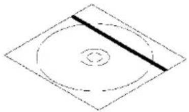
natural_image
Simple geometric diagram with concentric circles and a diagonal line, no text or symbols present.MANUALE
DRIVER STAMPANTE
UTILITY

natural_image
Simple geometric diamond shape with no text or symbolsnatural_image
Simple geometric diamond shape with no text or symbolssicurezza
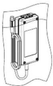
natural_image
Technical line drawing of a mechanical device with no visible text or symbolsnatural_image
Simple line drawing of a rope tied around a small object, no text or symbols presentnatural_image
Diagram of a robot's head and torso assembly with an upward arrow, showing internal components (no text or labels)natural_image
Close-up of a hand holding a black USB cable (no text or symbols visible)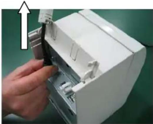
natural_image
Hand inserting a black cable into a white electronic device casing (no text or symbols visible)natural_image
Line drawing of an open mechanical device with a circular component on the left (no text or symbols)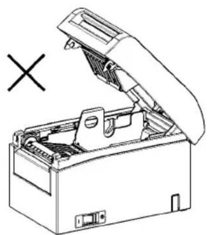
natural_image
Line drawing of an open toolbox with a cross mark and a symbol (X) in the background, no text or labels present.natural_image
Technical line drawing of a mechanical device with an open lid and internal components, showing no text or symbols.natural_image
Technical line drawing of a printer with open lid and internal mechanism (no text or symbols)natural_image
Technical line drawing of a mechanical device with open lid and internal components, no text or symbols presentnatural_image
Two abstract circular patterns: one with a curved line and the other with a cross, both without any text or symbols.natural_image
Close-up of a white plastic panel or holder with black insulation, showing internal structure and mounting brackets (no text or symbols visible)
natural_image
Close-up of hands installing or adjusting a device into a white plastic container (no visible text or symbols)natural_image
Close-up of a hand placing a white plastic sheet into a black plastic container (no text or symbols visible)
natural_image
Close-up of a hand pressing down on a mechanical component with a white plastic clip (no visible text or symbols)natural_image
Close-up of a hand pressing down on a white plastic sheet inside a black electronic device (no text or symbols visible)natural_image
Two types of screwdrivers on a dark surface, one with a blue handle and the other with a black clip (no text or symbols visible)
flowchart
graph TD
    A["CUTTER CLEANING"] --> B["1. Open Cover, and remove Roll Paper"]
    A --> C["2. Push FEED switch to move Cutter to the cleaning position"]
    A --> D["3. When cleaning is completed, set Roll Paper, and close Cover"]
    E["Direzione di caricamento della carta"] --> A
natural_image
Simple line drawing of a rectangular shape with internal vertical lines (no text or symbols)BUSY CONDITION BUFFERFULL
RECEIVE ERROR ?PRINT
AUTO LF DISABLE
DSR(#6) RESET DISABLE
.
.
other
| Selection Item | MAX SPEED | |---|---| | MAX SPEED | 11 | | MAX SPEED | 10 | | MAX SPEED | 9 | | MAX SPEED | 8 | | MAX SPEED | 7 | | MAX SPEED | 6 | | MAX SPEED | 5 | | MAX SPEED | 4 | | MAX SPEED | 3 | | MAX SPEED | 2 | | MAX SPEED | 1 | The image contains a schematic diagram showing a selection item and directional arrow. The text 'Direzione di caricamento della carta' is displayed on the right side. Below it, the table provides the maximum speed value for each item. The text also includes a list of velocity values in mm/s for each item. The chart is labeled 'MAX SPEED' and is accompanied by a vertical annotation box.Motivo "Coupon" (80 mm)

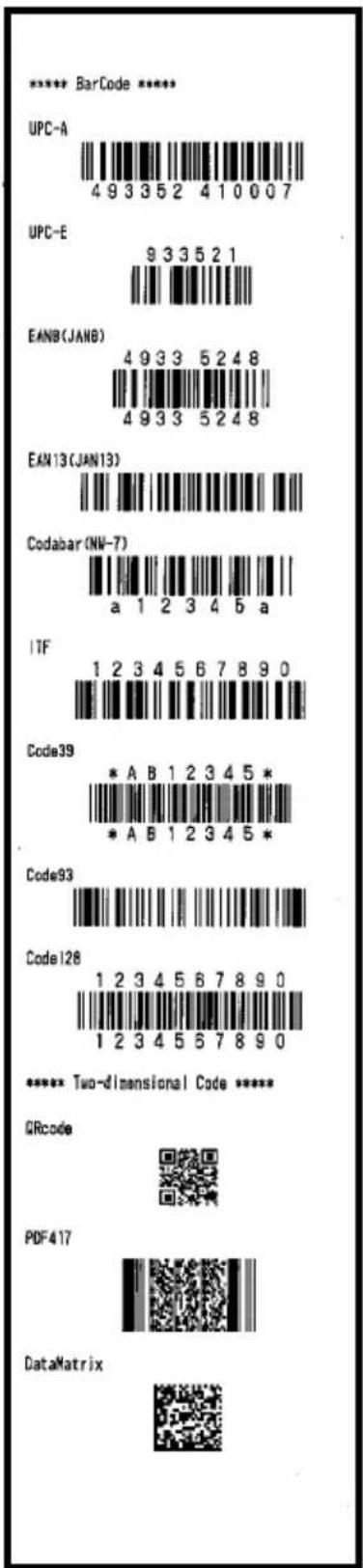
Oki Systems (UK) Ltd
Blays House
Wick Road
Egham
Surrey
TW20 0HJ
Tel: +44 (0) 1784 274300
Fax: +44 (0) 1784 274301
http://www.oki.co.uk
Oki Systems Ireland Limited
The Square Industrial Complex Tallaght
Dublin 24
Tel: +353 (0) 1 4049590
Fax: +353 (0)1 4049591
http://www.oki.ie
Oki Systems Ireland Limited - Northern Ireland
19 Ferndale Avenue
Glengormley
BT36 5AL
Northern Ireland
Tel: +44 (0) 7767 271447
Fax: +44 (0) 1 404 9520
http://www.oki.ie
Technical Support for all Ireland:
Tel: +353 1 4049570
Fax: +353 1 4049555
E-mail: tech.support@oki.ie
OKI Systems (Czech and Slovak), s.r.o.
Futurama Business Park -
Sokolovská 651/136A
186 00 Praha 8
Czech Republic
Tel: +420 224 890158
Fax:+420 22 232 6621
Website: www.oki.cz, www.oki.sk
Albania, Bosnia, Bulgaria, Croatia,
Cyprus, Estonia, Greece, Israel,
Latvia, Lithuania, Macedonia,
Romania, Serbia, Slovenia
CEE Export Group: OKI Systems (Poland) Ltd
ul. Domaniewska 42
02-672 Warsaw
Poland
Tel: +48 (0) 22 448 65 00
Fax: +48 (0) 22 448 65 0
E-mail: tech@oki.com.pl
Platinum Business Park II, 3rd Floor
ul. Domaniewska 42
02-672 Warsaw
Poland
Tel: +48 22 448 65 00
Fax: +48 22 448 65 01
Website: www.oki.com.pl
E-mail: oki@oki.com.pl
Hotline: 0800 120066
E-mail: tech@oki.com.pl
OKI Systems Rus, LLC (Russia)
Sector B, 3rd Floor, Svyatogor-4
Business Center10/4, Letnikovskaya
str.115114, Moscow
Tel: +7 495 276 5060
Fax: +7 495 258 6070
e-mail: info@oki.ru
Website: www.oki.ru
Technical support:
Tel: +7 495 564 8421
e-mail: tech@oki.ru
Raisy Opkinoy Street,8
Building B, 2 ^nd Floor,
Kiev 02002
Ukraine
Tel: +380 44 537 5288
e-mail: event@oki.ua
Website: www.oki.ua
Oki Systems (Belgium)
Medialaan 24
1800 Vilvoorde
Helpdesk: 02-2574620
Fax: 02 2531848
Website: www.oki.be
OKI Systems (Danmark) a·s
Herstedøstervej 27
2620 Albertslund
Danmark
Oki Systems (Norway) AS
Tevlingveien 23
N-1081 Oslo
Tel: +47 (0) 63 89 36 00
Telefax: +47 (0) 63 89 36 01
Website: www.oki.no
Var vänlig kontakta din
Oki Systems (Sweden) AB
Borgafjordsgatan 7
Box 1193
164 26 Kista
Tel. +46 (0) 8 634 37 00
e-mail: info@oki.se
Website: www.oki.se
2000 Bishops Gate Blvd.
http://WWW.OKIPRINTINGSOLUTIONS.COM
http://my.okidata.com
Oki Data Americas Inc.(Canada • Canadá)
4140B Sladeview Crescent Unit 7 & 8
Mississauga, Ontario
Canada L5L 6A1
Tél: 1-905-608-5000
Téléc: 1-905-608-5040
http://WWW.OKIPRINTINGSOLUTIONS.COM
Oki Data Americas Inc.(América Latina (OTRO))
2000 Bishops Gate Blvd.
HTTP://www.okiprintingsolutions.com
Argentina/ Chile/ Paraguay/ Perú/ Uruguay
Oki Data Americas, Inc.
Sucursal Argentina
Ugarte 3610 Piso 4°(1605) Olivos
Buenos Aires, Argentina
TEL: +54 11 5288 7500
Fax: +54 11 5288 7599
Colombia/ Ecuador/ Venezuela/ Centroamérica y Caribe Oki Data Americas, Inc.
Sucursal Colombia
1168/81-82 Lumpini Tower,
27th Floor Rama IV Road
Tungmahamek, Sathorn
Bangkok 10120
Tel: (662) 679 9235
Fax: (662) 679 9243/245
http://www.okisysthai.com
Oki Data(Australia) Pty Ltd.
Level1 67 Epping Road, Macquare Park
NSW 2113, Australia
Tel: +61 2 8071 0000
(Support Tel: 1800 807 472)
Fax: +61 2 8071 0010
http://www.oki.com.au
OKI Data New Zealand
8 Antares Place Rosedale,
Auckland, 0632 New Zealand
Tel: (64) 9 477 0500
Fax: (64) 9 477 0549
http://www.oki.co.nz/
Oki Data(S) P Ltd. Malaysia Rep Office
Suite 21.03, 21st Floor Menara IGB, Mid Valley City,
Lingkaran Syed Pura 59200,
Kuala Lumpur, Malaysia
Tel: (60) 3 2287 1177
Fax: (60) 3 2287 1166
PT390
OKI
Benutzerhandbuch
VORWORT
© 2011 Oki Data Corporation
OKI Data Corporation,
4-11-22 Shibaura, Minato-ku,
Tokyo 108-8551,
Japan
natural_image
Pure geometric diagram with concentric circles and a diagonal line, no text or symbols presentHANDBUCH
DRUCKERTREIBER
DIENSTPROGRAMM

natural_image
Simple geometric diamond shape with no text or symbolsnatural_image
Simple geometric diamond shape with no text or symbols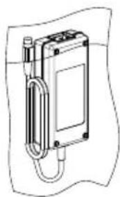
natural_image
Technical line drawing of a mechanical device with a curved arm and housing (no text or symbols)Netzteil Netzkabel
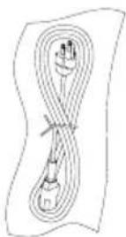
natural_image
Technical line drawing of an open industrial enclosure with internal components (no text or symbols)natural_image
Diagram of a robot's head and torso assembly with an upward arrow, showing internal components (no text or symbols)natural_image
Close-up of a hand holding a black cable with metallic connector (no visible text or symbols)
natural_image
Hand inserting a black cable into a white electronic device casing (no text or symbols visible)natural_image
Technical line drawing of two open battery compartments with a circular component on the left (no text or symbols)natural_image
Technical line drawing of an open industrial machine with internal components and a labeled section 'A' (no text or symbols beyond the label)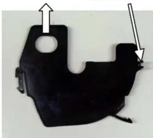
natural_image
Black metal mechanical component with two arrows pointing to features (no text or symbols)Abstandshalter
natural_image
Close-up of a mechanical component with internal structure and mounting holes (no visible text or symbols)70 mm Einstellnut
Papierrollenbreite 70 mm
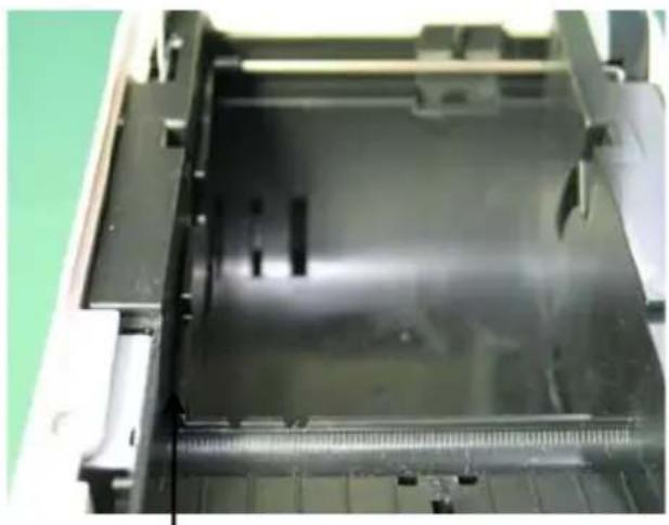
natural_image
Close-up of a mechanical component with internal structural details and a ruler for scale (no visible text or symbols)80 mm Einstellnut
Papierrollenbreite 80 mm
natural_image
Close-up of a hand holding a black plastic component with directional arrows indicating motion (no text or symbols visible)natural_image
Close-up of a hand inserting a black plastic component into a black plastic housing, with arrows indicating the process (no text or symbols visible)natural_image
Technical line drawing of a mechanical device with an open lid and internal components, showing no text or symbols.natural_image
Line drawing of an open industrial machine with a cross symbol indicating cancellation (no text or labels present)natural_image
Technical line drawing of a mechanical device with open lid and internal rollers (no text or symbols)natural_image
Two abstract circular patterns: one with a curved line and the other with a cross, both without any text or symbols.natural_image
Close-up of a white plastic panel with black insulation and a black inner component, against a green background (no text or symbols visible)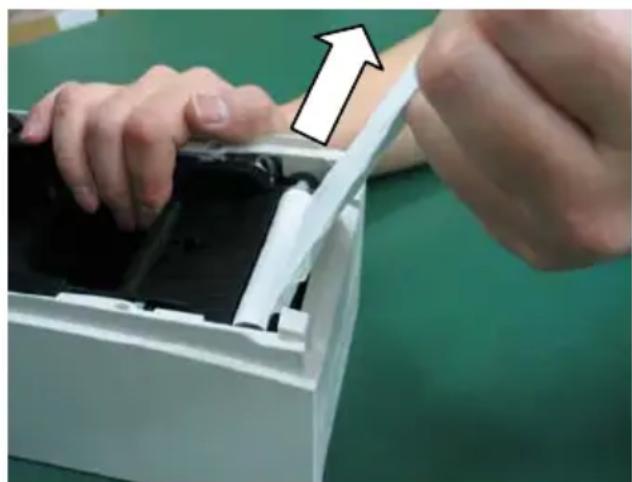
natural_image
Close-up of hands installing or adjusting a device into a white plastic container (no visible text or symbols)natural_image
Close-up of a hand opening a white plastic electronic device with black internal components (no visible text or symbols)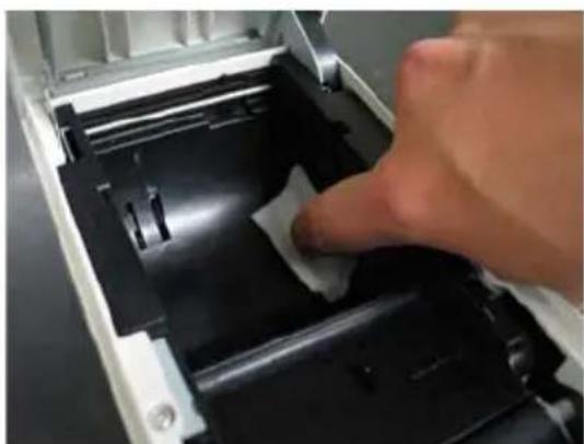
natural_image
Close-up of a hand pressing down on a mechanical component with a white paper clip (no visible text or symbols)flowchart
graph TD
    A["CUTTER CLEANING"] --> B["1. Open Cover, and remove Roll Paper"]
    B --> C["2. Push FEED switch to move Cutter to the cleaning position"]
    C --> D["3. When cleaning is completed, set Roll Paper, and close Cover"]
    D --> E["Richtung der Papierzufuhr"]
natural_image
Close-up of a hand pressing down on a white plastic sheet inside a mechanical device (no text or symbols visible)Druckwalze
natural_image
Two screwdriver tools on a dark surface, one with a blue handle and the other with a black clip (no text or symbols visible)
flowchart
graph TD
    A["CUTTER CLEANING"] --> B["1. Open Cover, and remove Roll Paper"]
    A --> C["2. Push FEED switch to move Cutter to the cleaning position"]
    A --> D["3. When cleaning is completed, set Roll Paper, and close Cover"]
    E["Richtung der Papierzufuhr"] --> A
natural_image
Close-up of a mechanical component with a tool interacting with a textured surface (no visible text or symbols)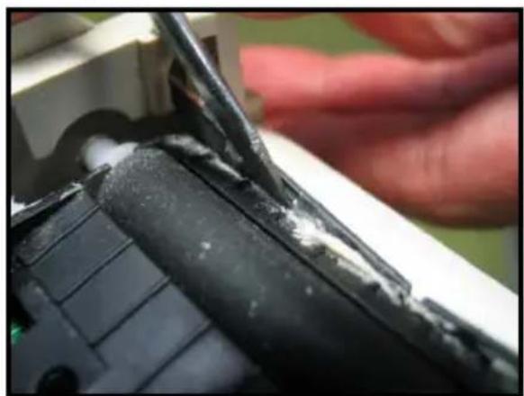
natural_image
Close-up of a hand using a power tool to repair a damaged black cylindrical object with white marks (no text or symbols visible)natural_image
Simple line drawing of a rectangular shape with internal grid lines (no text or symbols)(4) DIP-Schalter
BUSY CONDITION BUFFERFULL
RECEIVE ERROR ?PRINT
AUTO LF DISABLE
DSR(#6) RESET DISABLE
C-2. Hex Dump
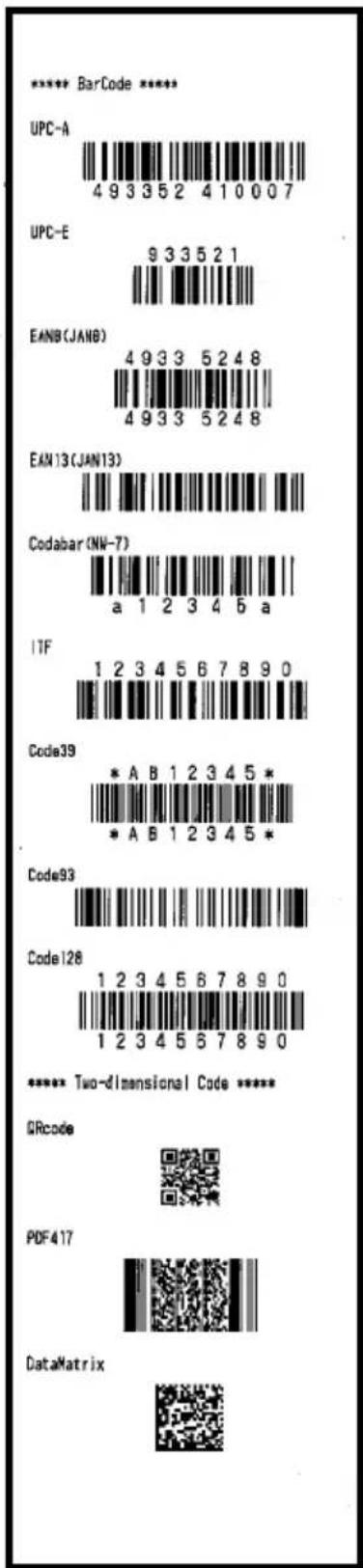
Oki Systems (UK) Ltd
Blays House
Wick Road
Egham
Surrey
TW20 0HJ
Tel: +44 (0) 1784 274300
Fax: +44 (0) 1784 274301
http://www.oki.co.uk
Oki Systems Ireland Limited
The Square Industrial Complex Tallaght
Dublin 24
Tel: +353 (0) 1 4049590
Fax: +353 (0)1 4049591
http://www.oki.ie
Oki Systems Ireland Limited - Northern Ireland
19 Ferndale Avenue
Glengormley
BT36 5AL
Northern Ireland
Tel: +44 (0) 7767 271447
Fax: +44 (0) 1 404 9520
http://www.oki.ie
Technical Support for all Ireland:
Tel: +353 1 4049570
Fax: +353 1 4049555
E-mail: tech.support@oki.ie
OKI Systems (Czech and Slovak), s.r.o.
Futurama Business Park -
Sokolovská 651/136A
186 00 Praha 8
Czech Republic
Tel: +420 224 890158
Fax:+420 22 232 6621
Website: www.oki.cz, www.oki.sk
Albania, Bosnia, Bulgaria, Croatia,
Cyprus, Estonia, Greece, Israel,
Latvia, Lithuania, Macedonia,
Romania, Serbia, Slovenia
CEE Export Group: OKI Systems (Poland) Ltd
ul. Domaniewska 42
02-672 Warsaw
Poland
Tel: +48 (0) 22 448 65 00
Fax: +48 (0) 22 448 65 0
E-mail: tech@oki.com.pl
Platinum Business Park II, 3rd Floor
ul. Domaniewska 42
02-672 Warsaw
Poland
Tel: +48 22 448 65 00
Fax: +48 22 448 65 01
Website: www.oki.com.pl
E-mail: oki@oki.com.pl
Hotline: 0800 120066
E-mail: tech@oki.com.pl
OKI Systems Rus, LLC (Russia)
Sector B, 3rd Floor, Svyatogor-4
Business Center10/4, Letnikovskaya
str.115114, Moscow
Tel: +7 495 276 5060
Fax: +7 495 258 6070
e-mail: info@oki.ru
Website: www.oki.ru
Technical support:
Tel: +7 495 564 8421
e-mail: tech@oki.ru
Raisy Opkinoy Street,8
Building B, 2 ^nd Floor,
Kiev 02002
Ukraine
Tel: +380 44 537 5288
e-mail: event@oki.ua
Website: www.oki.ua
Oki Systems (Belgium)
Medialaan 24
1800 Vilvoorde
Helpdesk: 02-2574620
Fax: 02 2531848
Website: www.oki.be
OKI Systems (Danmark) a·s
Herstedøstervej 27
2620 Albertslund
Danmark
Oki Systems (Norway) AS
Tevlingveien 23
N-1081 Oslo
Tel: +47 (0) 63 89 36 00
Telefax: +47 (0) 63 89 36 01
Website: www.oki.no
Var vänlig kontakta din
Oki Systems (Sweden) AB
Borgafjordsgatan 7
Box 1193
164 26 Kista
Tel. +46 (0) 8 634 37 00
e-mail: info@oki.se
Website: www.oki.se
2000 Bishops Gate Blvd.
http://WWW.OKIPRINTINGSOLUTIONS.COM
http://my.okidata.com
Oki Data Americas Inc.(Canada • Canadá)
4140B Sladeview Crescent Unit 7 & 8
Mississauga, Ontario
Canada L5L 6A1
Tél: 1-905-608-5000
Téléc: 1-905-608-5040
http://WWW.OKIPRINTINGSOLUTIONS.COM
Oki Data Americas Inc.(América Latina (OTRO))
2000 Bishops Gate Blvd.
HTTP://www.okiprintingsolutions.com
Argentina/ Chile/ Paraguay/ Perú/ Uruguay
Oki Data Americas, Inc.
Sucursal Argentina
Ugarte 3610 Piso 4°(1605) Olivos
Buenos Aires, Argentina
TEL: +54 11 5288 7500
Fax: +54 11 5288 7599
Colombia/ Ecuador/ Venezuela/ Centroamérica y Caribe Oki Data Americas, Inc.
Sucursal Colombia
1168/81-82 Lumpini Tower, 27th Floor Rama IV Road
Tungmahamek, Sathorn
Bangkok 10120
Tel: (662) 679 9235
Fax: (662) 679 9243/245
http://www.okisysthai.com
Oki Data(Australia) Pty Ltd.
Level1 67 Epping Road, Macquare Park
NSW 2113, Australia
Tel: +61 2 8071 0000
(Support Tel: 1800 807 472)
Fax: +61 2 8071 0010
http://www.oki.com.au
OKI Data New Zealand
8 Antares Place Rosedale,
Auckland, 0632 New Zealand
Tel: (64) 9 477 0500
Fax: (64) 9 477 0549
http://www.oki.co.nz/
Oki Data(S) P Ltd. Malaysia Rep Office
Suite 21.03, 21st Floor Menara IGB, Mid Valley City,
Lingkaran Syed Pura 59200,
Kuala Lumpur, Malaysia
Tel: (60) 3 2287 1177
Fax: (60) 3 2287 1166
PT390
OKI
Guía del usuario
PREFACIO
© 2011 Oki Data Corporation
Oki Data Corporation,
4-11-22 Shibaura, Minato-ku,
Tokio 108-8551,
Japón
Following information is only for the province of Buenos Aires in Argentine:
natural_image
Simple geometric diagram with concentric circles and a diagonal line inside a diamond shape (no text or symbols)MANUAL
DRIVER DE LA IMPRESORA
PROGRAMA DE UTILIDAD

natural_image
Simple geometric diamond shape with no text or symbolsnatural_image
Simple geometric diamond shape with no text or symbolsnatural_image
Technical line drawing of a mechanical device with no visible text or symbolsnatural_image
Simple line drawing of a rope or rope structure with no text, numbers, or symbolsnatural_image
Diagram of a mechanical device with an upward arrow and internal components (no text or symbols)natural_image
Close-up of a hand holding a black cable with metallic connector (no visible text or symbols)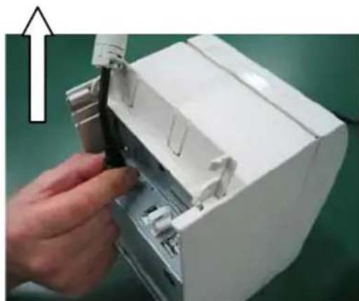
natural_image
Hand inserting a component into a white electronic device casing (no visible text or symbols)natural_image
Technical line drawing of two open electrical switchgear boxes with a circular component and a cross symbol (no text or labels)natural_image
Close-up of a metallic mechanical component with internal structural details and a threaded rod (no visible text or symbols)Ranura de ajuste de 58 mm
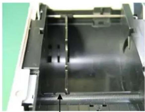
natural_image
Close-up of a mechanical component with a black plastic sheet and a white housing, showing internal structure and a small arrow pointing to a feature (no text or symbols visible)Ranura de ajuste de 60 mm
natural_image
Close-up of a mechanical component with internal structure and measurement markings (no visible text or symbols)Ranura de ajuste de 70 mm
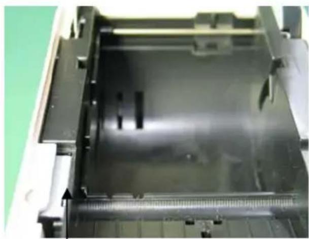
natural_image
Close-up of a mechanical component with internal structure and mounting holes (no visible text or symbols)Ranura de ajuste de 80 mm
natural_image
Technical line drawing of a mechanical device with an open lid and internal components, showing no text or symbols.natural_image
Technical line drawing of a mechanical device with an open lid and internal components, no text or symbols present.natural_image
Technical line drawing of an open industrial machine with a cross symbol indicating cancellation (no text or labels present)natural_image
Two abstract circular patterns with a circle and an X symbol, no text or labels present.natural_image
Close-up of a white plastic panel with black insulation and a black cover, against a green background (no text or symbols visible)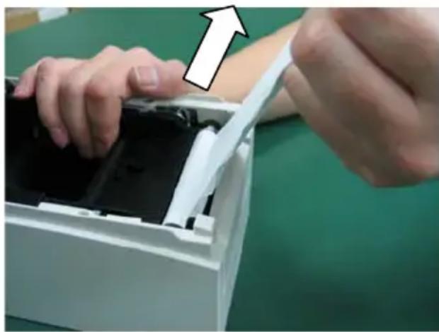
natural_image
Close-up of hands installing or adjusting a device into a white plastic container (no visible text or symbols)natural_image
Two types of screwdriver tools on a dark surface: one with a metallic tip and the other with a flat blade and black clip (no text or symbols visible)
flowchart
graph TD
    A["CUTTER CLEANING"] --> B["1. Open Cover, and remove Roll Paper."]
    B --> C["2. Push FEED switch to move Cutter to the cleaning position."]
    C --> D["3. When cleaning is completed, set Roll Paper, and close Cover"]
    D --> E["Downward arrow"]
natural_image
Simple line drawing of a rectangular shape with internal vertical lines (no text or symbols)(4) Interruptores DIP
BUSY CONDITION BUFFERFULL
RECEIVE ERROR ?PRINT
AUTO LF DISABLE
DSR(#6) RESET DISABLE
:
C-2. Hex Dump (volcado hexadecimal)
Patrón "Coupon" (80 mm)

Patrón "Barcode" (80 mm)
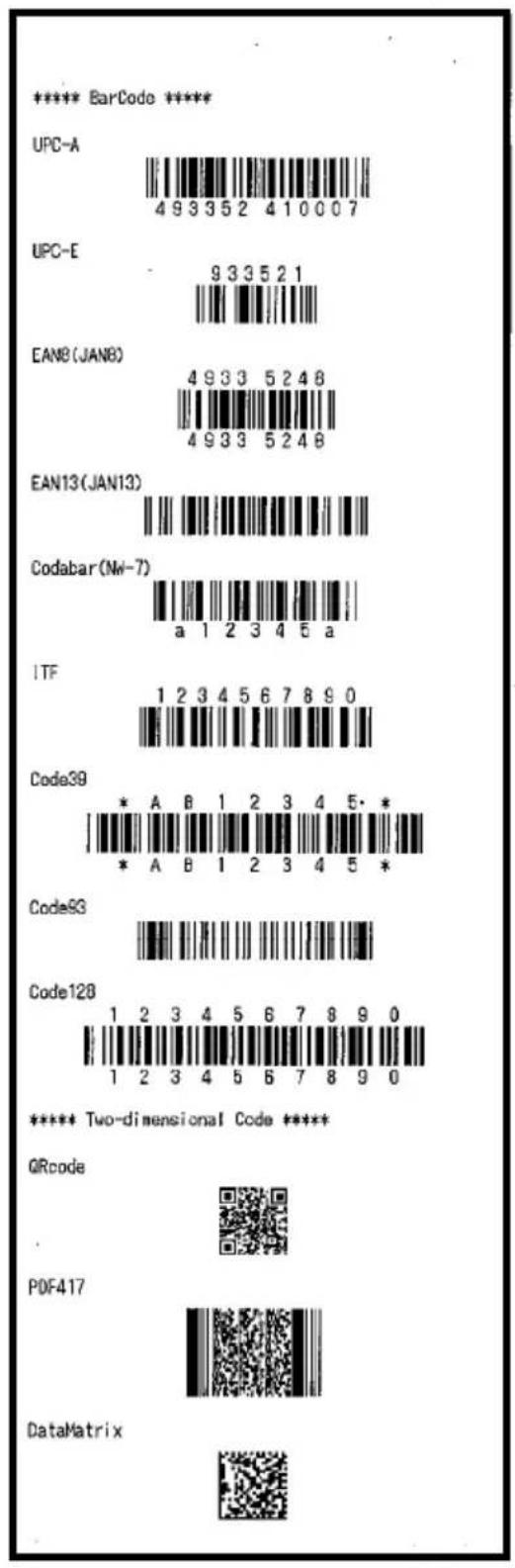
Patrón "Receipt" (58 mm)

Patrón "Barcode" (58 mm)
Patrón "Coupon" (58 mm)

Oki Systems (UK) Ltd
Blays House
Wick Road
Egham
Surrey
TW20 0HJ
Tel: +44 (0) 1784 274300
Fax: +44 (0) 1784 274301
http://www.oki.co.uk
Oki Systems Ireland Limited
The Square Industrial Complex Tallaght
Dublin 24
Tel: +353 (0) 1 4049590
Fax: +353 (0)1 4049591
http://www.oki.ie
Oki Systems Ireland Limited - Northern Ireland
19 Ferndale Avenue
Glengormley
BT36 5AL
Northern Ireland
Tel: +44 (0) 7767 271447
Fax: +44 (0) 1 404 9520
http://www.oki.ie
Technical Support for all Ireland:
Tel: +353 1 4049570
Fax: +353 1 4049555
E-mail: tech.support@oki.ie
OKI Systems (Czech and Slovak), s.r.o.
Futurama Business Park - Sokolovská 651/136A
186 00 Praha 8
Czech Republic
Tel: +420 224 890158
Fax:+420 22 232 6621
Website: www.oki.cz, www.oki.sk
Albania, Bosnia, Bulgaria, Croatia,
Cyprus, Estonia, Greece, Israel,
Latvia, Lithuania, Macedonia,
Romania, Serbia, Slovenia
CEE Export Group: OKI Systems (Poland) Ltd
ul. Domaniewska 42
02-672 Warsaw
Poland
Tel: +48 (0) 22 448 65 00
Fax: +48 (0) 22 448 65 0
E-mail: tech@oki.com.pl
Platinum Business Park II, 3rd Floor
ul. Domaniewska 42
02-672 Warsaw
Poland
Tel: +48 22 448 65 00
Fax: +48 22 448 65 01
Website: www.oki.com.pl
E-mail: oki@oki.com.pl
Hotline: 0800 120066
E-mail: tech@oki.com.pl
OKI Systems Rus, LLC (Russia)
Sector B, 3rd Floor, Svyatogor-4
Business Center10/4, Letnikovskaya
str.115114, Moscow
Tel: +7 495 276 5060
Fax: +7 495 258 6070
e-mail: info@oki.ru
Website: www.oki.ru
Technical support:
Tel: +7 495 564 8421
e-mail: tech@oki.ru
Raisy Opkinoy Street,8
Building B, 2 ^nd Floor,
Kiev 02002
Ukraine
Tel: +380 44 537 5288
e-mail: event@oki.ua
Website: www.oki.ua
Oki Systems (Belgium)
Medialaan 24
1800 Vilvoorde
Helpdesk: 02-2574620
Fax: 02 2531848
Website: www.oki.be
OKI Systems (Danmark) a·s
Herstedøstervej 27
2620 Albertslund
Danmark
Oki Systems (Norway) AS
Tevlingveien 23
N-1081 Oslo
Tel: +47 (0) 63 89 36 00
Telefax: +47 (0) 63 89 36 01
Website: www.oki.no
Var vänlig kontakta din
Oki Systems (Sweden) AB
Borgafjordsgatan 7
Box 1193
164 26 Kista
Tel. +46 (0) 8 634 37 00
e-mail: info@oki.se
Website: www.oki.se
2000 Bishops Gate Blvd.
http://WWW.OKIPRINTINGSOLUTIONS.COM
http://my.okidata.com
Oki Data Americas Inc.(Canada • Canadá)
4140B Sladeview Crescent Unit 7 & 8
Mississauga, Ontario
Canada L5L 6A1
Tél: 1-905-608-5000
Téléc: 1-905-608-5040
http://WWW.OKIPRINTINGSOLUTIONS.COM
Oki Data Americas Inc.(América Latina (OTRO))
2000 Bishops Gate Blvd.
HTTP://www.okiprintingsolutions.com
Argentina/ Chile/ Paraguay/ Perú/ Uruguay
Oki Data Americas, Inc.
Sucursal Argentina
Ugarte 3610 Piso 4°(1605) Olivos
Buenos Aires, Argentina
TEL: +54 11 5288 7500
Fax: +54 11 5288 7599
Colombia/ Ecuador/ Venezuela/ Centroamérica y Caribe Oki Data Americas, Inc.
Sucursal Colombia
1168/81-82 Lumpini Tower,
27th Floor Rama IV Road
Tungmahamek, Sathorn
Bangkok 10120
Tel: (662) 679 9235
Fax: (662) 679 9243/245
http://www.okisysthai.com
Oki Data(Australia) Pty Ltd.
Level1 67 Epping Road, Macquare Park
NSW 2113, Australia
Tel: +61 2 8071 0000
(Support Tel: 1800 807 472)
Fax: +61 2 8071 0010
http://www.oki.com.au
OKI Data New Zealand
8 Antares Place Rosedale,
Auckland, 0632 New Zealand
Tel: (64) 9 477 0500
Fax: (64) 9 477 0549
http://www.oki.co.nz/
Oki Data(S) P Ltd. Malaysia Rep Office
Suite 21.03, 21st Floor Menara IGB, Mid Valley City,
Lingkaran Syed Pura 59200,
Kuala Lumpur, Malaysia
Tel: (60) 3 2287 1177
Fax: (60) 3 2287 1166
PT390
OKI
Manual do utilizador
PREFÁCIO
© 2011 Oki Data Corporation
Oki Data Corporation,
4-11-22 Shibaura, Minato-ku,
Tóquio 108-8551,
Japão
natural_image
Simple geometric diagram with concentric circles and a diagonal line inside a diamond shape (no text or symbols)MANUAL
DRIVER DE IMPRESSORA
UTILITÁRIO DE
SOFTWARE

natural_image
Simple geometric diamond shape outline with no text or symbolsFolha de instrução

natural_image
Simple geometric diamond shape with no text or symbolsnatural_image
Technical line drawing of a mechanical device with a coiled cable and housing (no text or symbols)Adaptador CA Cabo de força
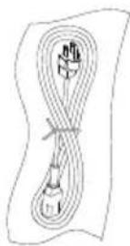
natural_image
Simple line drawing of a rope tied with a string, no text or symbols presentnatural_image
Diagram of a mechanical device with an upward arrow and internal components (no text or symbols)natural_image
Technical line drawing of two open electrical switch compartments with a circular component on the left (no text or symbols)natural_image
Close-up of a hand holding a black plastic component with directional arrows indicating rotation (no text or symbols visible)natural_image
Close-up of a hand inserting a black plastic component into a black plastic housing (no text or symbols visible)natural_image
Technical line drawing of a mechanical device with an open lid and internal components, showing no text or symbols.natural_image
Technical line drawing of a mechanical device with an open lid and internal components, no text or symbols present.natural_image
Technical line drawing of a mechanical device with open lid and paper rolls, no text or symbols presentnatural_image
Close-up of a white plastic panel with black insulation and black connectors, no visible text or symbols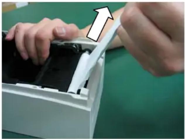
natural_image
Close-up of hands installing or adjusting a device into a white plastic container with black casing, no visible text or symbolsnatural_image
Hand placing a white plastic component into a white plastic housing (no text or symbols visible)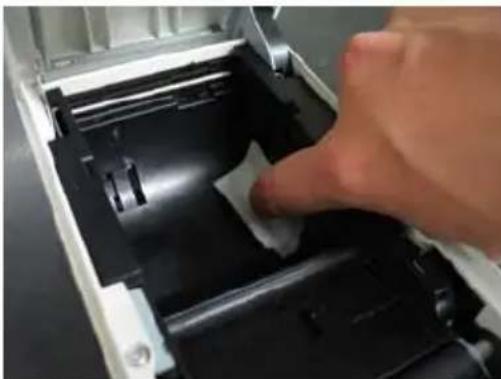
natural_image
Close-up of a hand pressing down on a mechanical component with a white paper clip (no visible text or symbols)8-2. Limpar o cilindro de impressora
flowchart
graph TD
    A["PLATEN ROLLER CLEANING MODE"] --> B["1. Open Cover, and remove Roll Paper"]
    A --> C["2. Push FEED switch to move Platen Roller to the cleaning position"]
    A --> D["3. When cleaning is completed, set Roll Paper, and close Cover"]
    E["Direção de alimentação do papel"] --> A
natural_image
Close-up of a hand pressing down on a white plastic component, showing a curved arrow (no text or symbols visible)natural_image
Two screwdriver tools placed on a dark surface, one with a blue handle and the other with a white handle (no text or symbols visible)
flowchart
graph TD
    A["CUTTER CLEANING"] --> B["1. Open Cover, and remove Roll Paper"]
    B --> C["2. Push FEED switch to move Cutter to the cleaning position"]
    C --> D["3. When cleaning is completed, set Roll Paper, and close Cover"]
    D --> E["→"]
    style A fill:#f9f,stroke:#333
    style B fill:#ccf,stroke:#333
    style C fill:#cfc,stroke:#333
    style D fill:#fcc,stroke:#333
natural_image
Simple line drawing of a rectangular shape with internal divisions and tick marks (no text or symbols)(4) Chaves DIP
BUSY CONDITION BUFFERFULL
RECEIVE ERROR ?PRINT
AUTO LF DISABLE
DSR(#6) RESET DISABLE
:
C-2. Dump HEX
83mm/53 colunas -> Padrão 80mm
80mm/48 colunas -> Padrão 80mm
80mm/42 colunas -> Padrão 80mm
60mm/36 colunas -> Padrão 58mm
58mm/35 colunas -> Padrão 58mm
58mm/32 colunas -> Padrão 58mm
Padrão "Cupom" (58 mm)

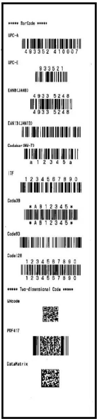
Oki Systems (UK) Ltd
Blays House
Wick Road
Egham
Surrey
TW20 0HJ
Tel: +44 (0) 1784 274300
Fax: +44 (0) 1784 274301
http://www.oki.co.uk
Oki Systems Ireland Limited
The Square Industrial Complex Tallaght
Dublin 24
Tel: +353 (0) 1 4049590
Fax: +353 (0)1 4049591
http://www.oki.ie
Oki Systems Ireland Limited - Northern Ireland
19 Ferndale Avenue
Glengormley
BT36 5AL
Northern Ireland
Tel: +44 (0) 7767 271447
Fax: +44 (0) 1 404 9520
http://www.oki.ie
Technical Support for all Ireland:
Tel: +353 1 4049570
Fax: +353 1 4049555
E-mail: tech.support@oki.ie
OKI Systems (Czech and Slovak), s.r.o.
Futurama Business Park - Sokolovská 651/136A
186 00 Praha 8
Czech Republic
Tel: +420 224 890158
Fax:+420 22 232 6621
Website: www.oki.cz, www.oki.sk
Albania, Bosnia, Bulgaria, Croatia,
Cyprus, Estonia, Greece, Israel,
Latvia, Lithuania, Macedonia,
Romania, Serbia, Slovenia
CEE Export Group: OKI Systems (Poland) Ltd
ul. Domaniewska 42
02-672 Warsaw
Poland
Tel: +48 (0) 22 448 65 00
Fax: +48 (0) 22 448 65 0
E-mail: tech@oki.com.pl
Platinum Business Park II, 3rd Floor
ul. Domaniewska 42
02-672 Warsaw
Poland
Tel: +48 22 448 65 00
Fax: +48 22 448 65 01
Website: www.oki.com.pl
E-mail: oki@oki.com.pl
Hotline: 0800 120066
E-mail: tech@oki.com.pl
OKI Systems Rus, LLC (Russia)
Sector B, 3rd Floor, Svyatogor-4
Business Center10/4, Letnikovskaya
str.115114, Moscow
Tel: +7 495 276 5060
Fax: +7 495 258 6070
e-mail: info@oki.ru
Website: www.oki.ru
Technical support:
Tel: +7 495 564 8421
e-mail: tech@oki.ru
Raisy Opkinoy Street,8
Building B, 2 ^nd Floor,
Kiev 02002
Ukraine
Tel: +380 44 537 5288
e-mail: event@oki.ua
Website: www.oki.ua
Oki Systems (Belgium)
Medialaan 24
1800 Vilvoorde
Helpdesk: 02-2574620
Fax: 02 2531848
Website: www.oki.be
OKI Systems (Danmark) a·s
Herstedøstervej 27
2620 Albertslund
Danmark
Oki Systems (Norway) AS
Tevlingveien 23
N-1081 Oslo
Tel: +47 (0) 63 89 36 00
Telefax: +47 (0) 63 89 36 01
Website: www.oki.no
Var vänlig kontakta din
Oki Systems (Sweden) AB
Borgafjordsgatan 7
Box 1193
164 26 Kista
Tel. +46 (0) 8 634 37 00
e-mail: info@oki.se
Website: www.oki.se
2000 Bishops Gate Blvd.
http://WWW.OKIPRINTINGSOLUTIONS.COM
http://my.okidata.com
Oki Data Americas Inc.(Canada • Canadá)
4140B Sladeview Crescent Unit 7 & 8
Mississauga, Ontario
Canada L5L 6A1
Tél: 1-905-608-5000
Téléc: 1-905-608-5040
http://WWW.OKIPRINTINGSOLUTIONS.COM
Oki Data Americas Inc.(América Latina (OTRO))
2000 Bishops Gate Blvd.
HTTP://www.okiprintingsolutions.com
Argentina/ Chile/ Paraguay/ Perú/ Uruguay
Oki Data Americas, Inc.
Sucursal Argentina
Ugarte 3610 Piso 4°(1605) Olivos
Buenos Aires, Argentina
TEL: +54 11 5288 7500
Fax: +54 11 5288 7599
Colombia/ Ecuador/ Venezuela/ Centroamérica y Caribe Oki Data Americas, Inc.
Sucursal Colombia
1168/81-82 Lumpini Tower,
27th Floor Rama IV Road
Tungmahamek, Sathorn
Bangkok 10120
Tel: (662) 679 9235
Fax: (662) 679 9243/245
http://www.okisysthai.com
Oki Data(Australia) Pty Ltd.
Level1 67 Epping Road, Macquare Park
NSW 2113, Australia
Tel: +61 2 8071 0000
(Support Tel: 1800 807 472)
Fax: +61 2 8071 0010
http://www.oki.com.au
OKI Data New Zealand
8 Antares Place Rosedale,
Auckland, 0632 New Zealand
Tel: (64) 9 477 0500
Fax: (64) 9 477 0549
http://www.oki.co.nz/
Oki Data(S) P Ltd. Malaysia Rep Office
Suite 21.03, 21st Floor Menara IGB, Mid Valley City,
Lingkaran Syed Pura 59200,
Kuala Lumpur, Malaysia
Tel: (60) 3 2287 1177
Fax: (60) 3 2287 1166
Oki Data Corporation
4-11-22 Shibaura, Minato-ku, Tokyo
108-8551, Japan
www.oki.com/printing

- MANUFACTURER
- IMPORTER TO THE EU/AUTHORISED REPRESENTATIVE
- ENVIRONMENTAL INFORMATION
- Description of Safety symbols displayed on the equipment
- TABLE OF CONTENTS
- Appearance and Names of Components
- Appended goods
- AC Adapter and Thermal Roll Paper
- 2-1. AC adapter
- 2-2. Paper specification (Thermal paper)
- Preparations
- 3-1. Connecting Interface Cable
- For a unit with parallel interfaces
- For a unit with Dual interface
- For a unit with LAN interface
- 3-2. Connecting the drawer kick cable
- 3-3. Connecting the AC Adapter
- 3-4. Disconnecting the AC Adapter
- 3-5. Turning on the Power
- 3-6. Installing the Printer Software
- Inserting Paper for Printing
- 4-1. Replacing paper
- How to remove the separator
- How to attach the separator
- Control Panel
- 5-1. Control Panel
- 5-2. Error Indications
- Preventing and Clearing Paper Jams
- 6-1. Preventing Paper Jams
- 6-2. Clearing a Paper Jam
- Troubleshooting
- Regular Cleaning
- 8-1. Cleaning the Paper Holder and Paper Transport
- 8-2. Cleaning the Platen Roller
- 8-3. Cleaning the Thermal Head
- 8-4. Cleaning the Cutter Blade and Frame
- Notes on Use
- Notes on using the cutter
- Notes on printing of barcodes and two-dimensional codes
- Notes on using the printer through the USB interface
- Note on installation
- Note on the modular connector
- Note on using the printer in special mode
- Appendix A: Specifications
- A-1.General Specifications
- A-2.Cutter Specifications
- A-3. Paper Supply Specifications
- A-4. Interface Specifications
- A-5.Environment Specifications
- A-6. Specifications of Reliability
- Printer life
- Head
- Cutter
- Appendix B: Interface
- B-1.Parallel Interface
- Forward channel
- B-2.Dual Interface
- B-3.LAN Interface
- Initialization of settings
- Self test print of settings
- B-4. Drawer Kick Connector
- B-5. Specifications of Power Supply
- Appendix C: Special Modes
- C-1.Test Printing
- Sample test printout
- C-2.Hex Dump
- C-3. Setting Up the Printer
- Select "130%" as your option.
- Select "5" as your option.
- C-4.Setup Items
- C-5.Sample Print
- Printed result of sample printings
- Oki Systems (UK) Ltd
- Oki Systems Ireland Limited
- Oki Systems Ireland Limited - Northern Ireland
- OKI Systems (Czech and Slovak), s.r.o.
- CEE Export Group: OKI Systems (Poland) Ltd
- OKI Systems Rus, LLC (Russia)
- Oki Systems (Belgium)
- OKI Systems (Danmark) a·s
- Oki Systems (Norway) AS
- Oki Systems (Sweden) AB
- Oki Data Americas Inc.(Canada • Canadá)
- Oki Data Americas Inc.(América Latina (OTRO))
- Argentina/ Chile/ Paraguay/ Perú/ Uruguay
- Oki Data Americas, Inc.
- Colombia/ Ecuador/ Venezuela/ Centroamérica y Caribe Oki Data Americas, Inc.
- Oki Data(Australia) Pty Ltd.
- OKI Data New Zealand
- Oki Data(S) P Ltd. Malaysia Rep Office
- PT390
- OKI
- C-2. Vidage hexadécimal
- Manuale d'uso
- PREFAZIONE
- Benutzerhandbuch
- VORWORT
- DIP-Schalter
- C-2. Hex Dump
- Guía del usuario
- PREFACIO
- Interruptores DIP
- C-2. Hex Dump (volcado hexadecimal)
- Manual do utilizador
- PREFÁCIO
- 8-2. Limpar o cilindro de impressora
- C-2. Dump HEX
- Oki Data Corporation
Brand : OKI
Model : PT390
Category : Printer