B150MDVS R2.0 - Motherboard ASROCK - Free user manual and instructions
Find the device manual for free B150MDVS R2.0 ASROCK in PDF.
Download the instructions for your Motherboard in PDF format for free! Find your manual B150MDVS R2.0 - ASROCK and take your electronic device back in hand. On this page are published all the documents necessary for the use of your device. B150MDVS R2.0 by ASROCK.
USER MANUAL B150MDVS R2.0 ASROCK
Version 1.0 Published April 2016 Copyright©2016 ASRock INC. All rights reserved. Copyright Notice: No part of this documentation may be reproduced, transcribed, transmitted, or translated in any language, in any form or by any means, except duplication of documentation by the purchaser for backup purpose, without written consent of ASRock Inc. Products and corporate names appearing in this documentation may or may not be registered trademarks or copyrights of their respective companies, and are used only for identication or explanation and to the owners’ benet, without intent to infringe. Disclaimer: Specications and information contained in this documentation are furnished for informational use only and subject to change without notice, and should not be constructed as a commitment by ASRock. ASRock assumes no responsibility for any errors or omissions that may appear in this documentation. With respect to the contents of this documentation, ASRock does not provide warranty of any kind, either expressed or implied, including but not limited to the implied warranties or conditions of merchantability or tness for a particular purpose. In no event shall ASRock, its directors, ocers, employees, or agents be liable for any indirect, special, incidental, or consequential damages (including damages for loss of prots, loss of business, loss of data, interruption of business and the like), even if ASRock has been advised of the possibility of such damages arising from any defect or error in the documentation or product. is device complies with Part 15 of the FCC Rules. Operation is subject to the following two conditions: (1) this device may not cause harmful interference, and (2) this device must accept any interference received, including interference that may cause undesired operation.
CALIFORNIA, USA ONLY
e Lithium battery adopted on this motherboard contains Perchlorate, a toxic substance controlled in Perchlorate Best Management Practices (BMP) regulations passed by the California Legislature. When you discard the Lithium battery in California, USA, please follow the related regulations in advance. “Perchlorate Material-special handling may apply, see www.dtsc.ca.gov/hazardouswaste/ perchlorate” ASRock Website: http://www.asrock.comAUSTRALIA ONLY Our goods come with guarantees that cannot be excluded under the Australian Consumer Law. You are entitled to a replacement or refund for a major failure and compensation for any other reasonably foreseeable loss or damage caused by our goods. You are also entitled to have the goods repaired or replaced if the goods fail to be of acceptable quality and the failure does not amount to a major failure. If you require assistance please call ASRock Tel : +886-2-28965588 ext.123 (Standard International call charges apply)1 English
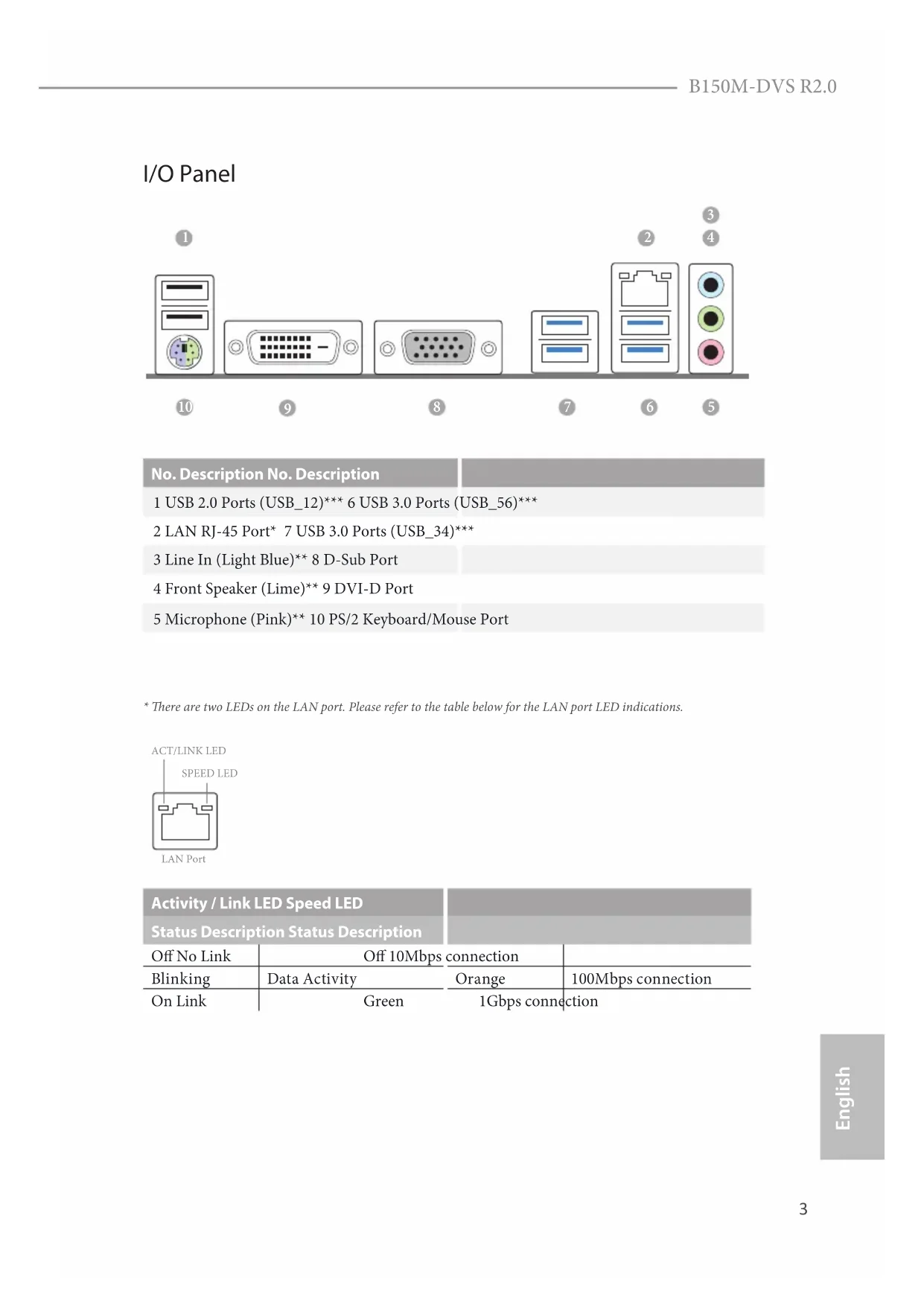
I/O Panel No. Description No. Description 1 USB 2.0 Ports (USB_12)*** 6 USB 3.0 Ports (USB_56)*** 2 LAN RJ-45 Port* 7 USB 3.0 Ports (USB_34)*** 3 Line In (Light Blue)** 8 D-Sub Port 4 Front Speaker (Lime)** 9 DVI-D Port 5 Microphone (Pink)** 10 PS/2 Keyboard/Mouse Port
- ere are two LEDs on the LAN port. Please refer to the table below for the LAN port LED indications. Activity / Link LED Speed LED Status Description Status Description O No Link O 10Mbps connection Blinking Data Activity Orange 100Mbps connection On Link Green 1Gbps connection ACT/LINK LEDSPEED LEDLAN Port
English ** To congure 7.1 CH HD Audio, it is required to use an HD front panel audio module and enable the multi- channel audio feature through the audio driver. Please set Speaker Conguration to “7.1 Speaker”in the Realtek HD Audio Manager. Function of the Audio Ports in 7.1-channel Conguration: Port Function Light Blue (Rear panel) Rear Speaker Out Lime (Rear panel) Front Speaker Out Pink (Rear panel) Central /Subwoofer Speaker Out Lime (Front panel) Side Speaker Out *** ACPI wake-up function is supported on the rear USB ports only.5 English
1 Introduction ank you for purchasing ASRock B150M-DVS R2.0 motherboard, a reliable motherboard produced under ASRock’s consistently stringent quality control. It delivers excellent performance with robust design conforming to ASRock’s commitment to quality and endurance.
1 x I/O Panel Shield Because the motherboard specications and the BIOS soware might be updated, the content of this documentation will be subject to change without notice. In case any modications of this documentation occur, the updated version will be available on ASRock’s website without further notice. If you require technical support related to this motherboard, please visit our website for specic information about the model you are using. You may nd the latest VGA cards and CPU support list on ASRock’s website as well. ASRock website http://www.asrock.com.6 English
Solid Capacitor design CPU
Supports CPU up to 91W
5 Power Phase design
Supports Intel® Turbo Boost 2.0 Technology Chipset
Supports Intel® Small Business Basics Memory
Dual Channel DDR4 Memory Technology
Supports DDR4 2133 non-ECC, un-buered memory
Supports ECC UDIMM memory modules (operate in non- ECC mode)
Max. capacity of system memory: 32GB
- Supports NVMe SSD as boot disks
Intel® HD Graphics Built-in Visuals and the VGA outputs can be supported only with processors which are GPU integrated.
Supports Intel® HD Graphics Built-in Visuals : Intel® Quick Sync Video with AVC, MVC (S3D) and MPEG-2 Full HW Encode1, Intel® InTru
Max. shared memory 1024MB
- e size of maximum shared memory may vary from dierent operating systems.7 English
Dual graphics output: Support DVI-D and D-Sub ports by independent display controllers
Supports DVI-D with max. resolution up to 1920x1200 @ 60Hz
Supports D-Sub with max. resolution up to 1920x1200 @ 60Hz
Supports Accelerated Media Codecs: HEVC, VP8, VP9
Supports HDCP with DVI-D Port
Supports Full HD 1080p Blu-ray (BD) playback with DVI-D Port Audio
- To congure 7.1 CH HD Audio, it is required to use an HD front panel audio module and enable the multi-channel audio feature through the audio driver.
Supports Surge Protection (ASRock Full Spike Protection)
Supports Wake-On-LAN
Supports Lightning/ESD Protection (ASRock Full Spike Protection)
Supports LAN Cable Detection
Supports PXE Rear Panel I/O
2 x USB 2.0 Ports (Supports ESD Protection (ASRock Full Spike Protection))*
4 x USB 3.0 Ports (Supports ESD Protection (ASRock Full Spike Protection))*
- ACPI wake-up function is supported on the rear USB ports only.
1 x RJ-45 LAN Port with LED (ACT/LINK LED and SPEED LED)
HD Audio Jacks: Line in / Front Speaker / Microphone8 English Storage
6 x SATA3 6.0 Gb/s Connectors, support NCQ, AHCI and Hot Plug Connector
1 x Chassis Intrusion and Speaker Header
1 x CPU Fan Connector (4-pin)
- e CPU Fan Connector supports the CPU fan of maximum 1A (12W) fan power.
1 x Front Panel Audio Connector
2 x USB 2.0 Headers (Support 4 USB 2.0 ports) (Supports ESD Protection (ASRock Full Spike Protection))
1 x USB 3.0 Header (Supports 2 USB 3.0 ports) (Supports ESD Protection (ASRock Full Spike Protection)) BIOS Feature
AMI UEFI Legal BIOS with multilingual GUI support
ACPI 5.0 Compliant wake up events
CPU, DRAM, PCH 1.0V, VCCIO Voltage Multi-adjustment Hardware Monitor
CPU/Chassis temperature sensing
CPU/Chassis Quiet Fan (Auto adjust chassis fan speed by CPU temperature)
CPU/Chassis Fan multi-speed control
Please realize that there is a certain risk involved with overclocking, including adjusting the setting in the BIOS, applying Untied Overclocking Technology, or using third-party overclocking tools. Overclocking may aect your system’s stability, or even cause damage to the components and devices of your system. It should be done at your own risk and expense. We are not responsible for possible damage caused by overclocking.
- For detailed product information, please visit our website: http://www.asrock.com
- To install Windows® 7 OS, a modied installation disk with xHCI drivers packed into the ISO le is required. Please refer to page 54 for more detailed instructions.
1.3 Onboard Headers and Connectors
System Panel Header (9-pin PANEL1) (see p.1, No. 12) Connect the power switch, reset switch and system status indicator on the chassis to this header according to the pin assignments below. Note the positive and negative pins before connecting the cables. GND
RESET#PWRBTN#PLED-PLED+
GND PWRBTN (Power Switch): Connect to the power switch on the chassis front panel. You may congure the way to turn o your system using the power switch. RESET (Reset Switch): Connect to the reset switch on the chassis front panel. Press the reset switch to restart the computer if the computer freezes and fails to perform a normal restart. PLED (System Power LED): Connect to the power status indicator on the chassis front panel. e LED is on when the system is operating. e LED keeps blinking when the system is in S1/S3 sleep state. e LED is o when the system is in S4 sleep state or powered o (S5). HDLED (Hard Drive Activity LED): Connect to the hard drive activity LED on the chassis front panel. e LED is on when the hard drive is reading or writing data. e front panel design may dier by chassis. A front panel module mainly consists of power switch, reset switch, power LED, hard drive activity LED, speaker and etc. When connecting your chassis front panel module to this header, make sure the wire assignments and the pin assignments are matched correctly. Onboard headers and connectors are NOT jumpers. Do NOT place jumper caps over these headers and connectors. Placing jumper caps over the headers and connectors will cause permanent damage to the motherboard.11 English
Chassis Intrusion and Speaker Header (7-pin SPK_CI1) (see p.1, No. 16) Please connect the chassis intrusion and the chassis speaker to this header. Serial ATA3 Connectors (SATA3_0: see p.1, No. 8) (SATA3_1: see p.1, No. 9) (SATA3_2: see p.1, No. 10) (SATA3_3: see p.1, No. 11) (SATA3_4: see p.1, No. 13) (SATA3_5: see p.1, No. 14) ese six SATA3 connectors support SATA data cables for internal storage devices with up to
6.0 Gb/s data transfer rate.
USB 2.0 Headers (9-pin USB_7_8) (see p.1, No. 17) (9-pin USB_9_10) (see p.1, No. 6) ere are two headers on this motherboard. Each USB 2.0 header can support two ports. USB 3.0 Header (19-pin USB_11_12) (see p.1, No. 5) Besides four USB 3.0 ports on the I/O panel, there is one header on this motherboard. Each USB
3.0 header can support
two ports. DUMMY GND GND
IntA_P1_D+ IntA_P1_D- GND IntA_P1_SSTX+ GND IntA_P1_SSTX-IntA_P1_SSRX+IntA_P1_SSRX-VbusVbus Vbus IntA_P0_SSRX-IntA_P0_SSRX+ GND IntA_P0_SSTX-IntA_P0_SSTX+ GND IntA_P0_D-IntA_P0_D+ SATA3_2 SATA3_3 SATA3_0 SATA3_1 SATA3_5 SATA3_412 English Front Panel Audio Header (9-pin HD_AUDIO1) (see p.1, No. 20) is header is for connecting audio devices to the front audio panel. Chassis Fan Connectors (4-pin CHA_FAN1) (see p.1, No. 21) (4-pin CHA_FAN2) (see p.1, No. 7) Please connect fan cables to the fan connector and match the black wire to the ground pin. CPU Fan Connector (4-pin CPU_FAN1) (see p.1, No. 2) is motherboard pro- vides a 4-Pin CPU fan (Quiet Fan) connector. If you plan to connect a 3-Pin CPU fan, please connect it to Pin 1-3. ATX Power Connector (24-pin ATXPWR1) (see p.1, No. 4) is motherboard pro- vides a 24-pin ATX power connector. To use a 20-pin ATX power supply, please plug it along Pin 1 and Pin
1. High Denition Audio supports Jack Sensing, but the panel wire on the chassis
must support HDA to function correctly. Please follow the instructions in our manual and chassis manual to install your system.
2. If you use an AC’97 audio panel, please install it to the front panel audio header by
the steps below: A. Connect Mic_IN (MIC) to MIC2_L. B. Connect Audio_R (RIN) to OUT2_R and Audio_L (LIN) to OUT2_L. C. Connect Ground (GND) to Ground (GND). D. MIC_RET and OUT_RET are for the HD audio panel only. You don’t need to connect them for the AC’97 audio panel. E. To activate the front mic, go to the “FrontMic” Tab in the Realtek Control panel and adjust “Recording Volume”. GND FAN_VOLTAGE_CO NTROLFAN_SPEE DFAN_SPEE D_CON TROL
ATX 12V Power Connector (8-pin ATX12V1) (see p.1, No. 1) is motherboard pro- vides an 8-pin ATX 12V power connector. To use a 4-pin ATX power supply, please plug it along Pin 1 and Pin 5. Serial Port Header (9-pin COM1) (see p.1, No. 19) is COM1 header supports a serial port module. TPM Header (17-pin TPMS1) (see p.1, No. 15) is connector supports Trusted Platform Module (TPM) system, which can securely store keys, digital certicates, passwords, and data. A TPM system also helps enhance network security, protects digital identities, and ensures platform integrity. Print Port Header (25-pin LPT1) (see p.1, No. 18) is is an interface for print port cable that allows convenient connection of printer devices.
CCTS#1RRTS#1DDSR#1DDTR#1RRXD1
GND TTXD1DDCD#1 RRI#1
S_ P WRDWN #SE R IRQ #
Supporta CPU no a 91 W
Supporta Wake-On-LAN
Supports Processadores Intel® 6
Microso® Windows® 10 64-bit/8.1 64-bit/7 32-bit/7 64-bit
English Enabling USB Ports for Windows® 7 Installation Intel® Braswell and Skylake has removed their support for the Enhanced Host Controller Interface (EHCI – USB2.0) and only kept the eXtensible Host Controller Interface (XHCI – USB3.0). Due to that fact that XHCI is not included in the Windows 7 inbox drivers, users may nd it dicult to install Windows 7 operating system because the USB ports on their motherboard won’t work. In order for the USB ports to function properly, please create a Windows® 7 installation disk with the Intel® USB 3.0 eXtensible Host Controller (xHCI) drivers packed into the ISO le. Requirements
USB 3.0 drivers (included in the ASRock Support CD or website)
Win7 USB Patcher (included in the ASRock Support CD or website) Scenarios You have an ODD and PS/2 ports: If there is an optical disc drive, PS/2 ports and PS/2 Keyboard or mouse on your computer, you can skip the instructions below and go ahead to install Windows® 7 OS. You only have an ODD (For Intel Skylake platforms only): If there is an optical disc drive but no PS/2 ports on your computer, please enable the “PS/2 Simulator” option in UEFI SETUP UTILITY > Advanced > USB Conguration, which allows the USB port to function as a PS/2 port, and then you can install the Windows® 7 OS. Please set PS/S Simulator back to disabled aer the installation. You’ve got nothing: If you do not have an optical disc drive, please nd another computer and follow the instructions below to create a new ISO le with the “Win7 USB Patcher”. en use the new patched Windows® 7 installation USB drive to install Windows® 7 OS.55 English
Instructions Step 1 Insert the Windows® 7 installation disk or USB drive to your system. Step 2 Extract the tool (Win7 USB Patcher) and launch it. Step 3 Select the “Win7 Folder” from Step1 by clicking the red circle as shown as the picture below. Step 4 Select the “USB Driver Folder” by clicking the red circle as shown as the picture below. If you are using ASRock’s Support CD for the USB 3.0 driver, please select your CD-ROM.56 English Step 5 Select where to save the ISO le by pressing the red circle as shown as the picture below. Step 6 If you want to burn the patched image to a CD, please check “Burn Image” and select “Target Device to Burn”. If not, the patched ISO image will be exported to the destination selected in Step5. en Press “Start” to proceed. Step 7 Now you are able to install Windows® 7 on Braswell or Skylake with the new burned CD. Or please use the patched ISO image to make an OS USB drive to install the OS.Contact Information If you need to contact ASRock or want to know more about ASRock, you’re welcome to visit ASRock’s website at http://www.asrock.com; or you may contact your dealer for further information. For technical questions, please submit a support request form at http://www.asrock.com/support/tsd.asp ASRock Incorporation 2F., No.37, Sec. 2, Jhongyang S. Rd., Beitou District, Taipei City 112, Taiwan (R.O.C.) ASRock EUROPE B.V. Bijsterhuizen 11-11 6546 AR Nijmegen e Netherlands Phone: +31-24-345-44-33 Fax: +31-24-345-44-38 ASRock America, Inc. 13848 Magnolia Ave, Chino, CA91710 U.S.A. Phone: +1-909-590-8308 Fax: +1-909-590-1026EC-Declaration of Conformity For the following equipment: Motherboard (Product Name) B150M-DVS R2.0 / ASRock (Model Designation / Trade Name) ASRock Incorporation (Manufacturer Name) 2F., No.37, Sec. 2, Jhongyang S. Rd., Beitou District, Taipei City 112, Taiwan (R.O.C.) (Manufacturer Address) is herewith conrmed to comply with the requirements set out in the Council Directive on the Approximation of the Laws of the Member States relating to Electromagnetic Compatibility Directive (2004/108/EC) and Safety Directive (2006/95/ EC), the following standards are applied:
EN 55024: 1998 + A1:2001 + A2:2003 IEC 61000-4-2: 2008; IEC 61000-4-3: 2010; IEC 61000-4-4: 2010; IEC 61000-4-5: 2005; IEC 61000-4-6: 2008; IEC 61000-4-8: 2009; IEC 61000-4-11: 2004;
e following manufacturer / importer or authorized representative established within the EUT is responsible for this declaration: ASRock EUROPE B.V. (Company Name) Bijsterhuizen 1111 6546 AR Nijmegen e Netherlands (Company Address) Person responsible for making this declaration: (Name, Surname) A.V.P (Position / Title) May 27, 2016 (Date) P/N: 15G06X977001AK V1.1