
P43D1600Twins1394 - Motherboard ASROCK - Free user manual and instructions
Find the device manual for free P43D1600Twins1394 ASROCK in PDF.
| Product type | Motherboard |
| Brand | ASRock |
| Model | P43D1600Twins1394 (P43D1600Twins-1394 / P43D1600Twins / P43Twins1600) |
| Form factor | ATX (30.5 cm x 24.4 cm) |
| CPU Socket | LGA 775 |
| Compatible processors | Intel Core 2 Extreme / Quad / Duo, Pentium Dual Core, Celeron |
| FSB | 1600 / 1333 / 1066 / 800 MHz |
| Chipset | Northbridge Intel P43, Southbridge Intel ICH10 |
| DDR2 Memory | 4 DDR2 slots, max 16 GB, DDR2 1066/800/667, Dual Channel |
| DDR3 Memory | 2 DDR3 slots, max 4 GB, DDR3 1333/1066, Dual Channel |
| Expansion slots | 1 PCIe 2.0 x16, 3 PCIe x1, 3 PCI |
| Audio | 7.1 channel HD (Realtek ALC888) |
| Network | Gigabit Ethernet (Realtek RTL8111B/RTL8111C), Wake-on-LAN |
| Rear ports (P43D1600Twins1394) | PS/2 mouse/keyboard, 6 USB 2.0, 1 eSATA, 1 RJ45, SPDIF coaxial/optical, HD Audio, IEEE 1394 |
| Storage | 6 SATA II ports (3 Gb/s), 1 shared eSATA, 1 ATA133 IDE, 1 FDD |
| BIOS | 8 MB AMI (model 1394), 4 MB AMI (others), Plug and Play, ACPI 1.1 |
| Required power supply | ATX 24-pin + ATX12V 8-pin (or 4-pin depending on model), recommended 350W |
| Special features | Untied Overclocking, ASRock OC Tuner, Hybrid Booster, I.O.T., ASRock U-COP |
| Operating systems | Windows 2000 / XP / Vista (32 and 64-bit) |
| Estimated weight | Approximately 800 g |
Frequently Asked Questions - P43D1600Twins1394 ASROCK
User questions about P43D1600Twins1394 ASROCK
0 question about this device. Answer the ones you know or ask your own.
Ask a new question about this device
Download the instructions for your Motherboard in PDF format for free! Find your manual P43D1600Twins1394 - ASROCK and take your electronic device back in hand. On this page are published all the documents necessary for the use of your device. P43D1600Twins1394 by ASROCK.
USER MANUAL P43D1600Twins1394 ASROCK
Copyright Notice:Copyright Notice:
No part of this installation guide may be reproduced, transcribed, transmitted, or translated in any language, in any form or by any means, except duplication of documentation by the purchaser for backup purpose, without written consent of ASRock Inc.
Products and corporate names appearing in this guide may or may not be registered trademarks or copyrights of their respective companies, and are used only for identification or explanation and to the owners' benefit, without intent to infringe.
Disclaimer:Disclaimer:
Specifications and information contained in this guide are furnished for informational use only and subject to change without notice, and should not be constructed as a commitment by ASRock. ASRock assumes no responsibility for any errors or omissions that may appear in this guide.
With respect to the contents of this guide, ASRock does not provide warranty of any kind, either expressed or implied, including but not limited to the implied warranties or conditions of merchantability or fitness for a particular purpose. In no event shall ASRock, its directors, officers, employees, or agents be liable for any indirect, special, incidental, or consequential damages (including damages for loss of profits, loss of business, loss of data, interruption of business and the like), even if ASRock has been advised of the possibility of such damages arising from any defect or error in the guide or product.

This device complies with Part 15 of the FCC Rules. Operation is subject to the following two conditions:
(1) this device may not cause harmful interference, and
(2) this device must accept any interference received, including interference that may cause undesired operation.
CALIFORNIA, USA ONLY
The Lithium battery adopted on this motherboard contains Perchlorate, a toxic substance controlled in Perchlorate Best Management Practices (BMP) regulations passed by the California Legislature. When you discard the Lithium battery in California, USA, please follow the related regulations in advance.
"Perchlorate Material-special handling may apply, see
www.dtsc.ca.gov/hazardouswaste/perchlorate
ASRock Website: http://www.asrock.com
Published May 2008
Copyright ©2008 ASRock INC. All rights reserved.
Motherboard L#yatheryboudr L (P43D1600TWAASO2OTP43D1600Tw894Vln843D1600T
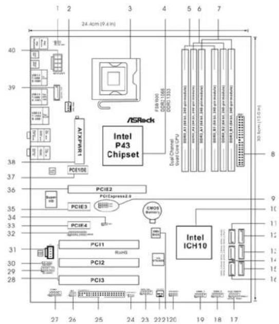
1 PS2_USB_PWR1 Jumper 21 SPI BIOS Chip
2 CPU Fan Connector (CPU_FAN1)
3775-PinCPU Socket 23FrontPanelIEEE1394Header
4 North Bridge Controller
52x240-pin DDR2 DIMM Slots
(Dual Channel A: DDRII_A1, DDRII_B1; Yellow)
6 2x240-pin DDR2 DIMM Slots
Dual Channel B:DDRI_A2,DDRI_B2;Orange)
7 2 x 240-pin DDR3 DIMM Slots
(Dual Channel C: DDR3_A1, DDR3_B1; Green)
8 IDE1 Connector (IDE1, Blue)
9 FSB2 / FSB3 Jumpers
10 South Bridge Controller
11 SATAll Connector (SATAI1 Port0, Red)
12 SATAll Connector (SATAI1_2 (Port1), Red)
13 SATAll Connector (SATAll 4 (Port3), Red)
14 SATAll Connector (SATAll_3 (Port2), Red)
15 SATAll Connector (SATAI16(Port5),Orange)
16 SATAll Connector (SATAll 5 (Port4), Red)
17 System Panel Header (PANEL1)
18 USB 2.0 Header (USB4 5, Blue)
19 USB 2.0 Header (USB6_7, Blue)
20 Chassis Speaker Header (SPEAKER1)
Header
22 Chassis Fan Connector (CHA FAN1)
ONT_1394)
24 Clear CMOS Jumper (CLRCMOS1)
25 Floppy Connector (FLOPPY1)
26 DeskExpress Hot Plug Detection Header
(1R1)
27 COM Port Header (COM1)
28 PCI Slots (PCI1-3)
29 Front Panel Audio Header (HD AUDIO01)
30HDMI_SPDIFHeader(HDMI_SPDIF1)
31 Internal Audio Connector: CD1 (Black)
32 WIFlE Header (WIFlE)
33 PCI Express x1 Slot (PCIE4)
34 FSB1 Jumper
35 PCI Express x1 Slot (PCIE3)
36PCI Express 2.0 x16 Slot (PCIE2,Green)
37 PCI Express x1 Slot (PCIE1/DE)
38 ATX Power Connector (ATXPWR1)
39 eSATAI Connector (eSATAI TOP)
40ATX 12V Connector (ATX12V1)

Motherboard LwataeBtBtBnrs1600ains1600)
1 PS2_USB_PWR1 Jumper 20 Chassis Speaker Header (SPEAKER 1)
2 CPU Fan Connector (CPU_FAN1) 21 SPI BIOS Chip
3 775-Pin CPU Socket
22 Chassis Fan Connector (CHA_FAN1)
4 North Bridge Controller 23 Clear CMOS Jumper (CLRCMOS1)
5 2 x 240-pin DDR2 DIMM Slots 24 Floppy Connector (FLOPPY1)
(Dual Channel A: DDRII_A1, DDRII_B1; Yellow)
25 DeskExpress Hot Plug Detection Header
62x240-pin DDR2 DIMM Slots
26 COM Port Header (COM1)
72x240-pin DDR3 DIMM Slots 27 PCI Slots (PCI1-3)
(Dual Channel C: DDR3_A1, DDR3_B1; Green)
8 IDE1 Connector (IDE1, Blue)
28 Front Panel Audio Header (HD_AUDIO1)
9 FSB2/FSB3 Jumpers
29 HDMI_SPDIF Header (HDMI_SPDIF1)
10 South Bridge Controller
30 Internal Audio Connector: CD1 (Black)
11 SATAll Connector (SATAI1_1 (Port0), Red)
31 WIFl/E Header (WIFlE)
12 SATAll Connector (SATAll 2 (Port1), Red)
32 PCI Express x1 Slot (PCIE4)
13 SATAll Connector (SATAI4 (Port3), Red)
34 PCI Express x1 Slot (PCIE3)
14 SATAll Connector (SATAI3 (Port2), Red)
35PCI Express 2.0 x16 Slot (PCIE2,Green)
15 SATAll Connector (SATAI_6 (Port5), Or
36 PCI Express x1 Slot (PCIE1/DE)
16 SATAll Connector (SATAI5 (Port4), Red)
37 ATX Power Connector (ATXPWR1
17 System Panel Header (PANEL1)
38 eSATAI Connector (eSATAI TOP)
18 USB 2.0 Header (USB4 5, Blue)
39ATX 12V Connector (ATX12V1)
19 USB 2.0 Header (USB6 7, Blue)
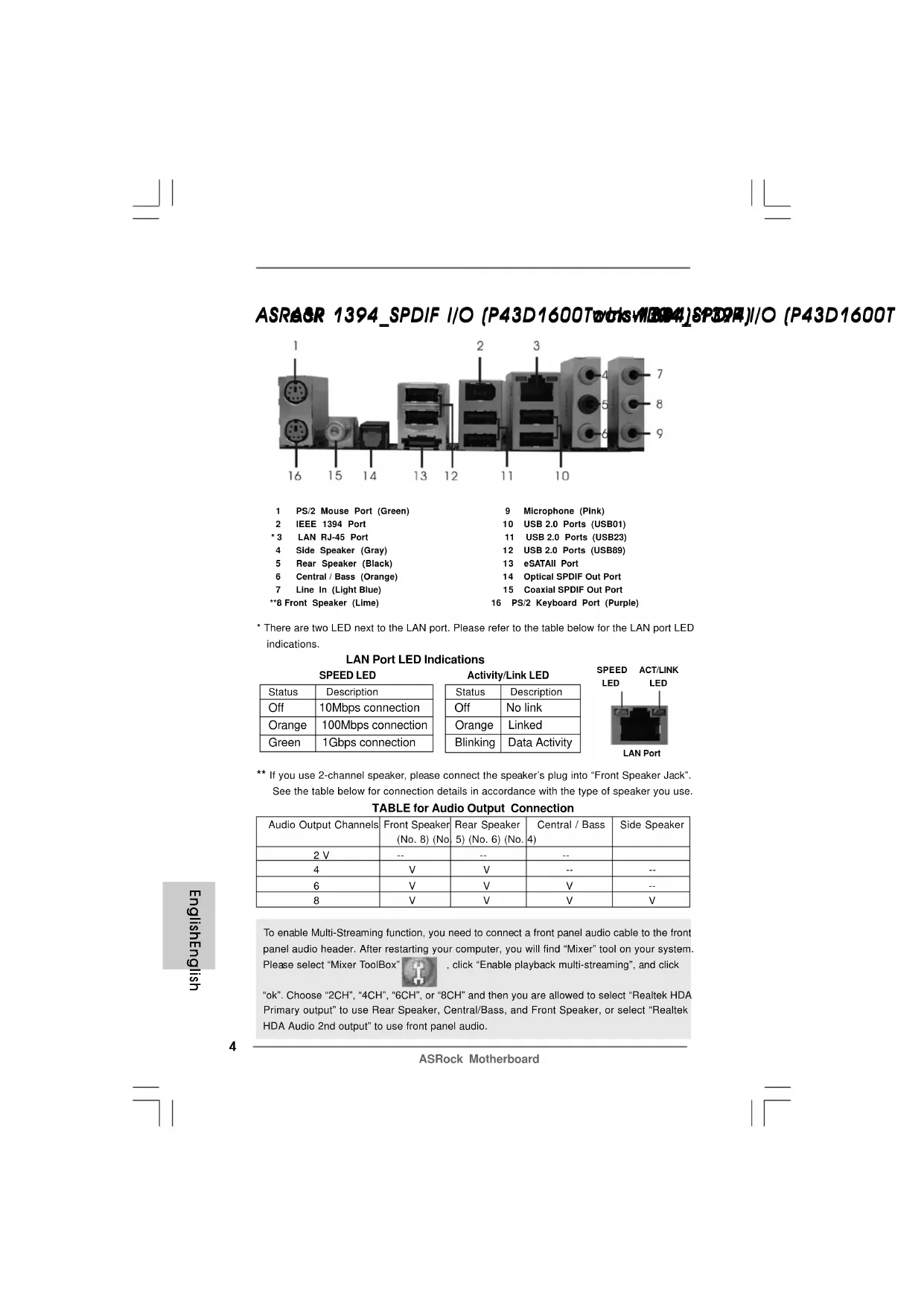
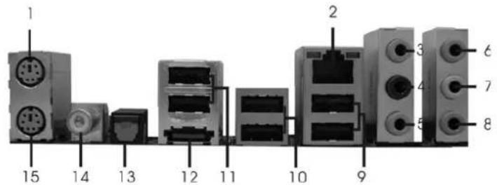
ASRAGR 1394_SPDIF I/O (P43D1600TwrisWB4)SPD4)I/O (P43D1600T
1 PS/2 Mouse Port (Green)
2 IEEE 1394 Port
*3 LAN RJ-45 Port
4 Side Speaker (Gray)
5 Rear Speaker (Black)
6 Central / Bass (Orange)
7 Line In (Light Blue)
**8 Front Speaker (Lime)
9 Microphone (Pink)
10 USB 2.0 Ports (USB01)
11 USB 2.0 Ports (USB23)
12 USB 2.0 Ports (USB89)
13 eSATAI Port
14 Optical SPDIF Out Port
15 Coaxial SPDIF Out Port
16 PS/2 Keyboard Port (Purple)
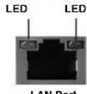
- There are two LED next to the LAN port. Please refer to the table below for the LAN port LED indications.
LAN Port LED Indications
SPEEDLED
| Status | Description |
| Off | 10Mbps connection |
| Orange | 100Mbps connection |
| Green | 1Gbps connection |
Activity/Link LED
| Status | Description |
| Off | No link |
| Orange | Linked |
| Blinking | Data Activity |
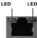
SPEED ACT/LINK
LAN Port
** If you use 2-channel speaker, please connect the speaker's plug into "Front Speaker Jack". See the table below for connection details in accordance with the type of speaker you use.
TABLE for Audio Output Connection
| Audio Output Channels | Front Speaker (No. 8) (No. | Rear Speaker (5) (No. 6) (No. | Central / Bass (4) | Side Speaker |
| 2 V | -- | -- | -- | |
| 4 | V | V | -- | -- |
| 6 | V | V | V | -- |
| 8 | V | V | V | V |
To enable Multi-Streaming function, you need to connect a front panel audio cable to the front panel audio header. After restarting your computer, you will find "Mixer" tool on your system
Please select "Mixer ToolBox"

, click "Enable playback multi-streaming", and click
"ok". Choose "2CH", "4CH", "6CH", or "8CH" and then you are allowed to select "Realtek HDA Primary output" to use Rear Speaker, Central/Bass, and Front Speaker, or select "Realtek HDA Audio 2nd output" to use front panel audio.
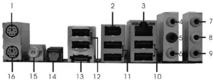
ASRAGR SPDIF I/O (P43D1600Twrks)SPDSF I/O (P43D1600T
1 PS/2 Mouse Port (Green)
2 LAN RJ-45 Port
3 Side Speaker (Gray)
4 Rear Speaker (Black)
5 Central / Bass (Orange)
6 Line In (Light Blue)
7 Front Speaker (Lime)
8 Microphone (Pink)
9 USB 2.0 Ports (USB01)
10 USB2.0 Ports (USB23)
11 USB 2.0 Ports (USB89)
12 eSATAI Port
13 Optical SPDIF Out Port
14 Coaxial SPDIF Out Port
15 PS/2 Keyboard Port (Purple)
- There are two LED next to the LAN port. Please refer to the table below for the LAN port LED indications.
LAN Port LED Indications
SPEEDLED
| Status | Description |
| Off | 10Mbps connection |
| Orange | 100Mbps connection |
| Green | 1Gbps connection |
Activity/Link LED
SPEED ACT/LINK
| Status | Description |
| Off | No link |
| Orange | Linked |
| Blinking | Data Activity |
** If you use 2-channel speaker, please connect the speaker's plug into "Front Speaker Jack". See the table below for connection details in accordance with the type of speaker you use.
TABLE for Audio Output Connection
| Audio Output Channels | Front Speaker (No. 7) (No | Rear Speaker 4) (No. 5) (No. | Central / Bass 3) | Side Speaker |
| 2 V -- | -- | -- | ||
| 4 | V | V | -- | -- |
| 6 | V | V | V | -- |
| 8 | V | V | V | V |
To enable Multi-Streaming function, you need to connect a front panel audio cable to the front panel audio header. After restarting your computer, you will find "Mixer" tool on your system.
Please select "Mixer ToolBox", click "Enable playback multi-streaming", and click
"ok". Choose "2CH", "4CH", "6CH", or "8CH" and then you are allowed to select "Realtek HDA Primary output" to use Rear Speaker, Central/Bass, and Front Speaker, or select "Realtek HDA Audio 2nd output" to use front panel audio.
ASRA&R SPDIF I/O (P43Twrks 800fW/6s19600)

1 PS/2 Mouse Port (Green) 9 USB 2.0 Ports (USB01)
2 LAN RJ-45 Port 10 USB 2.0 Ports (USB23)
3 Side Speaker (Gray) 11 USB 2.0 Ports (USB89)
4 Rear Speaker (Black) 12 eSATAll Port
5 Central / Bass (Orange)
6 Line In (Light Blue)
- 7 Front Speaker (Lime)
8 Microphone (Pink)
13 Optical SPDIF Out Port
14 Coaxial SPDIF Out Port
15 PS/2 Keyboard Port (Purple)
- If you use 2-channel speaker, please connect the speaker's plug into "Front Speaker Jack". See the table below for connection details in accordance with the type of speaker you use.
TABLE for Audio Output Connection
| Audio Output Channels | Front Speaker (No. 7) | Rear Speaker (No. 4) | Central / Bass (No. 5) | Side Speaker (No. 3) |
| 2 | V | -- | -- | -- |
| 4 | V | V | -- | -- |
| 6 | V | V | V | |
| 8 | V | V | V |
To enable Multi-Streaming function, you need to connect a front panel audio cable to the front panel audio header. After restarting your computer, you will find "Mixer" tool on your system. Please select "Mixer ToolBox", click "Enable playback multi-streaming", and click
"ok". Choose "2CH", "4CH", "6CH", or "8CH" and then you are allowed to select "Realtek HDA Primary output" to use Rear Speaker, Central/Bass, and Front Speaker, or select "Realtek HDA Audio 2nd output" to use front panel audio.
1. Introduction1. Introduction
Thank you for purchasing ASRock P43D1600Twins-1394 / P43D1600Twins / P43Twins1600 motherboard, a reliable motherboard produced under ASRock's consistently stringent quality control. It delivers excellent performance with robust design conforming to ASRock's commitment to quality and endurance.
This Quick Installation Guide contains introduction of the motherboard and step-by-step installation guide. More detailed information of the motherboard can be found in the user manual presented in the Support CD.

Because the motherboard specifications and the BIOS software might be updated, the content of this manual will be subject to change without notice. In case any modifications of this manual occur, the updated version will be available on ASRock website without further notice. You may find the latest VGA cards and CPU support lists on ASRock website as well. ASRock website http://www.asrock.com If you require technical support related to this motherboard, please visit our website for specific information about the model you are using. www.asrock.com/support/index.asp
1.1 Package Contentsage Contents
ASRock P43D1600Twins-1394 / P43D1600Twins / P43Twins1600 Motherboard
(ATX Form Factor: 12.0-in x 9.6-in, 30.5 cm x 24.4 cm)
ASRock P43D1600Twins-1394 / P43D1600Twins / P43Twins1600 Quick
Installation Guide
ASRock P43D1600Twins-1394 / P43D1600Twins / P43Twins1600 Support CD
One 80-conductor Ultra ATA 66/100/133 IDE Ribbon Cable
One Ribbon Cable for a 3.5-in Floppy Drive
Four Serial ATA (SATA) Data Cables (Optional) (P43D1600Twins-1394 / P43D1600Twins)
Two Serial ATA (SATA) Data Cables (Optional) (P43Twins1600)
One Serial ATA (SATA) HDD Power Cable (Optional)
One HDMI_SPDIF Cable (Optional)
One "ASRock 1394_SPDIF I/O" I/O Panel Shield (P43D1600Twins-1394)
One "ASRock SPDIF I/O" I/O Panel Shield (P43D1600Twins / P43Twins1600)
1.21. SpecificationsSpecifications
| Platform - ATX Form Factor: 12.0-in x 9.6-in, 30.5 cm x 24.4 cm - All Solid Capacitor design (For P43D1600Twins-1394 / P43D1600Twins Only) | |
| CPU - LGA 775 for | Intel® Core™ 2 Extreme / Core™ 2 Quad / Core™ 2 Duo / Pentium® Dual Core / Celeron®, supporting Penryn Quad Core Yorkfield and Dual Core Wolfdale processors - Supports FSB1600/1333/1066/800 MHz (see CAUTION 1) - Supports Hyper-Threading Technology (see CAUTION 2) - Supports Untied Overclocking Technology (see CAUTION 3) - Supports EM64T CPU |
| Chipset - Northbridge | Intel® P43 - Southbridge: Intel® ICH10 |
| Memory - Dual Channel DDR3/DDR2 Memory Technology (see CAUTION 4) - 2 x DDR3 DIMM slots - Support DDR3 1333/1066 non-ECC, un-buffered memory (see CAUTION 5) - Max. capacity of system memory: 4GB (see CAUTION 6) - 4 x DDR2 DIMM slots - Support DDR2 1066/800/667 non-ECC, un-buffered memory (see CAUTION 5) - Max. capacity of system memory: 16GB (see CAUTION 6) | |
| Expansion Slot - 1 x PCI Express 2.0 x16 slot (green @ x16 mode) - 3 x PCI Express x1 slots - 3 x PCI slots | |
| Audio - 7.1 CH Win | Vista™ Premium Level HD Audio (ALC888 Audio Codec) |
| LAN - PCIE x1 Gigabit LAN 10/100/1000 Mb/s - Realtek RTL8111B/RTL8111C - Supports Wake-On-LAN | |
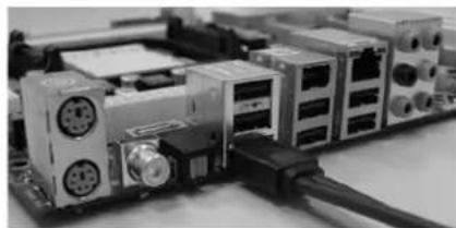
| Rear Panel I/O P43D1600Twins-1394 | |
| ASRock 1394_SPDIF I/O - 1 x PS/2 Mouse Port - 1 x PS/2 Keyboard Port - 1 x Coaxial SPDIF Out Port - 1 x Optical SPDIF Out Port - 6 x Ready-to-Use USB 2.0 Ports - 1 x eSATAI Port - 1 x RJ-45 LAN Port with LED (ACT/LINK LED and SPEED LED) | |
| - 1 x IEEE 1394 Port - HD Audio Jack: Side Speaker/Rear Speaker/Central/Bass/Line in/Front Speaker/Microphone (see CAUTION 7) P43D1600Twins/P43Twins1600 ASRock SPDIF I/O - 1 x PS/2 Mouse Port - 1 x PS/2 Keyboard Port - 1 x Coaxial SPDIF Out Port - 1 x Optical SPDIF Out Port - 6 x Ready-to-Use USB 2.0 Ports - 1 x eSATAI Port - 1 x RJ-45 LAN Port with LED (ACT/LINK LED and SPEED LED) (P43D1600Twins) - 1 x RJ-45 LAN Port (P43Twins1600) - HD Audio Jack: Side Speaker/Rear Speaker/Central/Bass/Line in/Front Speaker/Microphone (see CAUTION 7) | |
| Connector | - 6 x SATAI 3.0Gb/s connectors, support NCQ, AHCI and "Hot Plug" functions (see CAUTION 8) - 1 x eSATAI 3.0Gb/s connector (shared with 1 SATAI port) (see CAUTION 9) - 1 x ATA133 IDE connector (supports 2 x IDE devices) - 1 x Floppy connector - 1 x DeskExpress Hot Plug Detection header - 1 x COM port header - 1 x HDMI_SPDIF header - 1 x IEEE 1394 header (P43D1600Twins-1394) - CPU/Chassis FAN connector - 24 pin ATX power connector - 8 pin 12V power connector (P43D1600Twins-1394 / P43D1600Twins) - 4 pin 12V power connector (P43Twins1600) - CD in header - Front panel audio connector - 2 x USB 2.0 headers (support 4 USB 2.0 ports) (see CAUTION 10) - 1 x WiFi/E header (see CAUTION 11) |
| BIOS Feature | - 8Mb AMI BIOS (P43D1600Twins-1394 / P43D1600Twins) - 4Mb AMI BIOS (P43Twins1600) - AMI Legal BIOS - Supports "Plug and Play" - ACPI 1.1 Compliance Wake Up Events - Supports jumperfree |
| - AMBIOS 2.3.1 Support - CPU, DRAM, NB, SB, VTT Voltage Multi-adjustment - Supports I. O. T. (Intelligent Overclocking Technology) | |
| Support CD - Drivers, Utilities, AntiVirus Software (Trial Version) | |
| Unique Feature | - ASRock OC Tuner (see CAUTION 12) - Hybrid Booster: - CPU Frequency Stepless Control (see CAUTION 13) - ASRock U-COP (see CAUTION 14) - Boot Failure Guard (B.F.G.) |
| Hardware - CPU Temperature Sensing Monitor - Chassis Temperature Sensing - CPU Fan Tachometer - Chassis Fan Tachometer - CPU Quiet Fan - Voltage Monitoring: +12V, +5V, +3.3V, CPU Vcore | |
| OS - Microsoft | ® Windows® 2000 / XP / XP 64-bit / Vista™ / Vista™ 64-bit compliant (see CAUTION 15) |
| Certifications - FOC, CE, WHQL | |
- For detailed product information, please visit our website: http://www.asrock.com
WARNING
Please realize that there is a certain risk involved with overclocking, including adjusting the setting in the BIOS, applying Untied Overclocking Technology, or using the third-party overclocking tools. Overclocking may affect your system stability, or even cause damage to the components and devices of your system. It should be done at your own risk and expense. We are not responsible for possible damage caused by overclocking.
CAUTION!
- This motherboard supports native FSB1600/1333/1066/800 MHz. For normal operation, you do no need to adjust the jumper settings. For special overclocking mode, please refer to page 19 for proper jumper settings.
- About the setting of "Hyper Threading Technology", please check page 45 of "User Manual" in the support CD.
- This motherboard supports Untied Overclocking Technology. Please read "Untied Overclocking Technology" on page 30 for details.
- This motherboard supports Dual Channel Memory Technology. Before you implement Dual Channel Memory Technology, make sure to read the installation guide of memory modules on page 16 for proper installation.
- Please check the table below for the CPU FSB frequency and its corresponding memory support frequency.
| CPU FSB Frequency Memory Support Frequency | |
| 1600 DDR2 800 | DDR2 1066, DDR3 1066, DDR3 1333 |
| 1333 DDR2 667 | DDR2 800, DDR2 1066, DDR3 1066, DDR3 1333 |
| 1066 DDR2 667 | DDR2 800, DDR2 1066, DDR3 1066 |
| 800 DDR2 667, DDR2 800 | |
- Due to the operating system limitation, the actual memory size may be less than 4GB for the reservation for system usage under Windows XP and Windows Vista™. For Windows XP 64-bit and Windows Vista™ 64-bit with 64-bit CPU, there is no such limitation.
- For microphone input, this motherboard supports both stereo and mono modes. For audio output, this motherboard supports 2-channel, 4-channel, 6-channel, and 8-channel modes. Please check the table on page 4, 5 and 6 for proper connection.
- Before installing SATAll hard disk to SATAll connector, please read the "SATAll Hard Disk Setup Guide" on page 34 of "User Manual" in the support CD to adjust your SATAll hard disk drive to SATAll mode. You can also connect SATA hard disk to SATAll connector directly.
- This motherboard supports eSATAIl interface, the external SATAI specification. Please read "eSATAIl Interface Introduction" on page 26 for details about eSATAI and eSATAI installation procedures.
- Power Management for USB 2.0 works fine under Microsoft Windows Vista™ 64-bit / Vista™ / XP 64-bit / XP SP1 or SP2 / 2000 SP4.
-
WiFi/E header supports WiFi+AP function with ASRock WiFi-802.11g or WiFi-802.11n module, an easy-to-use wireless local area network (WLAN) adapter. It allows you to create a wireless environment and enjoy the convenience of wireless network connectivity. Please visit our website for the availability of ASRock WiFi-802.11g or WiFi-802.11n module. ASRock website http://www.asrock.com
-
It is a user-friendly ASRock overclocking tool which allows you to surveil your system by hardware monitor function and overclock your hardware devices to get the best system performance under Windows® environment. Please visit our website for the operation procedures of ASRock OC Tuner. ASRock website: http://www.asrock.com
- Although this motherboard offers stepless control, it is not recommended to perform over-clocking. Frequencies other than the recommended CPU bus frequencies may cause the instability of the system or damage the CPU.
- While CPU overheat is detected, the system will automatically shutdown. Before you resume the system, please check if the CPU fan on the motherboard functions properly and unplug the power cord, then plug it back again. To improve heat dissipation, remember to spray thermal grease between the CPU and the heatsink when you install the PC system.
- AHCI function is not supported under Windows®2000 OS. It is recommended to use IDE mode under Windows® 2000. Please refer to page 51 of "User Manual" in the support CD for detailed setup.
1.31.91imum Hardware Rnunrme HataTeaBefe for
WindowsWhidaWpsPemlum 2008 and Basic Logo Premium 2008 and Basic Logo
For system integrators and users who purchase this motherboard and plan to submit Windows® Vista™ Premium 2008 and Basic logo, please follow below table for minimum hardware requirements.
| CPU Celeron | 420 |
| Memory 1GB | system memory (Premium) |
| 512MB Single Channel (Basic) | |
| VGA | DX10 with WDDM Driver |
| with 128bit VGA memory (Premium) | |
| with 64bit VGA memory (Basic) |
- After June 1, 2008, all Windows® Vista™ systems are required to meet above minimum hardware requirements in order to qualify for Windows® Vista™ Premium 2008 logo.
2. InstallationInstallation
Pre-installation PrecautionsPre-installation Precautions
Take note of the following precautions before you install motherboard components or change any motherboard settings.
- Unplug the power cord from the wall socket before touching any component. Failure to do so may cause severe damage to the motherboard, peripherals, and/or components.
- To avoid damaging the motherboard components due to static electricity, NEVER place your motherboard directly on the carpet or the like. Also remember to use a grounded wrist strap or touch a safety grounded object before you handle components.
- Hold components by the edges and do not touch the ICs.
- Whenever you uninstall any component, place it on a grounded antstatic pad or in the bag that comes with the component.
- When placing screws into the screw holes to secure the motherboard to the chassis, please do not over-tighten the screws! Doing so may damage the motherboard.
2.12CPU InstallationCPU Installation
For the installation of Intel 775-LAND CPU, please follow the steps below.
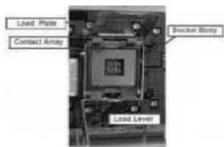
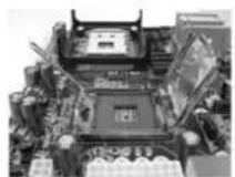
775-Pin Socket Overview

Before you insert the 775-LAND CPU into the socket, please check if the CPU surface is unclean or if there is any bent pin on the socket. Do not force to insert the CPU into the socket if above situation is found. Otherwise, the CPU will be seriously damaged.
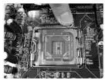
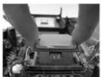
Step 1. Open the socket:
Step 1-1. Disengaging the lever by depressing down and out on the hook to clear retention tab.
Step 1-2. Rotate the load lever to fully open position at approximately 135 degrees.
Step 1-3. Rotate the load plate to fully open position at approximately 100 degrees.
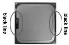
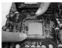
Step 2. Insert the 775-LAND CPU:
Step 2-1. Hold the CPU by the edges where are marked with black lines.
Step 2-2. Orient the CPU with IHS (Integrated Heat Sink) up. Locate Pin1 and the two orientation key notches.
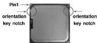
775-LAND CPU
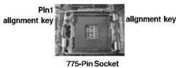

For proper inserting, please ensure to match the two orientation key notches of the CPU with the two alignment keys of the socket.
Step 2-3. Carefully place the CPU into the socket by using a purely vertical motion.
Step 2-4. Verify that the CPU is within the socket and properly mated to the orient keys.
Step 3. Remove PnP Cap (Pick and Place Cap): Use your left hand index finger and thumb to support the load plate edge, engage PnP cap with right hand thumb and peel the cap from the socket while pressing on center of PnP cap to assist in removal.
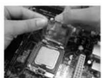

- It is recommended to use the cap tab to handle and avoid kicking off the PnP cap.
- This cap must be placed if returning the motherboard for after service.
Step 4. Close the socket:
Step 4-1. Rotate the load plate onto the IHS.
Step 4-2. While pressing down lightly on load plate, engage the load lever.
Step 4-3. Secure load lever with load plate tab under retention tab of load lever.
2.22.Installation of CPU Fan and HeatsinkInstallation of CPU Fan and Heatsink
For proper installation, please kindly refer to the instruction manuals of your CPU fan and heatsink.
Below is an example to illustrate the installation of the heatsink for 775-LAND CPU.
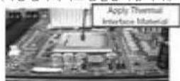
Step 1. Apply thermal interface material onto center of IHS on the socket surface.
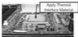
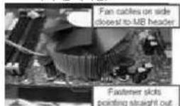
Step 2. Place the heatsink onto the socket. Ensure fan cables are oriented on side closest to the CPU fan connector on the motherboard (CPU_FAN1, see page 2/3, No. 2).
Step 3. Align fasteners with the motherboard throughholes.
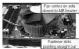
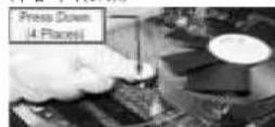
Step 4. Rotate the fastener clockwise, then press down on fastener caps with thumb to install and lock. Repeat with remaining fasteners.
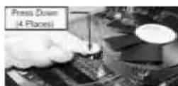

If you press down the fasteners without rotating them clockwise, the heatsink cannot be secured on the motherboard.
Step 5. Connect fan header with the CPU fan connector on the motherboard.
Step 6. Secure excess cable with tie-wrap to ensure cable does not interfere with fan operation or contact other components.
2.3 Installation of Memor2.Mobules1qDMMy Werdates (DIMM)
This motherboard provides four 240-pin DDR2 (Double Data Rate 2) DIMM slots and two 240-pin DDR3 (Double Data Rate 3) DIMM slots, and supports Dual Channel Memory Technology. For dual channel configuration, you always need to install identical (the same brand, speed, size and chip-type) DDR2/DDR3 DIMM pair in the slots of the same color. In other words, you have to install identical DDR2 DIMM pair in Dual Channel A (DDRII_A1 and DDRII_B1; Yellow slots; see p.2/3 No.5), identical DDR2 DIMM pair in Dual Channel B (DDRII_A2 and DDRII_B2; Orange slots; see p.2/3 No.6), or identical DDR3 DIMM pair in Dual Channel C (DDR3_A1 and DDR3_B1; Green slots; see p.2/3 No.7), so that Dual Channel Memory Technology can be activated. This motherboard also allows you to install four DDR2 DIMMs for dual channel configuration, and please install identical DDR2 DIMMs in all four slots. You may refer to the Dual Channel Memory Configuration Table below.
Dual Channel DDR2 Memory Configurations
(DS: Double Side, SS: Single Side)
| DDRII_A1 (Yellow Slot) | DDRII_A2 (Orange Slot) | DDRII_B1 (Yellow Slot) | DDRII_B2 (Orange Slot) | |||||
| 2 memory modules | SS | X | SS | X | ||||
| 2 memory modules | DS | X | DS | X | ||||
| 2 memory modules | X | SS | X | SS | ||||
| 2 memory modules | X | DS | X | DS | ||||
| 4 memory modules | SS | SS | SS | SS | ||||
| 4 memory modules | DS | DS | DS | DS | ||||
Dual Channel DDR3 Memory Configurations
(DS: Double Side, SS: Single Side)
| DDR3_A1 (Green Slot) | DDR3_B1 (Green Slot) | |
| 2 memory modules | SS | SS |
| 2 memory modules | DS | DS |
-
If you want to install two memory modules, for optimal compatibility and reliability, it is recommended to install them in the slots of the same color. In other words, install them in the set of green slots (DDR3_A1 and DDR3_B1), in the set of yellow slots (DDRII_A1 and DDRII_B1), or in the set of orange slots (DDRII_A2 and DDRII_B2).
-
If only one memory module or three memory modules are installed in the DDR2 DIMM slots on this motherboard, it is unable to activate the Dual Channel Memory Technology. If only one memory module is installed in the DDR3 DIMM slots on this motherboard, it is unable to activate the Dual Channel Memory Technology.
- If a pair of memory modules is NOT installed in the same Dual Channel, for example, installing a pair of memory modules in DDR1A1 and DDR1B2, it is unable to activate the Dual Channel Memory Technology.
- It is not allowed to install a DDR3 memory module into DDR2 slot or install a DDR2 memory module into DDR3 slot; otherwise, this motherboard and DIMM may be damaged.
- DDR2 and DDR3 memory modules cannot be installed on this motherboard at the same time.
Installing a DIMMInstalli ng a DIMM

Please make sure to disconnect power supply before adding or removing DIMMs or the system components.
Step 1. Unlock a DIMM slot by pressing the retaining clips outward.
Step 2. Align a DIMM on the slot such that the notch on the DIMM matches the break on the slot.
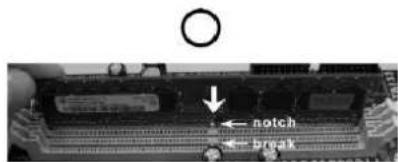
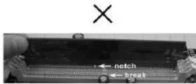

The DIMM only fits in one correct orientation. It will cause permanent damage to the motherboard and the DIMM if you force the DIMM into the slot at incorrect orientation.
Step 3. Firmly insert the DIMM into the slot until the retaining clips at both ends fully snap back in place and the DIMM is properly seated.
2.4 Expansion Slots (PCI and PCI Express Slots)2.4 Expansion Slots (PCI and PCI Expr
There are 3 PCI slots and 4 PCI Express slots on this motherboard.
PCI slots: PCI slots are used to install expansion cards that have the 32-bit PCI interface.
PCIE slots: PCIE1/DE (PCIE x1 slot; White) is used for PCI Express cards with x1 lane width cards, such as Gigabit LAN card, SATA2 card and ASRock PCIE_DE card.
PCIE2 (PCIE x16 slot; Green) is used for PCI Express cards with x16 lane width graphics cards.
PCIE3 / PCIE4 (PCIE x1 slot; White) is used for PCI Express cards with x1 lane width cards, such as Gigabit LAN card, SATA2 card, etc.

If you want to use ASRock DeskExpress function on this motherboard, please install ASRock PCIE_DE card on PCIE1/DE slot.
Installing an expansion cardInstallang an expansion card
Step 1. Before installing the expansion card, please make sure that the power supply is switched off or the power cord is unplugged. Please read the documentation of the expansion card and make necessary hardware settings for the card before you start the installation.
Step 2. Remove the bracket facing the slot that you intend to use. Keep the screws for later use.
Step 3. Align the card connector with the slot and press firmly until the card is completely seated on the slot.
Step 4. Fasten the card to the chassis with screws.
2.5 Jumpers Setup2.5 Jumpers Setup
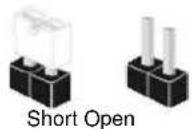
The illustration shows how jumpers are setup. When the jumper cap is placed on pins, the jumper is "Short". If no jumper cap is placed on pins, the jumper is "Open". The illustration shows a 3-pin jumper whose pin1 and pin2 are "Short" when jumper cap is placed on these 2 pins.

Jumper Setting Description
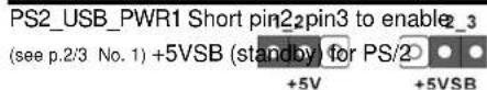
or USB wake up events.
Note: To select +5VSB, it requires 2 Amp and higher standby current provided by power supply.
Clear CMOS Jumper (CLRCMOS1)
(see p.2, No. 24 or p.3, No. 23)


Clear CMOSDefault
Note: CLRCMOS1 allows you to clear the data in CMOS. The data in CMOS includes system setup information such as system password, date, time, and system setup parameters. To clear and reset the system parameters to default setup, please turn off the computer and unplug the power cord from the power supply. After waiting for 15 seconds, use a jumper cap to short pin2 and pin3 on CLRCMOS1 for 5 seconds. However, please do not clear the CMOS right after you update the BIOS. If you need to clear the CMOS when you just finish updating the BIOS, you must boot up the system first, and then shut it down before you do the clear-CMOS action.
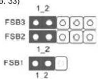
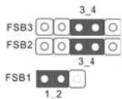
FSB1 Jumper
(FSB1, 3-pin jumper, see p.2 No. 34 or p.3. No. 33)
FSB2 Jumper
(FSB2, 5-pin jumper, see p.2/3 No.9)
Default
FSB3 Jumper
(FSB3, 5-pin jumper, see p.2/3 No.9)
When you mount a FSB800 or FSB1066 CPU, and try to overclock to FSB1333 or FSB1600 (by BIOS setting) you may face the problem, that DRAM frequency will be overclocked very high. Please use jumper to force NB to be strapped at higher frequency, so the DRAM can work at lower frequency.
If you want to overclock the CPU you adopt to FSB1066 on this motherboard, you need to adjust the jumpers. Please short pin4, pin5 for FSB2 jumper and pin4, pin5 for FSB3 jumper. Otherwise, the CPU may not work properly on this motherboard. Please refer to below jumper settings.
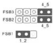
If you want to overclock the CPU you adopt to FSB1333 on this motherboard, you need to adjust the jumpers. Please short pin3, pin4 for FSB2 jumper and pin4, pin5 for FSB3 jumper. Otherwise, the CPU may not work properly on this motherboard. Please refer to below jumper settings.
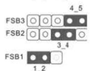
If you want to overclock the CPU you adopt to FSB1600 on this motherboard, you need to adjust the jumpers. Please short pin3, pin4 for FSB2 jumper and pin3, pin4 for FSB3 jumper. Otherwise, the CPU may not work properly on this motherboard. Please refer to below jumper settings. 3.4
2.6 Onboard Headers and Connectors2.6 Onboard Headers and Connectors

Onboard headers and connectors are NOT jumpers. Do NOT place jumper caps over these headers and connectors. Placing jumper caps over the headers and connectors will cause permanent damage of the motherboard!
FDD connector
(33-pin FLOPPY1)
(see p.2 No. 25 or p.3 No. 24)
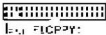
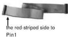
Note: Make sure the red-striped side of the cable is plugged into Pin1 side of the connector.
Primary IDE connector (Blue)
(39-pin IDE1, see p.2/3 No.8)
connect the blue end to the motherboard
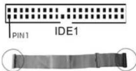
connect the black end to the IDE devices
80-conductor ATA 66/100/133 cable
Note: Please refer to the instruction of your IDE device vendor for the details.
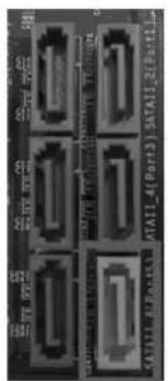
Serial ATAII Connectors These six Serial ATAII (SATAII)
(SATAI_1(Port0): connectors-support SATdata
see p.2/3, No. 11) cables for internal storage
(SATAI_2 (Port1): devices. The current SAT
see p.2/3.No.12)interface affows up to
(SATAI 3 (Port2): data transfer rate
see p.2/3, No. 13)
(SATAll_4(Port3):
see p.2/3, No.14)
(SATAI_5 (Port4):
see p.2/3, No. 16)
(SATAI16(Port5):
see p.2/3.No.15

SATAI_6 (Port5) connector can be used for internal storage device or be connected to eSATAI connector to support eSATAI device. Please read "eSATAI Interface Introduction" on page 26 for details about eSATAI and eSATAI installation procedures.
eSATAI Connector This eSATAI connector
(eSATAI_TOP: supports SATA data cable for
see p.2, No. 39 or p.3 No. 38) external SATAI function. The

esATAIITOP
current eSATAIll interface
allows up to 3.0 Gb/s data
transfer rate.
Serial ATA (SATA) Either end of the SATA data cable
Data Cable can be connected to the SATA /
(Optionai) SATAll hard disk or the SATAll
connector on this motherboard.
You can also use the SATA data
cable to connect SATAll_6 (Port5)
connector and eSATAll connector.
Serial ATA (SATA) Please connect the black end of
Power Cable SATA power cable to the power
(Optional) connection on each drive. Then
HDD power connector

connect to
the power
supply
connect the white end of SATA
power cable to the power
connector of the power supply.
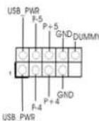
USB 2.0 Headers Besides six default USB 2.0
(9-pin USB6_7) ports on the I/O panel, there are
(see p.2/3 No. 19) two USB 2.0 headers on this
(9-pin USB4 5)
(see p.2/3 No. 18)
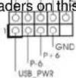
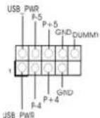
motherboard. Each USB 2.0
header can support two USB
2.0 ports.
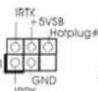
WiFi/E Header This header supports WiFi+AP
(15-pin WIFl/E) function with ASRoK
(see p.2 No. 32 or p.3, No. 31) WiFi-802.11g on WiFi-802.11n
module, an easy-to-use wireless
local area network (WLAN)
adapter. It allows you to create a
wireless environment and enjoy the
convenience of wireless network
connectivity.

If you don't plan to use WiFi+AP functin on this motherboard, this header can be
used as a 4-Pin USB 2.0 header to support one USB 2.0 port. To connect the
4-Pin USB device cable to this header, please refer to
this picture for proper installation.
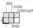
DeskExpress Hot Plug Detection This header supports the Hot
Header Plug detection function for
(5-pin IR1) ASRock DeskExpress.
(see p.2 No. 26 or p.3, No. 25)
Internal Audio Connectors This connector allows you (4-pin CD1) to receive stereo audio input CD-1 GND CD1: see p.2 No.31 or p.3, No.30 from sound sources such as
CD1
a CD-ROM, DVD-ROM, TVtuner card, or MPEG card.
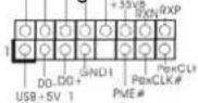
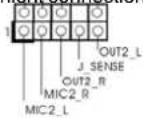
Front Panel Audio Header This is an interface for front (9-pin HD AUDIO01) panel audio cable that allows (see p.2 No. 29 or p.3, No. 28) convenient connection and
control of audio devices.

-
High Definition Audio supports Jack Sensing, but the panel wire on the chassis must support HDA to function correctly. Please follow the instruction in our manual and chassis manual to install your system.
-
If you use AC'97 audio panel, please install it to the front panel audio header as below:
A. Connect Mic_IN (MIC) to MIC2_L
B. Connect Audio_R (RIN) to OUT2_R and Audio_L (LIN) to OUT2_L.
C. Connect Ground (GND) to Ground (GND)
D. MIC_RET and OUT_RET are for HD audio panel only. You don't need to connect them for AC'97 audio panel.
E. Enter BIOS Setup Utility. Enter Advanced Settings, and then select Chipset Configuration. Set the Front Panel Control option from [Auto] to [Enabled].
F. Enter Windows system. Click the icon on the lower right hand taskbar to enter Realtek HD Audio Manager.
For Windows® 2000 / XP / XP 64-bit OS:
Click "Audio I/O", select "Connector Settings", choose
"Disable front panel jack detection", and save the change by clicking "OK".
For Windows Vista™ / Vista™ 64-bit OS:
Click the right-top "Folder" icon , choose "Disable front
panel jack detection", and save the change by clicking "OK".
G. To activate the front mic.
For Windows® 2000 / XP / XP 64-bit OS:
Please select "Front Mic" as default record device.
If you want to hear your voice through front mic, please deselect "Mute" icon in "Front Mic" of "Playback" portion.
For Windows Vista/Vista 64-bit OS:
Go to the "Front Mic" Tab in the Realtek Control panel.
Click "Set Default Device" to make the Front Mic as the default record device.
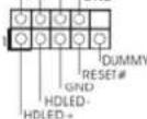
System Panel Header This header accommodates
(9-pin PANEL1) several system front panel
(see p.2/3 No. 17) functions.
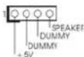
Chassis Speaker Header Please connect the chassis
(4-pin SPEAKER 1) speaker to this header.
(see p.2/3 No. 20)
Chassis Fan Connector Please connect a chassis fan
(3-pin CHA_FAN1) cable to this connector and SPEEC
(see p.2/3 No. 22) match the black wire to the

ground pin.
CPU Fan Connector Please connect a CPU fan cable
(4-pin CPU_FAN1) to this connector and match
(see p.2/3 No. 2) the black wire to the ground pin.

Though this motherboard provides 4-Pin CPU fan (Quiet Fan) support, the 3-Pin
CPU fan still can work successfully even without the fan speed control function.
If you plan to connect the 3-Pin CPU fan to the CPU fan connector on this
motherboard, please connect it to Pin 1-3.
Pin 1-3 Connected
3-Pin Fan Installation
ATX Power Connector Please connect an ATX power
(24-pinATXPWR1)
(see p.2, No. 38 or p.3, No. 37)
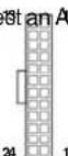
supply to this connector.

Though this motherboard provides 24-pin ATX power connector,
it can still work if you adopt a traditional 20-pin ATX power supply.
To use the 20-pin ATX power supply, please plug your
power supply along with Pin 1 and Pin 13.
20-Pin ATX Power Supply Installation
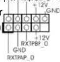
ATX 12V Power Connector Please connect an ATX 12V
(8-pin ATX12V1) power supply to this connector.
(see p.2 No.40)


Though this motherboard provides 8-pin ATX 12V power connector, it can still work if you adopt a traditional 4-pin ATX 12V power supply. To use the 4-pin ATX power supply, please plug your power supply along with Pin 1 and Pin 5.
4-Pin ATX 12V Power Supply Installation
ATX 12V Power Connector
(4-pinATX12V1)
(see p.3 No. 39)

Please connect an ATX 12V
power supply to this connector.
IEEE 1394 Header Besides one default IEEE 1394
(9-pin FRONT_1394) port on the I/O panel, there is one
(see p.2 No. 23) IEEE 1394 header
Serial port Header
(9-pin COM1)
(see p.2 No.27 or p.3 No.26)
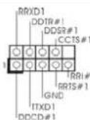
(FRONT_1394) on this motherboard. This IEEE 1394 header can support one IEEE 1394 port.
This COM1 header supports a serial port module.
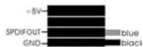
HDMI_SPDIFHeaderHDMI_SPDIFheader,providing
(3-pin HDMI_SPDIF1) SPDIF audio output to HDMI VGA
(see p.2 No.30 or p.3 No.29) card, allows the system to
+5V
connect HDMI Digital TV/ projector/LCD devices. Please connect the HDMI_SPDIF connector of HDMI VGA card to this header.
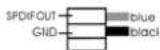
HDMI_SPDIF Cable Please connect the black end (A)
(Optiona) of HDMI_SPDIF cable to the
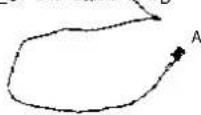
HDMI_SPDIF header on the motherboard. Then connect the white end (B or C) of HDMI_SPDIF cable to the HDMI_SPDIF connector of HDMI VGA card.
A. black end
B. white end (2-pin)

C. white end (3-pin)
2.7 HDMI_SPDIF Header Connection Guide2.7 HDMI_SPDIF Header Connection Guid
HDMI (High-Definition Multi-media Interface) is an all-digital audio/video specification, which provides an interface between any compatible digital audio/video source, such as a set-top box, DVD player, A/V receiver and a compatible digital audio or video monitor, such as a digital television (DTV). This motherboard is equipped with a HDMI_SPDIF header, which provides SPDIF audio output to HDMI VGA card, allows the system to connect HDMI Digital TV/projector/LCD devices. To use HDMI function on this motherboard, please refer to page 30 of "User Manual" in the support CD for detailed installation procedures.
2.8 eSADAB EArAdicTeIntroductiOnface IntroductiOn
NOTE:
- If you set "Configure SATAII as" option in BIOS setup to AHCI mode, Hot Plug function is supported with eSATAI devices. Therefore, you can insert or remove your eSATAI devices to the eSATAI ports while the system is power-on and in working condition.
- If you set "Configure SATAII as" option in BIOS setup to IDE mode, Hot Plug function is not supported with eSATAI devices. If you still want to use eSATAI function in IDE mode, please insert or remove your eSATAI devices to the eSATAI ports only when the system is power-off.
- Please refer to page 28 to 30 for detailed information of IDE mode and AHCI mode.
How to install eSATAI?
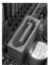
esATAI connector (esATAI)
SATAll connector
SATAll_6 (Port5)
- In order to enable the eSATAI port of the I/O shield, you need to connect the orange SATAll connector (SATAII_6 (Port5); see p.2/3 No.15) and the eSATAll connector (eSATAI_TOP; see p.2 No.39 or p.3 No.38) with a SATA data cable first.
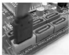
Connect the SATA data cable to the orange SATAll connector (SATAll_6(Port5))
Connect the SATA data cable to the eSATAI connector (eSATAI_TOP)
- Use the eSATAI device cable to connect eSATAI device and the eSATAI port of the I/O shield.
Connect one end of the eSATAI1 device cable to eSATAI device
Connect the other end of the eSATAI device cable to eSATAI port of the I/O shield
2.9 Serial ATA (SATA) / Serial ATAII (SATAII) Hard Disks Installation
This motherboard adopts Intel® ICH10 south bridge chipset that supports Serial ATA (SATA) / Serial ATAII (SATAII) hard disks. You may install SATA / SATAII hard disks on this motherboard for internal storage devices. This section will guide you to install the SATA / SATAII hard disks.
STEP 1: Install the SATA / SATAAll hard disks into the drive bays of your chassis.
STEP 2: Connect the SATA power cable to the SATA / SATAll hard disk.
STEP 3: Connect one end of the SATA data cable to the motherboard's SATA connector.
STEP 4: Connect the other end of the SATA data cable to the SATA / SATAll hard disk.

It is not recommended to switch the "Configure SATAII as" setting after OS installation.
2.102 Driver Installation Guide Driver Installation Guide
To install the drivers to your system, please insert the support CD to your optical drive first. Then, the drivers compatible to your system can be auto-detected and listed on the support CD driver page. Please follow the order from up to bottom side to install those required drivers. Therefore, the drivers you install can work properly.
2.112nfalling Windowsng XWndows4-bit / Vista™ 2000 / XP / XP 64-bit / Vista Vista™ 64-bit Without RAID Functions
If you want to install Windows® 2000 / XP / XP 64-bit / Vista™ / Vista™ 64-bit OS on your SATA / SATAAll HDDs without RAID functions, please follow below procedures according to the OS you install.

Since Windows® 2000 AHCI driver is not provided by the chipset vendor, AHCI function is not supported under Windows® 2000.
2.11.1 Installing Windows2.2000 / X86starXP4Win32000 / XP / XP 64-bit Without RAID FuhotioRAIDcflions
If you want to install Windows® 2000 / XP / XP 64-bit OS on your SATA / SATAII HDDs without RAID functions, please follow below steps.
Using SATA / SATAAll HDDs and eSATAI devices with NCQ function
STEP1: Set Up BIOS.
A. Enter BIOS SETUP UTILITY→Advanced screen →IDE Configuration.
B. Set "SATAI Configuration" to [Enhanced], and then in the option "Configure SATAI as", please set the option to [AHCI].
STEP 2: Make a SATA / SATAll driver diskette.
A. Insert the Support CD into your optical drive to boot your system.
B. During POST at the beginning of system boot-up, press
C. When you see the message on the screen, "Do you want to generate Serial ATA driver diskette [YN]?", press
D. Then you will see these messages,
Please insert a diskette into the floppy drive.
WARNING! Formatting the floppy diskette will
lose ALL data in it!
Start to format and copy files [YN]?
Please insert a floppy diskette into the floppy drive, and press
E. The system will start to format the floppy diskette and copy SATA / SATAI drivers into the floppy diskette.
STEP 3: Install Windows XP / XP 64-bit OS on your system. (Windows 2000 is not supported.)
After making a SATA / SATAAll driver diskette, you can start to install Windows XP / XP 64-bit on your system. At the beginning of Windows setup, press F6 to install a third-party AHCI driver. When prompted, insert the SATA / SATAAll driver diskette containing the Intel® AHCI driver. After reading the floppy disk, the driver will be presented. Select the driver to install according to the mode you choose and the OS you install. You may select: "Intel(R) ICH10 SATA AHCI Controller (Desktop - Windows XP)" for Windows XP or "Intel(R) ICH10 SATA AHCI Controller (Desktop - Windows XP64)" for Windows XP 64-bit.
Using SATA / SATAll HDDs and eSATAI devices without NCQ function
STEP 1: Set up BIOS.
A. Enter BIOS SETUP UTILITY Advanced screen IDE Configuration.
B. Set "SATAII Configuration" to [Enhanced], and then in the option "Configure SATAII as", please set the option to [IDE].
STEP 2: Install Windows® 2000 / XP / XP 64-bit OS on your system.
2.11.2 Installing Windows2.VistotVfshsodMyswod6swit Without RAID Functions
If you want to install Windows Vista™ / Vista™ 64-bit OS on your SATA / SATAAll HDDs without RAID functions, please follow below steps.
Using SATA / SATAAll HDDs and eSATAI devices with NCQ function
STEP 1: Set Up BIOS.
A. Enter BIOS SETUP UTILITY Advanced screen IDE Configuration.
B. Set "SATAI Configuration" to [Enhanced], and then in the option "Configure SATAI as", please set the option to [AHCI].
STEP 2: Install Windows Vista™/Vista™ 64-bit OS on your system.
Insert the Windows® Vista™ / Vista™ 64-bit optical disk into the optical drive to boot your system, and follow the instruction to install Windows® Vista™ / Vista™ 64-bit OS on your system. When you see "Where do you want to install Windows?" page, please insert the ASRock Support CD into your optical drive, and click the "Load Driver" button on the left on the bottom to load the Intel® AHCI drivers. Intel® AHCI drivers are in the following path in our Support CD:
...I386 (For Windows Vista OS)
AMD64 (For Windows® Vista™ 64-bit OS)
After that, please insert Windows Vista™/Vista™ 64-bit optical disk into the optical drive again to continue the installation.
Using SATA / SATAAll HDDs and eSATAI devices without NCQ function
STEP 1: Set up BIOS.
A. Enter BIOS SETUP UTILITY Advanced screen IDE Configuration.
B. Set "SATAI1 Configuration" to [Enhanced], and then in the option "Configure SATAI1 as", please set the option to [IDE].
STEP 2: Install Windows Vista™/Vista™ 64-bit OS on your system.
2.122Unf2ed Overclocking TefahedlgyeochonglyT
This motherboard supports Untied Overclocking Technology, which means during overclocking, FSB enjoys better margin due to fixed PCI / PCIE buses. Before you enable Untied Overclocking function, please enter "Overclock Mode" option of BIOS setup to set the selection from [Auto] to [Manual]. Therefore, CPU FSB is untied during overclocking, but PCI / PCIE buses are in the fixed mode so that FSB can operate under a more stable overclocking environment.

Please refer to the warning on page 10 for the possible overclocking risk before you apply Untied Overclocking Technology.
3. BIOS Information3. BIOS Information
The Flash Memory on the motherboard stores BIOS Setup Utility. When you start up the computer, please press <F2> during the Power-On-Self-Test (POST) to enter BIOS Setup utility; otherwise, POST continues with its test routines. If you wish to enter BIOS Setup after POST, please restart the system by pressing <Ctrl> + <Alt> + <Delete> , or pressing the reset button on the system chassis. The BIOS Setup program is designed to be user-friendly. It is a menu-driven program, which allows you to scroll through its various sub-menus and to select among the predetermined choices. For the detailed information about BIOS Setup, please refer to the User Manual (PDF file) contained in the Support CD.
4. Software Support4.CSsoftwareStipptoCD information
This motherboard supports various Microsoft® Windows® operating systems: 2000 / XP / XP 64-bit / Vista™ / Vista™ 64-bit. The Support CD that came with the motherboard contains necessary drivers and useful utilities that will enhance motherboard features. To begin using the Support CD, insert the CD into your CD-ROM drive. It will display the Main Menu automatically if "AUTORUN" is enabled in your computer. If the Main Menu does not appear automatically, locate and double-click on the file "ASSETUP.EXE" from the BIN folder in the Support CD to display the menus.
Website: www.asrock.com/support/index.asp
1.1 Kartoninhalt
ASRock P43D1600Twins-1394 / P43D1600Twins / P43Twins1600 Motherboard (ATX-Formfactor: 30.5 cm x 24.4 cm; 12.0 Zoll x 9.6 Zoll)
ASRock P43D1600Twins-1394/P43D1600Twins/P43Twins1600
2.1 CPU Installation2.1 CPU Installation
(CLRCMOS1, 3-Pin jumper)
(SATAI_4 (Port3): 3,0 Gb/s.
bedienenden Wireless Local
Area Network (WLAN) Adapter.
formatted diskette into floppy
drive A:
press any key to start
(Orifices des attaches ressortant)

(DS: Double Side (double face), SS: Single Side (simple face))
| DDR3_A1(Slot Vert) | DDR3_B1(Slot Vert) | |
| 2 modules de mémoire | SS | SS |
| 2 modules de mémoire | DS | DS |

US4_5br.9)2portsUSB2.0.
(voir p.2/3 No.18)
formatted diskette into floppy
drive A:
press any key to start
www.asrock.com/support/index.asp
(ATX Form Factor: 12.0-in x 9.6-in, 30.5 cm x 24.4 cm)
Guida di installmente rapida ASRock P43D1600Twins-1394/P43D1600Twins/
P43Twins1600
CD di supporto ASRock P43D1600Twins-1394/P43D1600Twins/P43Twins1600
Un cavo IDE 80-pin Ultra ATA 66/100/133
Un cavo per floppy drive a 1,44 Mb
Dual Channel DDR2 Memory Configurations
(DS: Double Side, SS: Single Side)
Dual Channel DDR3 Memory Configurations
(DS: Double Side, SS: Single Side)
(CLRCMOS1, jumper a 3 pin)
(SATAI 5 (Port4): 3.0 Gb/s. ATA Port
vedi p.2/3 Nr.16)
(SATAll_6(Port5):
vedip.2/3 Nr.15

Please insert a blank formatted diskette into floppy
drive A:
press any key to start
(CLRCMOS1, jumper de 3 pins)
(vea p.2, N. 24 o p.3, N. 23)

predeterminado
formatted diskette into floppy
drive A:
press any key to start
- 4.1.2.3.4.5.6.7.8.9.10.11.12.13.14.15.16.17.18.19.20.21.22.23.24.25.26.27.28.29.30.31.32.33.34.35.36.37.38.39.40.41.42.43.44.45.46.47.48.49.50.51.52.53.54.55.56.57.58.59.60.61.62.63.64.65.66.67.68.69.70.71.72.73.74.75.76.77.78.79.80.81.82.83.84.85.86.87.88.89.90.91.92.93.94.95.96.97.98.99.100
(
(a)
()
(午号

国长电自
iEeBnBcDreAeWiFi+APGcnncnueAaHsHzJnngHgW,iEeHdIe1KoUSB2.0F3eTaeJrwnHcH4PUSB2.0HeTeRouAaHsHcHsuHcHsuHcHsuHcHsuHcHsuHcHsuHcHsuHcHsuHcHsuHcHsuHcHsuHcHsuHcHsuHcHsuHcHsuHcHsuHcHsuHcHsuHcHsuHcHsuHcHsuHcHsuHcHsuHcHsuHcHsuHcHtu
DeskExpress 次普拉二转机捷贝
(5)IR1
(2)[1]36[1]37
S100000000000000000000000000000000000000000000000000000000
新社S形列是I他
..I386 (Windows®VistaTM SA-8J-8)
AMD64 (Windows® Vista™ 64 bit 微小尺寸)
上
NCQgIeSATA/SATAIIHDDeSATAII
## 1:BIOS 就是
A. BIOS SETUP UTILITY (BIOS 设置的用例) Advanced screen (加载画面) IDE Configuration (IDE 部署) 将屏幕加载。
Stépp2:SATA / SATAI I I I I I I I I I I I I I I I I I I I I I I I I I I I I I I I I I I I I I I I
www.asrock.com/support/index.asp
1.1包装盒内物品
华擎P43D1600Twins-1394/P43D1600Twins/P43Twins1600主板