870 Extreme3 R2.0 - Motherboard ASROCK - Free user manual and instructions
Find the device manual for free 870 Extreme3 R2.0 ASROCK in PDF.
Download the instructions for your Motherboard in PDF format for free! Find your manual 870 Extreme3 R2.0 - ASROCK and take your electronic device back in hand. On this page are published all the documents necessary for the use of your device. 870 Extreme3 R2.0 by ASROCK.
USER MANUAL 870 Extreme3 R2.0 ASROCK
ASRock 870 Extreme3 Motherboard EnglishEnglish EnglishEnglish English Copyright Notice:Copyright Notice: Copyright Notice:Copyright Notice: Copyright Notice: No part of this installation guide may be reproduced, transcribed, transmitted, or trans- lated in any language, in any form or by any means, except duplication of documen- tation by the purchaser for backup purpose, without written consent of ASRock Inc. Products and corporate names appearing in this guide may or may not be registered trademarks or copyrights of their respective companies, and are used only for identifica- tion or explanation and to the owners’ benefit, without intent to infringe. Disclaimer:Disclaimer: Disclaimer:Disclaimer: Disclaimer: Specifications and information contained in this guide are furnished for informational use only and subject to change without notice, and should not be constructed as a commitment by ASRock. ASRock assumes no responsibility for any errors or omissions that may appear in this guide. With respect to the contents of this guide, ASRock does not provide warranty of any kind, either expressed or implied, including but not limited to the implied warranties or conditions of merchantability or fitness for a particular purpose. In no event shall ASRock, its directors, officers, employees, or agents be liable for any indirect, special, incidental, or consequential damages (including damages for loss of profits, loss of business, loss of data, interruption of business and the like), even if ASRock has been advised of the possibility of such damages arising from any defect or error in the guide or product. This device complies with Part 15 of the FCC Rules. Operation is subject to the following two conditions: (1) this device may not cause harmful interference, and (2) this device must accept any interference received, including interference that may cause undesired operation. Published March 2011 Copyright©2011 ASRock INC. All rights reserved.
CALIFORNIA, USA ONLY
The Lithium battery adopted on this motherboard contains Perchlorate, a toxic substance controlled in Perchlorate Best Management Practices (BMP) regulations passed by the California Legislature. When you discard the Lithium battery in California, USA, please follow the related regulations in advance. “Perchlorate Material-special handling may apply, see www.dtsc.ca.gov/hazardouswaste/perchlorate” ASRock Website: http://www.asrock.com22
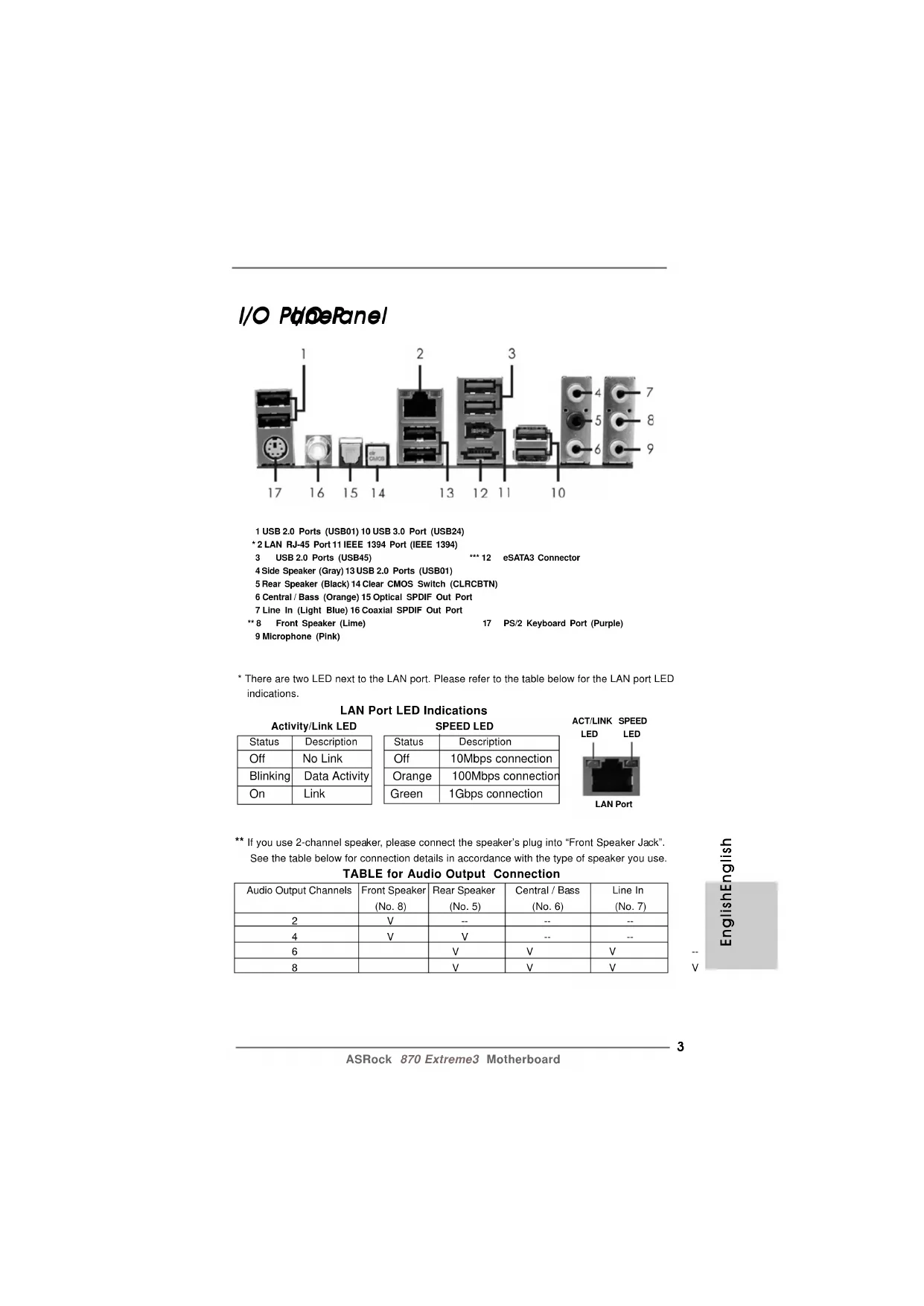
- There are two LED next to the LAN port. Please refer to the table below for the LAN port LED indications. LAN Port LED Indications Activity/Link LED SPEED LED Status Description Status Description Off No Link Off 10Mbps connection Blinking Data Activity Orange 100Mbps connection On Link Green 1Gbps connection ** If you use 2-channel speaker, please connect the speaker’s plug into “Front Speaker Jack”. See the table below for connection details in accordance with the type of speaker you use. TABLE for Audio Output Connection Audio Output Channels Front Speaker Rear Speaker Central / Bass Line In (No. 8) (No. 5) (No. 6) (No. 7) 2 V -- -- -- 4VV---- 6 VVV-- 8 VVVV44
ASRock 870 Extreme3 Motherboard To enable Multi-Streaming function, you need to connect a front panel audio cable to the front panel audio header. After restarting your computer, you will find “Mixer” tool on your system. Please select “Mixer ToolBox” , click “Enable playback multi-streaming”, and click “ok”. Choose “2CH”, “4CH”, “6CH”, or “8CH” and then you are allowed to select “Realtek HDA Primary output” to use Rear Speaker, Central/Bass, and Front Speaker, or select “Realtek HDA Audio 2nd output” to use front panel audio. *** eSATA3 connector supports SATA Gen3 in cable 1M. EnglishEnglish EnglishEnglish English55
IntroductionIntroduction IntroductionIntroduction Introduction Thank you for purchasing ASRock 870 Extreme3 motherboard, a reliable motherboard produced under ASRock’s consistently stringent quality control. It delivers excellent performance with robust design conforming to ASRock’s commitment to quality and endurance. In this manual, chapter 1 and 2 contain introduction of the motherboard and step-by-step guide to the hardware installation. Chapter 3 and 4 contain the configuration guide to BIOS setup and information of the Support CD. Because the motherboard specifications and the BIOS software mightbe updated, the content of this manual will be subject to change withoutnotice. In case any modifications of this manual occur, the updatedversion will be available on ASRock website without further notice. Youmay find the latest VGA cards and CPU support lists on ASRock website as well. ASRock website http://www.asrock.com If you require technical support related to this motherboard, please visitour website for specific information about the model you are using.www.asrock.com/support/index.asp
SpecificationsSpecifications SpecificationsSpecifications Specifications Platform - ATX Form Factor: 12.0-in x 9.6-in, 30.5 cm x 24.4 cm - All Solid Capacitor design CPU - Support for Socket AM3+ processors - Support for Socket AM3 processors: AMD Phenom
II X6 / X4 / X3 / X2 (except 920 / 940) / Athlon II X4 / X3 / X2 / Sempron processors - Supports 8-Core CPU - Supports UCC feature (Unlock CPU Core) (see CAUTION 1) - V4 + 1 Power Phase Design - Supports CPU up to 140W - Supports AMD’s Cool ‘n’ Quiet
Technology - FSB 2600 MHz (5.2 GT/s) - Supports Untied Overclocking Technology (see CAUTION 2) - Supports Hyper-Transport 3.0 (HT 3.0) Technology Chipset - Northbridge: AMD 870 - Southbridge: AMD SB850 Memory - Dual Channel DDR3 Memory Technology (see CAUTION 3) - 4 x DDR3 DIMM slots - Support DDR3 1866(OC)/1800(OC)/1600(OC)/1333/1066/800 non-ECC, un-buffered memory (see CAUTION 4) - Max. capacity of system memory: 32GB (see CAUTION 5) Expansion Slot - 2 x PCI Express 2.0 x16 slot (Single at x16 or dual at x8/x8 mode) - 2 x PCI Express 2.0 x1 slots - 2 x PCI slots - Supports ATI
ASRock 870 Extreme3 Motherboard EnglishEnglish EnglishEnglish English - 1 x RJ-45 LAN Port with LED (ACT/LINK LED and SPEED LED) - 1 x IEEE 1394 Port - 1 x Clear CMOS Switch with LED - HD Audio Jack: Side Speaker/Rear Speaker/Central/Bass/ Line in/Front Speaker/Microphone (see CAUTION 6) SATA3 - 5 x SATA3 6.0 Gb/s connectors, support RAID (RAID 0, RAID 1, RAID 0+1 and RAID 5), NCQ, AHCI and "Hot Plug" functions USB 3.0 - 2 x USB 3.0 port by Etron EJ168A, support USB 1.0/2.0/
Connector - 5 x SATA3 6.0Gb/s connectors - 1 x IR header - 1 x COM port header - 1 x IEEE 1394 header - 1 x HDMI_SPDIF header - 1 x Power LED header - CPU/Chassis/Power FAN connector - 24 pin ATX power connector - 8 pin 12V power connector - Front panel audio connector - 3 x USB 2.0 headers (support 6 USB 2.0 ports) - 1 x Dr. Debug (7-Segment Debug LED) Smart Switch - 1 x Clear CMOS Switch with LED - 1 x Power Switch with LED - 1 x Reset Switch with LED BIOS Feature - 32Mb AMI UEFI Legal BIOS with GUI support - Supports “Plug and Play” - ACPI 1.1 Compliance Wake Up Events - Supports jumperfree - SMBIOS 2.3.1 Support - CPU VID, VCCM, NB, SB Voltage Multi-adjustment Support CD - Drivers, Utilities, AntiVirus Software (Trial Version), AMD OverDrive
ASRock 870 Extreme3 Motherboard EnglishEnglish EnglishEnglish English WARNING Please realize that there is a certain risk involved with overclocking, including adjusting the setting in the BIOS, applying Untied Overclocking Technology, or using the third- party overclocking tools. Overclocking may affect your system stability, or even cause damage to the components and devices of your system. It should be done at your own risk and expense. We are not responsible for possible damage caused by overclocking. - Hybrid Booster: - CPU Frequency Stepless Control (see CAUTION 13) - ASRock U-COP (see CAUTION 14) - Boot Failure Guard (B.F.G.) Hardware - CPU Temperature Sensing Monitor - Chassis Temperature Sensing - CPU/Chassis/Power Fan Tachometer - CPU Quiet Fan - CPU/Chassis Fan Multi-Speed Control - Voltage Monitoring: +12V, +5V, +3.3V, Vcore OS - Microsoft
64-bit / XP / XP Media Center / XP 64-bit compliant Certifications - FCC, CE, WHQL - ErP/EuP Ready (ErP/EuP ready power supply is required) (see CAUTION 15)
- For detailed product information, please visit our website: http://www.asrock.com99
1. ASRock UCC (Unlock CPU Core) feature simplifies AMD CPU activation. As
long as a simple switch of the UEFI option “ASRock UCC”, you can unlock the extra CPU core to enjoy an instant performance boost. When UCC feature is enabled, the dual-core or triple-core CPU will boost to the quad-core CPU, and some CPU, including quad-core CPU, can also increase L3 cache size up to 6MB, which means you can enjoy the upgrade CPU performance with a better price. Please be noted that UCC feature is supported with AM3/AM3+ CPU only, and in addition, not every AM3/AM3+ CPU can support this function because some CPU’s hidden core may be malfunctioned.
2. This motherboard supports Untied Overclocking Technology. Please read “Un-
tied Overclocking Technology” on page 33 for details.
3. This motherboard supports Dual Channel Memory Technology. Before you
implement Dual Channel Memory Technology, make sure to read the installation guide of memory modules on page 14 for proper installation.
4. Whether 1866/1800/1600MHz memory speed is supported depends on the
AM3/AM3+ CPU you adopt. If you want to adopt DDR3 1866/1800/1600 memory module on this motherboard, please refer to the memory support list on our website for the compatible memory modules. ASRock website http://www.asrock.com
5. Due to the operating system limitation, the actual memory size may be
less than 4GB for the reservation for system usage under Windows
OS with 64-bit CPU, there is no such limitation.
6. For microphone input, this motherboard supports both stereo and mono modes.
For audio output, this motherboard supports 2-channel, 4-channel, 6-channel, and 8-channel modes. Please check the table on page 3 for proper connection.
7. ASRock Extreme Tuning Utility (AXTU) is an all-in-one tool to ne-tune
different system functions in a user-friendly interface, which is including Hardware Monitor, Fan Control, Overclocking, OC DNA and IES. In Hard- ware Monitor, it shows the major readings of your system. In Fan Control, it shows the fan speed and temperature for you to adjust. In Overclocking, you are allowed to overclock CPU frequency for optimal system performance. In OC DNA, you can save your OC settings as a profile and share with your friends. Your friends then can load the OC profile to their own system to get the same OC settings. In IES (Intelligent Energy Saver), the voltage regulator can reduce the number of output phases to improve efficiency when the CPU cores are idle without sacrificing computing performance. Please visit our website for the operation proce- dures of ASRock Extreme Tuning Utility (AXTU). ASRock website: http://www.asrock.com1010
8. ASRock Instant Flash is a BIOS flash utility embedded in Flash ROM.
This convenient BIOS update tool allows you to update system BIOS without entering operating systems first like MS-DOS or Windows
. With this utility, you can press <F6> key during the POST or press <F2> key to BIOS setup menu to access ASRock Instant Flash. Just launch this tool and save the new BIOS file to your USB flash drive, floppy disk or hard drive, then you can update your BIOS only in a few clicks without prepar- ing an additional floppy diskette or other complicated flash utility. Please be noted that the USB flash drive or hard drive must use FAT32/16/12 file system.
9. To experience intuitive motion controlled games is no longer only available
at Wii. ASRock AIWI utility introduces a new way of PC gaming operation. ASRock AIWI is the world's first utility to turn your iPhone/iPod touch as a game joystick to control your PC games. All you have to do is just to install the ASRock AIWI utility either from ASRock official website or ASRock software support CD to your motherboard, and also download the free AIWI Lite from App store to your iPhone/iPod touch. Connecting your PC and apple devices via Bluetooth or WiFi networks, then you can start experiencing the exciting motion controlled games. Also, please do not forget to pay attention to ASRock official website regularly, we will continuously provide you the most up-do-date supported games! ASRock website: http://www.asrock.com/Feature/Aiwi/index.asp
10. If you desire a faster, less restricted way of charging your Apple devices,
such as iPhone/iPod/iPad Touch, ASRock has prepared a wonderful solution for you - ASRock APP Charger. Simply installing the APP Charger driver, it makes your iPhone charged much quickly from your computer and up to 40% faster than before. ASRock APP Charger allows you to quickly charge many Apple devices simultaneously and even supports continuous charging when your PC enters into Standby mode (S1), Sus- pend to RAM (S3), hibernation mode (S4) or power off (S5). With APP Charger driver installed, you can easily enjoy the marvelous charging experience than ever. ASRock website: http://www.asrock.com/Feature/AppCharger/index.asp
11. SmartView, a new function of internet browser, is the smart start page for
IE that combines your most visited web sites, your history, your Facebook friends and your real-time newsfeed into an enhanced view for a more personal Internet experience. ASRock motherboards are exclusively equipped with the SmartView utility that helps you keep in touch with friends on-the-go. To use SmartView feature, please make sure your OS version is Windows
64 bit, and your browser version is IE8. ASRock website: http://www.asrock.com/Feature/SmartView/index.asp
12. ASRock XFast USB can boost USB storage device performance. The
performance may depend on the property of the device.1111
13. Although this motherboard offers stepless control, it is not recommended
to perform over-clocking. Frequencies other than the recommended CPU bus frequencies may cause the instability of the system or damage the CPU.
14. While CPU overheat is detected, the system will automatically shutdown.
Before you resume the system, please check if the CPU fan on the motherboard functions properly and unplug the power cord, then plug it back again. To improve heat dissipation, remember to spray thermal grease between the CPU and the heatsink when you install the PC system.
15. EuP, stands for Energy Using Product, was a provision regulated by
European Union to define the power consumption for the completed system. According to EuP, the total AC power of the completed system shall be under 1.00W in off mode condition. To meet EuP standard, an EuP ready motherboard and an EuP ready power supply are required. According to Intel’s suggestion, the EuP ready power supply must meet the standard of 5v standby power efficiency is higher than 50% under 100 mA current consumption. For EuP ready power supply selection, we recommend you checking with the power supply manufacturer for more details.1212
InstallationInstallation InstallationInstallation Installation This is an ATX form factor (12.0-in x 9.6-in, 30.5 cm x 24.4 cm) motherboard. Before you install the motherboard, study the configuration of your chassis to en- sure that the motherboard fits into it. Pre-installation PrecautionsPre-installation Precautions Pre-installation PrecautionsPre-installation Precautions Pre-installation Precautions Take note of the following precautions before you install motherboard components or change any motherboard settings. Before you install or remove any component, ensure that thepower is switched off or the power cord is detached from thepower supply. Failure to do so may cause severe damage to themotherboard, peripherals, and/or components.
1. Unplug the power cord from the wall socket before touching any
2. To avoid damaging the motherboard components due to static
electricity, NEVER place your motherboard directly on the carpet or the like. Also remember to use a grounded wrist strap or touch a safety grounded object before you handle components.
3. Hold components by the edges and do not touch the ICs.
4. Whenever you uninstall any component, place it on a grounded anti-
static pad or in the bag that comes with the component.
5. When placing screws into the screw holes to secure the motherboard
to the chassis, please do not over-tighten the screws! Doing so may damage the motherboard.1313
CPU InstallationCPU Installation CPU InstallationCPU Installation CPU Installation Step 1. Unlock the socket by lifting the lever up to a 90
angle. Step 2. Position the CPU directly above the socket such that the CPU corner with the golden triangle matches the socket corner with a small triangle. Step 3. Carefully insert the CPU into the socket until it fits in place. The CPU fits only in one correct orientation. DO NOT force the CPU into the socket to avoid bending of the pins. Step 4. When the CPU is in place, press it firmly on the socket while you push down the socket lever to secure the CPU. The lever clicks on the side tab to indicate that it is locked.
Installation of CPU Fan and HeatsinkInstallation of CPU Fan and Heatsink Installation of CPU Fan and HeatsinkInstallation of CPU Fan and Heatsink Installation of CPU Fan and Heatsink After you install the CPU into this motherboard, it is necessary to install a larger heatsink and cooling fan to dissipate heat. You also need to spray thermal grease between the CPU and the heatsink to improve heat dissipation. Make sure that the CPU and the heatsink are securely fas- tened and in good contact with each other. Then connect the CPU fan to the CPU FAN connector (CPU_FAN1, see Page 2, No. 6). For proper installation, please kindly refer to the instruction manuals of the CPU fan and the heatsink. EnglishEnglish EnglishEnglish English STEP 1:Lift Up The Socket LeverSTEP 2 / STEP 3:Match The CPU Golden TriangleTo The Socket Corner SmallTriangleSTEP 4:Push Down And LockThe Socket LeverLever 90° UpCPU Golden TriangleSocker CornerSmall Triangle1414
This motherboard provides four 240-pin DDR3 (Double Data Rate 3) DIMM slots, and supports Dual Channel Memory Technology. For dual channel configuration, you always need to install identical (the same brand, speed, size and chip- type) DDR3 DIMM pair in the slots of the same color. In other words, you have to install identical DDR3 DIMM pair in Dual Channel A (DDR3_A1 and DDR3_B1; Blue slots; see p.2 No.7) or identical DDR3 DIMM pair in Dual Channel B (DDR3_A2 and DDR3_B2; White slots; see p.2 No.8), so that Dual Channel Memory Technology can be activated. This motherboard also allows you to install four DDR3 DIMMs for dual channel configuration, and please install iden- tical DDR3 DIMMs in all four slots. You may refer to the Dual Channel Memory Configuration Table below. Dual Channel Memory Configurations DDR3_A1 DDR3_A2 DDR3_B1 DDR3_B2 (Blue Slot) (White Slot) (Blue Slot) (White Slot) (1) Populated - Populated - (2) - Populated - Populated (3)* Populated Populated Populated Populated *For the configuration (3), please install identical DDR3 DIMMs in all four slots. 1. Please install the memory module into the white slot (DDR3_A2 andDDR3_B2) for the first priority.2. If you want to install two memory modules, for optimal compatibilityand reliability, it is recommended to install them in the slots of thesame color. In other words, install them either in the set of blue slots(DDR3_A1 and DDR3_B1), or in the set of white slots (DDR3_A2and DDR3_B2).3. If only one memory module or three memory modules are installedin the DDR3 DIMM slots on this motherboard, it is unable to activatethe Dual Channel Memory Technology.4. If a pair of memory modules is NOT installed in the same DualChannel, for example, installing a pair of memory modules inDDR3_A1 and DDR3_A2, it is unable to activate the Dual ChannelMemory Technology .5. It is not allowed to install a DDR or DDR2 memory module intoDDR3 slot; otherwise, this motherboard and DIMM may be damaged.6. If you adopt DDR3 1866/1800/1600 memory modules on thismotherboard, it is recommended to install them on DDR3_A2 andDDR3_B2 slots.1515
ASRock 870 Extreme3 Motherboard Installing a DIMMInstalling a DIMM Installing a DIMMInstalling a DIMM Installing a DIMM Please make sure to disconnect power supply before adding or removing DIMMs or the system components. Step 1. Unlock a DIMM slot by pressing the retaining clips outward. Step 2. Align a DIMM on the slot such that the notch on the DIMM matches the break on the slot. The DIMM only fits in one correct orientation. It will cause permanent damage to the motherboard and the DIMM if you force the DIMM into the slot at incorrect orientation. Step 3. Firmly insert the DIMM into the slot until the retaining clips at both ends fully snap back in place and the DIMM is properly seated. EnglishEnglish EnglishEnglish English1616
2.4 Expansion Slots (PCI and PCI Express Slots)
There are 2 PCI slots and 4 PCI Express slots on this motherboard. PCI Slots: PCI slots are used to install expansion cards that have the 32-bit PCI interface. PCIE Slots: PCIE1 / PCIE3 (PCIE x1 slot; White) is used for PCI Express cards with x1 lane width cards, such as Gigabit LAN card and SATA2 card. PCIE2 / PCIE4 (PCIE x16 slot; Blue) is used for PCI Express x16 lane width graphics cards, or used to install PCI Express graphics cards to support CrossFireX
1. In single VGA card mode, it is recommended to install a PCI Express
x16 graphics card on PCIE2 slot.
mode, please install PCI Express x16 graphics cards on PCIE2 and PCIE4 slots. Therefore, both these two slots will work at x8 bandwidth.
3. Please connect a chassis fan to motherboard chassis fan connector
(CHA_FAN1, CHA_FAN2 or CHA_FAN3) when using multiple graphics cards for better thermal environment. Installing an expansion cardInstalling an expansion card Installing an expansion cardInstalling an expansion card Installing an expansion card Step 1. Before installing the expansion card, please make sure that the power supply is switched off or the power cord is unplugged. Please read the documentation of the expansion card and make necessary hardware settings for the card before you start the installation. Step 2. Remove the system unit cover (if your motherboard is already installed in a chassis). Step 3. Remove the bracket facing the slot that you intend to use. Keep the screws for later use. Step 4. Align the card connector with the slot and press firmly until the card is completely seated on the slot. Step 5. Fasten the card to the chassis with screws. Step 6. Replace the system cover.1717
1. If a customer incorrectly configures their system they will not see the
performance benefits of CrossFireX
Ready motherboard and a CrossFireX
Edition co-processor graphics card, must be installed correctly to benefit from the CrossFireX
Edition card with a 16-pipe card, both cards will operate as 12-pipe cards while in CrossFireX
Operation Guide Operation Guide Operation Guide Operation Guide Operation Guide This motherboard supports CrossFireX
technology offers the most advantageous means available of combining multiple high performance Graphics Processing Units (GPU) in a single PC. Combining a range of different operating modes with intelligent software design and an innovative interconnect mechanism, CrossFireX
enables the highest possible level of performance and image quality in any 3D application. Currently CrossFireX
feature is supported with Windows
XP with Service Pack 2 / Vista
feature are supported with Windows
/ 7 OS only. Please check AMD website for ATI
cards may require different methods to enable CrossFireX
feature. In below procedures, we use Radeon HD 3870 as the example graphics card. For other CrossFireX
has released or will release in the future, please refer to ATI
graphics card manuals for detailed installation guide. Step 1. Insert one Radeon graphics card into PCIE2 slot and the other Radeon graphics card to PCIE4 slot. Make sure that the cards are properly seated on the slots.
ASRock 870 Extreme3 Motherboard EnglishEnglish EnglishEnglish English CrossFire Bridge Step 3. Connect the DVI monitor cable to the DVI connector on the Radeon graphics card on PCIE2 slot. (You may use the DVI to D-Sub adapter to convert the DVI connector to D-Sub interface, and then connect the D-Sub monitor cable to the DVI to D-Sub adapter.) Step 2. Connect two Radeon graphics cards by installing CrossFire Bridge on CrossFire Bridge Interconnects on the top of Radeon graphics cards. (CrossFire Bridge is provided with the graphics card you purchase, not bundled with this motherboard. Please refer to your graphics card vendor for details.) or1919
ASRock 870 Extreme3 Motherboard EnglishEnglish EnglishEnglish English The Catalyst Uninstaller is an optional download. We recommend using this utility to uninstall any previously installed Catalyst drivers prior to installation. Please check AMD website for ATI
driver updates. Step 3. Install the required drivers to your system. For Windows
XP Service Pack 2 or higher to be installed (If you have Windows
XP Service Pack 2 or higher installed in your system, there is no need to download it again): http://www.microsoft.com/windowsxp/sp2/default.mspx B. You must have Microsoft .NET Framework installed prior to downloading and installing the CATALYST Control Center. Please check Microsoft website for details. For Windows
OS: Install the CATALYST Control Center. Please check AMD website for details. Step 4. Restart your computer. Step 5. Install the VGA card drivers to your system, and restart your computer. Then you will find “ATI Catalyst Control Center” on your Windows
2.5.2 Driver Installation and Setup2.5.2 Driver Installation and Setup
2.5.2 Driver Installation and Setup2.5.2 Driver Installation and Setup
2.5.2 Driver Installation and Setup
Step 1. Power on your computer and boot into OS. Step 2. Remove the ATI
driver if you have any VGA driver installed in your system. Step 6. Double-click “ATI Catalyst Control Center”. Click “View”, select “CrossFireX
ASRock 870 Extreme3 Motherboard EnglishEnglish EnglishEnglish English Although you have selected the option “Enable CrossFire
function may not work actually. Your computer will automatically reboot. After restarting your computer, please confirm whether the option “Enable CrossFire
” in “ATI Catalyst Control Center” is selected or not; if not, please select it again, and then you are able to enjoy the benefit of CrossFireX
feature. Step 7. You can freely enjoy the benefit of CrossFireX
appearing here is a registered trademark of ATI
Technologies Inc., and is used only for identification or explanation and to the owners’ benefit, without intent to infringe.
- For further information of ATI
technology, please check AMD website for updates and details.
2.6 Surround Display Feature
This motherboard supports Surround Display upgrade. With the external add-on PCI Express VGA cards, you can easily enjoy the benefits of Surround Display feature. For the detailed instruction, please refer to the document at the following path in the Support CD: ..\ Surround Display Information2121
Jumpers SetupJumpers Setup Jumpers SetupJumpers Setup Jumpers Setup The illustration shows how jumpers are setup. When the jumper cap is placed on pins, the jumper is “Short”. If no jumper cap is placed on pins, the jumper is “Open”. The illustration shows a 3-pin jumper whose pin1 and pin2 are “Short” when jumper cap is placed on these 2 pins. Jumper Setting Clear CMOS Jumper (CLRCMOS1)(see p.2, No. 26) Note: CLRCMOS1 allows you to clear the data in CMOS. The data in CMOS includes system setup information such as system password, date, time, and system setup parameters. To clear and reset the system parameters to default setup, please turn off the computer and unplug the power cord from the power supply. After waiting for 15 seconds, use a jumper cap to short pin2 and pin3 on CLRCMOS1 for 5 seconds. However, please do not clear the CMOS right after you update the BIOS. If you need to clear the CMOS when you just finish updating the BIOS, you must boot up the system first, and then shut it down before you do the clear-CMOS action. EnglishEnglish EnglishEnglish English2222
ASRock 870 Extreme3 Motherboard EnglishEnglish EnglishEnglish English USB 2.0 Headers Besides six default USB 2.0 (9-pin USB6_7) ports on the I/O panel, there are(see p.2 No. 29) three USB 2.0 headers on this motherboard. Each USB 2.0 header can support two USB
2.8 Onboard Headers and Connectors2.8 Onboard Headers and Connectors
2.8 Onboard Headers and Connectors2.8 Onboard Headers and Connectors
2.8 Onboard Headers and Connectors
Onboard headers and connectors are NOT jumpers. Do NOT place jumper caps over these headers and connectors. Placing jumper caps over the headers and connectors will cause permanent damage of the motherboard! Serial ATA3 Connectors These five Serial ATA3 (SATA3_1: see p.2, No. 18) (SATA3) connectors support(SATA3_2_3: see p.2, No. 17) SATA data cables for internal(SATA3_4_5: see p.2, No. 16) storage devices. The current SATA3 interface allows up to
6.0 Gb/s data transfer rate.
Serial ATA (SATA) Either end of the SATA data cable Data Cable can be connected to the SATA3 (Optional) hard disk or the SATA3 connector on this motherboard.
SATA3_1SATA3_2SATA3_3SATA3_4SATA3_52323
ASRock 870 Extreme3 Motherboard EnglishEnglish EnglishEnglish English Front Panel Audio Header This is an interface for the front (9-pin HD_AUDIO1) panel audio cable that allows (see p.2, No. 39) convenient connection and control of audio devices. Infrared Module Header This header supports an (5-pin IR1) optional wireless transmitting (see p.2 No. 32) and receiving infrared module.
1. High Definition Audio supports Jack Sensing, but the panel wire on
the chassis must support HDA to function correctly. Please follow the instruction in our manual and chassis manual to install your system.
2. If you use AC’97 audio panel, please install it to the front panel audio
header as below: A. Connect Mic_IN (MIC) to MIC2_L. B. Connect Audio_R (RIN) to OUT2_R and Audio_L (LIN) to OUT2_L. C. Connect Ground (GND) to Ground (GND). D. MIC_RET and OUT_RET are for HD audio panel only. You don’t need to connect them for AC’97 audio panel. E. To activate the front mic. For Windows
64-bit OS: Go to the "FrontMic" Tab in the Realtek Control panel. Adjust “Recording Volume”. Power LED Header Please connect the chassis (3-pin PLED1) power LED to this header to (see p.2 No. 20) indicate system power status. The LED is on when the system is operating. The LED keeps blinking in S1 state. The LED is off in S3/S4 state or S5 state (power off). System Panel Header This header accommodates (9-pin PANEL1) several system front panel (see p.2 No. 22) functions.2424
ASRock 870 Extreme3 Motherboard EnglishEnglish EnglishEnglish English CPU Fan Connector Please connect the CPU fan (4-pin CPU_FAN1) cable to this connector and (see p.2 No. 6) match the black wire to the ground pin. Though this motherboard provides 4-Pin CPU fan (Quiet Fan) support, the 3-Pin CPU fan still can work successfully even without the fan speed control function. If you plan to connect the 3-Pin CPU fan to the CPU fan connector on this motherboard, please connect it to Pin 1-3. 3-Pin Fan Installation Pin 1-3 Connected ATX Power Connector Please connect an ATX power (24-pin ATXPWR1) supply to this connector. (see p.2 No. 10)
20-Pin ATX Power Supply Installation Though this motherboard provides 24-pin ATX power connector, it can still work if you adopt a traditional 20-pin ATX power supply. To use the 20-pin ATX power supply, please plug your power supply along with Pin 1 and Pin 13.
Chassis and Power Fan Connectors Please connect the fan cables (4-pin CHA_FAN1) to the fan connectors and (see p.2 No. 9) match the black wire to the ground pin. CHA_FAN1/2/3 fan (3-pin CHA_FAN2) speed can be controlled through (see p.12 No. 11) UEFI or AXTU. (3-pin CHA_FAN3) (see p.2 No. 12) (3-pin PWR_FAN1) (see p.2 No. 4) Chassis Speaker Header Please connect the chassis (4-pin SPEAKER 1) speaker to this header. (see p.2 No. 21) (3-pin CPU_FAN2) (see p.2 No. 5)2525
ASRock 870 Extreme3 Motherboard EnglishEnglish EnglishEnglish English ATX 12V Power Connector Please connect an ATX 12V (8-pin ATX12V1) power supply to this connector. (see p.2 No. 1) 4-Pin ATX 12V Power Supply Installation Though this motherboard provides 8-pin ATX 12V power connector, it can still work if you adopt a traditional 4-pin ATX 12V power supply. To use the 4-pin ATX power supply, please plug your power supply along with Pin 1 and Pin 5. IEEE 1394 Header Besides one default IEEE 1394 (9-pin FRONT_1394) port on the I/O panel, there is one (see p.2 No. 25) IEEE 1394 header (FRONT_1394) on this motherboard. This IEEE 1394 header cansupport one IEEE 1394 port. HDMI_SPDIF Header HDMI_SPDIF header, providing (2-pin HDMI_SPDIF1) SPDIF audio output to HDMI VGA (see p.2 No. 33) card, allows the system to connect HDMI Digital TV/ projector/LCD devices. Please connect the HDMI_SPDIF connector of HDMI VGA card to this header. Serial port Header This COM1 header supports a (9-pin COM1) serial port module. (see p.2 No.30)2626
This motherboard has three smart switches: power switch, reset switch and clear CMOS switch, allowing users to quickly turn on/off or reset the system or clear the CMOS values. Power Switch Power Switch is a smart switch, (PWRBTN) allowing users to quickly turn(see p.2 No. 24) on/off the system. Reset Switch Reset Switch is a smart switch, (RSTBTN) allowing users to quickly reset(see p.2 No. 23) the system.RESET Clear CMOS Switch Clear CMOS Switch is a smart (CLRCBTN) switch, allowing users to quickly(see p.3 No. 14) clear the CMOS values clr CMOS You are not allowed to use Clear CMOS switch function if you set up the system password. If you want to clear the CMOS values, please clean your system password in advance or refer to page 21 “Clear CMOS jumper” description instead.2727
Dr. Debug is used to provide code information, which makes troubleshooting even easier. Please see the diagrams below for reading the Dr. Debug codes. Status Code Description 0x00 Not used 0x01 Power on. Reset type detection (soft/hard) 0x02 AP initialization before microcode loading 0x03 North Bridge initialization before microcode loading 0x04 South Bridge initialization before microcode loading 0x05 OEM initialization before microcode loading 0x06 Microcode loading 0x07 AP initialization after microcode loading 0x08 North Bridge initialization after microcode loading 0x09 South Bridge initialization after microcode loading 0x0A OEM initialization after microcode loading 0x0B Cache initialization 0x0C – 0x0D Reserved for future AMI SEC error codes 0x0E Microcode not found 0x0F Microcode not loaded 0x10 PEI Core is started 0x11 Pre-memory CPU initialization is started 0x12 Pre-memory CPU initialization (CPU module specific) 0x13 Pre-memory CPU initialization (CPU module specific) 0x14 Pre-memory CPU initialization (CPU module specific) 0x15 Pre-memory North Bridge initialization is started 0x16 Pre-Memory North Bridge initialization (North Bridge module specific) 0x17 Pre-Memory North Bridge initialization (North Bridge module specific) 0x18 Pre-Memory North Bridge initialization (North Bridge module specific) 0x19 Pre-memory South Bridge initialization is started 0x1A Pre-memory South Bridge initialization (South Bridge module specific) 0x1B Pre-memory South Bridge initialization (South Bridge module specific) 0x1C Pre-memory South Bridge initialization (South Bridge module specific) 0x1D – 0x2A OEM pre-memory initialization codes 0x2B Memory initialization. Serial Presence Detect (SPD) data reading 0x2C Memory initialization. Memory presence detection 0x2D Memory initialization. Programming memory timing information 0x2E Memory initialization. Configuring memory 0x2F Memory initialization (other) 0x30 Reserved for ASL (see ASL Status Codes section below) 0x31 Memory Installed 0x32 CPU post-memory initialization is started 0x33 CPU post-memory initialization. Cache initialization 0x34 CPU post-memory initialization. Application Processor(s) (AP) initialization 0x35 CPU post-memory initialization. Boot Strap Processor (BSP) selection 0x36 CPU post-memory initialization. System Management Mode (SMM) initialization2828
ASRock 870 Extreme3 Motherboard EnglishEnglish EnglishEnglish English 0x37 Post-Memory North Bridge initialization is started 0x38 Post-Memory North Bridge initialization (North Bridge module specific) 0x39 Post-Memory North Bridge initialization (North Bridge module specific) 0x3A Post-Memory North Bridge initialization (North Bridge module specific) 0x3B Post-Memory South Bridge initialization is started 0x3C Post-Memory South Bridge initialization (South Bridge module specific) 0x3D Post-Memory South Bridge initialization (South Bridge module specific) 0x3E Post-Memory South Bridge initialization (South Bridge module specific) 0x3F-0x4E OEM post memory initialization codes 0x4F DXE IPL is started 0x50 Memory initialization error. Invalid memory type or incompatible memory speed 0x51 Memory initialization error. SPD reading has failed 0x52 Memory initialization error. Invalid memory size or memory modules do not match 0x53 Memory initialization error. No usable memory detected 0x54 Unspecified memory initialization error 0x55 Memory not installed 0x56 Invalid CPU type or Speed 0x57 CPU mismatch 0x58 CPU self test failed or possible CPU cache error 0x59 CPU micro-code is not found or micro-code update is failed 0x5A Internal CPU error 0x5B reset PPI is not available 0x5C-0x5F Reserved for future AMI error codes 0xE0 S3 Resume is stared (S3 Resume PPI is called by the DXE IPL) 0xE1 S3 Boot Script execution 0xE2 Video repost 0xE3 OS S3 wake vector call 0xE4-0xE7 Reserved for future AMI progress codes 0xE8 S3 Resume Failed 0xE9 S3 Resume PPI not Found 0xEA S3 Resume Boot Script Error 0xEB S3 OS Wake Error 0xEC-0xEF Reserved for future AMI error codes 0xF0 Recovery condition triggered by firmware (Auto recovery) 0xF1 Recovery condition triggered by user (Forced recovery) 0xF2 Recovery process started 0xF3 Recovery firmware image is found 0xF4 Recovery firmware image is loaded 0xF5-0xF7 Reserved for future AMI progress codes 0xF8 Recovery PPI is not available 0xF9 Recovery capsule is not found 0xFA Invalid recovery capsule 0xFB – 0xFF Reserved for future AMI error codes 0x60 DXE Core is started 0X61 NVRAM initialization2929
ASRock 870 Extreme3 Motherboard EnglishEnglish EnglishEnglish English 0x62 Installation of the South Bridge Runtime Services 0x63 CPU DXE initialization is started 0x64 CPU DXE initialization (CPU module specific) 0x65 CPU DXE initialization (CPU module specific) 0x66 CPU DXE initialization (CPU module specific) 0x67 CPU DXE initialization (CPU module specific) 0x68 PCI host bridge initialization 0x69 North Bridge DXE initialization is started 0x6A North Bridge DXE SMM initialization is started 0x6B North Bridge DXE initialization (North Bridge module specific) 0x6C North Bridge DXE initialization (North Bridge module specific) 0x6D North Bridge DXE initialization (North Bridge module specific) 0x6E North Bridge DXE initialization (North Bridge module specific) 0x6F North Bridge DXE initialization (North Bridge module specific) 0x70 South Bridge DXE initialization is started 0x71 South Bridge DXE SMM initialization is started 0x72 South Bridge devices initialization 0x73 South Bridge DXE Initialization (South Bridge module specific) 0x74 South Bridge DXE Initialization (South Bridge module specific) 0x75 South Bridge DXE Initialization (South Bridge module specific) 0x76 South Bridge DXE Initialization (South Bridge module specific) 0x77 South Bridge DXE Initialization (South Bridge module specific) 0x78 ACPI module initialization 0x79 CSM initialization 0x7A – 0x7F Reserved for future AMI DXE codes 0x80 – 0x8F OEM DXE initialization codes 0x90 Boot Device Selection (BDS) phase is started 0x91 Driver connecting is started 0x92 PCI Bus initialization is started 0x93 PCI Bus Hot Plug Controller Initialization 0x94 PCI Bus Enumeration 0x95 PCI Bus Request Resources 0x96 PCI Bus Assign Resources 0x97 Console Output devices connect 0x98 Console input devices connect 0x99 Super IO Initialization 0x9A USB initialization is started 0x9B USB Reset 0x9C USB Detect 0x9D USB Enable 0x9E – 0x9F Reserved for future AMI codes 0xA0 IDE initialization is started 0xA1 IDE Reset 0xA2 IDE Detect 0xA3 IDE Enable 0xA4 SCSI initialization is started 0xA5 SCSI Reset3030
unctions for SAunctions for SA unctions for SAunctions for SA unctions for SA
A3 HDDsA3 HDDs A3 HDDsA3 HDDs A3 HDDs This motherboard supports Hot Plug and Hot Swap functions for SATA3 in RAID / AHCI mode. AMD SB850 chipset provides hardware support for Advanced Host controller Interface (AHCI), a new programming interface for SATA host controllers developed thru a joint industry effort. NOTE What is Hot Plug Function? If the SATA3 HDDs are NOT set for RAID configuration, it is called “Hot Plug” for the action to insert and remove the SATA3 HDDs while the system is still power-on and in working condition. However, please note that it cannot perform Hot Plug if the OS has been installed into the SATA3 HDD. What is Hot Swap Function? If SATA3 HDDs are built as RAID 1 or RAID 5 then it is called “Hot Swap” for the action to insert and remove the SATA3 HDDs while the system is still power-on and in working condition.
A3) Hard Disks InstallationA3) Hard Disks Installation A3) Hard Disks InstallationA3) Hard Disks Installation A3) Hard Disks Installation This motherboard adopts AMD SB850 chipset that supports Serial ATA3 (SATA3) hard disks and RAID functions. You may install SATA3 hard disks on this motherboard for internal storage devices. This section will guide you to install the SATA3 hard disks. STEP 1: Install the SATA3 hard disks into the drive bays of your chassis. STEP 2: Connect the SATA power cable to the SATA3 hard disk. STEP 3: Connect one end of the SATA data cable to the motherboard’s SATA3 connector. STEP 4: Connect the other end of the SATA data cable to the SATA3 hard disk.3232
Driver Installation GuideDriver Installation Guide Driver Installation GuideDriver Installation Guide Driver Installation Guide To install the drivers to your system, please insert the support CD to your optical drive first. Then, the drivers compatible to your system can be auto-detected and listed on the support CD driver page. Please follow the order from up to bottom side to install those required drivers. Therefore, the drivers you install can work properly.
64-bit / XP / XP 64-bit on your SATA3 HDDs with RAID functions, please refer to the document at the following path in the Support CD for detailed procedures: ..\ RAID Installation Guide Using SATA3 HDDs without NCQ and Hot Plug functions (IDE mode) STEP 1: Set up UEFI. A. Enter UEFI SETUP UTILITY Advanced screen Storage Configuration. B. Set the “SATA Mode” option to [IDE]. STEP 2: Install Windows
XP / XP 64-bit OS on your system.
64-bit / XP / XP 64-bit OS on your SATA3 HDDs without RAID functions, please follow below procedures according to the OS you install.
XP / XP 64-bit on your SATA3 HDDs without RAID functions, please follow below steps.3333
64-bit Without RAID Functions 64-bit Without RAID Functions 64-bit Without RAID Functions 64-bit Without RAID Functions 64-bit Without RAID Functions If you want to install Windows
64-bit on your SATA3 HDDs without RAID functions, please follow below steps. STEP 1: Set up UEFI. A. Enter UEFI SETUP UTILITY Advanced screen Storage Configuration. B. Set the “SATA Mode” option to [IDE]. STEP 2: Install Windows
64-bit OS on your system. Using SATA3 HDDs without NCQ and Hot Plug functions (IDE mode) Using SATA3 HDDs with NCQ and Hot Plug functions (AHCI mode) STEP 1: Set up UEFI. A. Enter UEFI SETUP UTILITY Advanced screen Storage Configuration. B. Set the “SATA Mode” option to [AHCI]. STEP 2: Install Windows
64-bit OS on your system.
Untied Overclocking TUntied Overclocking T Untied Overclocking TUntied Overclocking T Untied Overclocking T echnologyechnology echnologyechnology echnology This motherboard supports Untied Overclocking Technology, which means during overclocking, FSB enjoys better margin due to fixed PCI / PCIE buses. Before you enable Untied Overclocking function, please enter “Overclock Mode” option of UEFI setup to set the selection from [Auto] to [Manual]. Therefore, CPU FSB is untied during overclocking, but PCI / PCIE buses are in the fixed mode so that FSB can operate under a more stable overclocking environment. Please refer to the warning on page 8 for the possible overclocking risk before you apply Untied Overclocking Technology.3434
The Flash Memory on the motherboard stores BIOS Setup Utility. When you start up the computer, please press <F2> during the Power-On-Self-Test (POST) to enter BIOS Setup utility; otherwise, POST continues with its test routines. If you wish to enter BIOS Setup after POST, please restart the system by pressing <Ctl> + <Alt> + <Delete>, or pressing the reset button on the system chassis. The BIOS Setup program is designed to be user-friendly. It is a menu-driven program, which allows you to scroll through its various sub-menus and to select among the predetermined choices. For the detailed information about BIOS Setup, please refer to the User Manual (PDF file) contained in the Support CD.
tware Supportware Suppor tware Supportware Suppor tware Suppor t CD informationt CD information t CD informationt CD information t CD information This motherboard supports various Microsoft
operating systems: 7 / 7 64-bit / Vista
64-bit / XP / XP Media Center / XP 64-bit. The Support CD that came with the motherboard contains necessary drivers and useful utilities that will enhance motherboard features. To begin using the Support CD, insert the CD into your CD-ROM drive. It will display the Main Menu automatically if “AUTORUN” is enabled in your computer. If the Main Menu does not appear automatically, locate and double-click on the file “ASSETUP.EXE” from the “BIN” folder in the Support CD to display the menus. EnglishEnglish EnglishEnglish English3535
2.1 CPU Installation2.1 CPU Installation
2.1 CPU Installation2.1 CPU Installation
2.1 CPU Installation
OS to be installed on a large size HDD (>2TB). Please follow below procedure to install the operating system.
1. Please make sure to use Windows
64-bit (with SP1 or above) or Windows
3. Press F11 to launch boot menu at system POST.
4. Choose the item “UEFI:xxx“ to boot. (“xxx” is the device which contains
installation fi les. Normally it is an optical drive.)