
OFT 855 - Milling table Güde - Free user manual and instructions
Find the device manual for free OFT 855 Güde in PDF.
| Product type | Milling table |
| Brand | Güde |
| Model | OFT 855 |
| Order number | 58086 |
| Power supply | 230 V ~ 50 Hz |
| Rated power | 1200 W |
| Max. cutter diameter | 22 mm |
| Max. workpiece dimensions | 2000 x 100 x 55 mm |
| Weight | 6,9 kg |
| Max. weight of compatible router | 4,5 kg |
| Protection class | II |
| Intended use | Milling of wood and similar materials |
| Maintenance | Clean with a damp cloth; do not use solvents |
| Safety | Wear safety goggles, hearing protection, and a dust mask |
| Spare parts | Available at www.guede.com |
| Customer service | support@ts.guede.com |
Frequently Asked Questions - OFT 855 Güde
User questions about OFT 855 Güde
0 question about this device. Answer the ones you know or ask your own.
Ask a new question about this device
Download the instructions for your Milling table in PDF format for free! Find your manual OFT 855 - Güde and take your electronic device back in hand. On this page are published all the documents necessary for the use of your device. OFT 855 by Güde.
USER MANUAL OFT 855 Güde
Translation of the original instructions Router Table
natural_image
Industrial machine with blue frame and red/gray components, no visible text or symbolsOFT 855
58086
GÜDE GmbH & Co. KG
Birkichstrasse 6
74549 Wolpertshausen
Deutschland

ENGLISH Please read the instructions carefully before starting the machine.
English TECHNICAL DATA | SAFETY INSTRUCTIONS | SPECIFIED CONDITIONS OF USE | EMERGENCY PROCEDURE | CHARGING EQUIPMENT | BATTERY | WORK INSTRUCTIONS | SYMBOLS | DISPOSAL | GUARANTEE | SERVICE \_\_\_\_ 17
Français CARACTÉRISTIQUES TECHNIQUES | I NSTRUCTIONS DE SÉCURITÉ | UTILISATION CONFORME À LA DESTINATION | CONDUITE EN CAS D'URGENCE | DISPOSITIF DE CHARGE | BATTERIA | CONSIGNES DE TRAVAIL | SYMBOLES | LIQUIDATION | GARANTIE | SERVICE 20
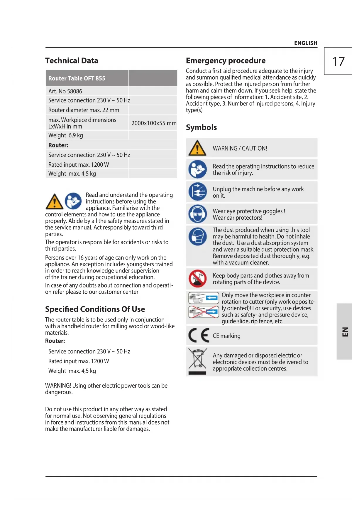
natural_image
3D rendering of a black rectangular metal plate with internal slots and a central hole (no text or symbols)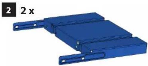
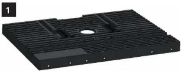
natural_image
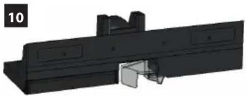
3D model of a blue mechanical component with two side slots and mounting brackets (no text or symbols)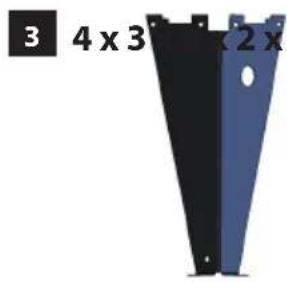
natural_image
Two black and blue metal trapezoidal panels with mounting holes, labeled '3 4 x 3' and '2 x' (no additional text or symbols)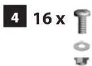

natural_image
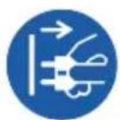
3D assembly diagram showing a blue mechanical component with threaded fasteners and bolted bolts, alongside three separate views of a bolt (no text or symbols)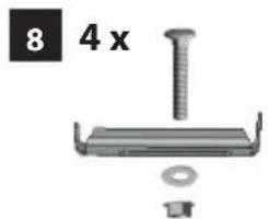
natural_image
Mechanical component with screw, nut, and washer (no text or symbols visible)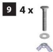
natural_image
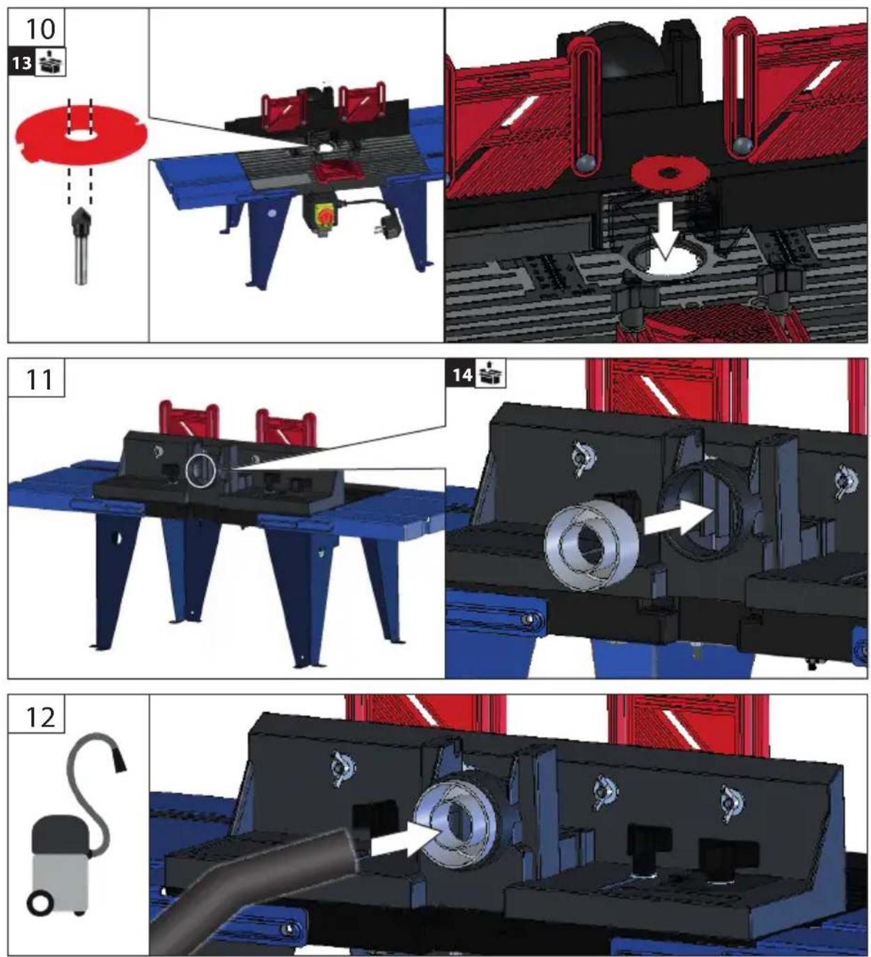
3D mechanical component diagram showing a housing with internal components and a highlighted part (no text or symbols)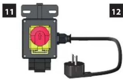
natural_image
3D diagram of a mechanical component with labeled parts 11 and 12, showing a red circular component connected to a black terminal block and a black plug (no text or symbols beyond labels)


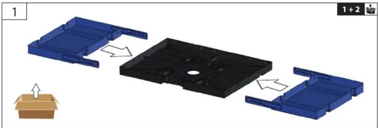
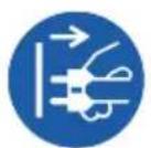
| DE | Montage | PL | Montaž |
| EN | Assembly | ||
| FR | Assemblage | ||
| IT | Montaggio | ||
| NL | Montage | ||
| CZ | Montáž | ||
| SK | Montáž | ||
| HU | Szerelés |
| DE | Inbetriebnahme | PL | Uruchomienie |
| EN | Starting-up the machine | ||
| FR | mise en service | ||
| IT | Messa in funzione | ||
| NL | Inbedrijfstelling | ||
| CZ | Uvedení do provozu | ||
| SK | Uvedenie do prevádzky | ||
| HU | Üzembe helyezés |
| DE | Betrieb | PL | Eksploatacja |
| EN | Operation | ||
| FR | Fonctionnement | ||
| IT | Esercizio | ||
| NL | Gebruik | ||
| CZ | Provoz | ||
| SK | Prevádzka | ||
| HU | Üzemeltetés |
| 1 | DE Montage PL Montaž |
| EN Assembly | |
| FR Assemblage | |
| IT Montaggio | |
| NL Montage | |
| CZ Montáž | |
| SK Montáž | |
| HU Szerelés |
natural_image
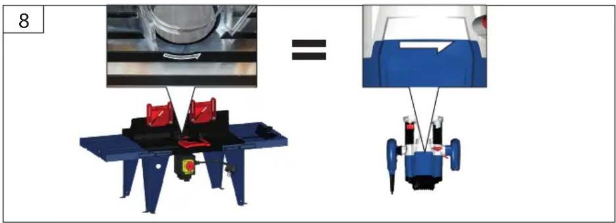
3D mechanical assembly diagram showing a blue plastic housing with internal components and directional arrows, no text or symbols present.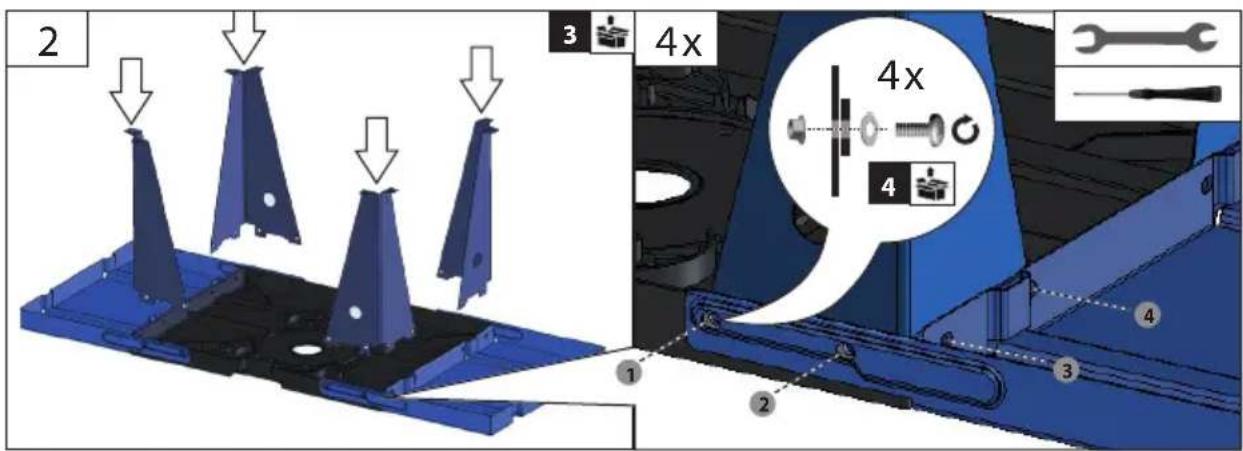
natural_image
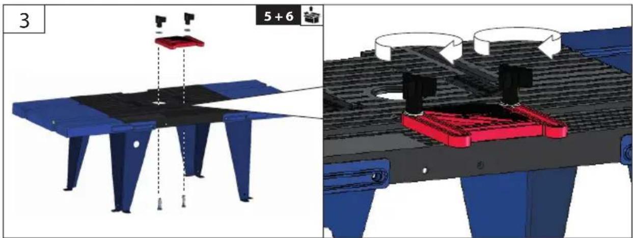
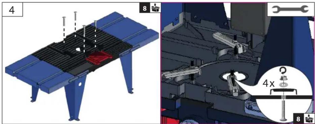
Technical illustration of a mechanical assembly with blue and red components, showing assembly steps (no text or symbols)PL Montaż
DE Montage
EN Assembly
FR Assemblage
IT Montaggio
NL Montage
CZ Montáž
SK Montáž
HU Szerelés


natural_image
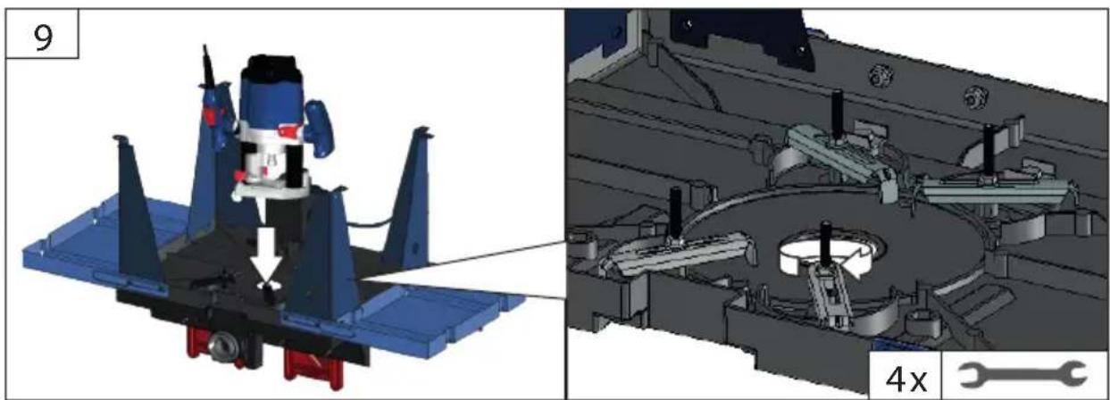
Technical illustration of a mechanical assembly with component details (no readable text or symbols)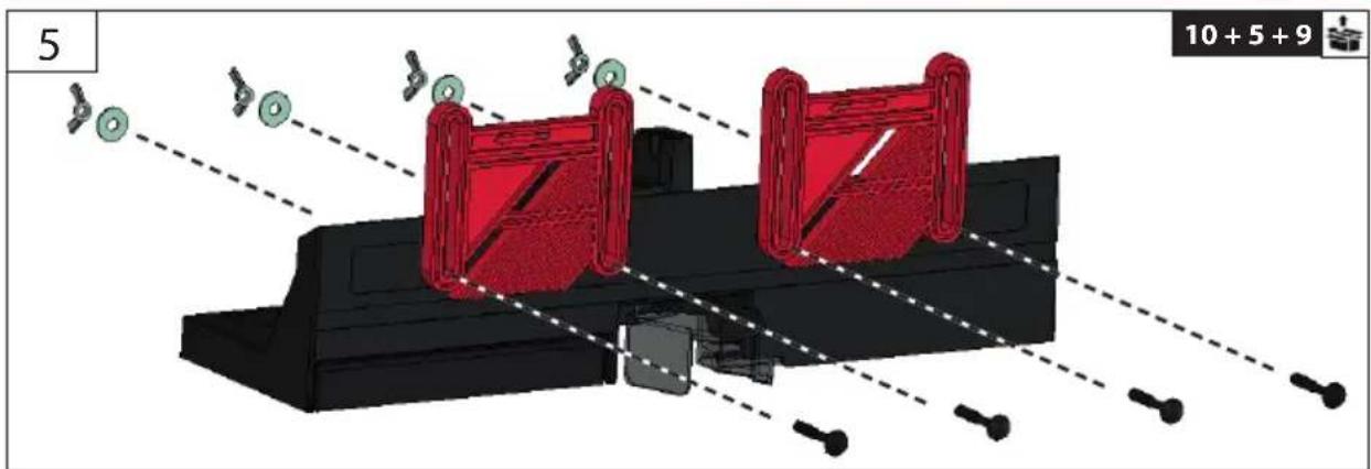
natural_image
3D mechanical assembly diagram showing red components and alignment lines (no text or symbols)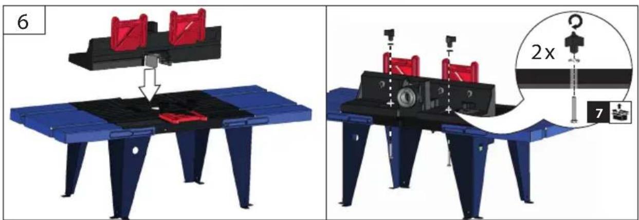
| 1 | DE Montage PL Montaž |
| EN Assembly | |
| FR Assemblage | |
| IT Montaggio | |
| NL Montage | |
| CZ Montáž | |
| SK Montáž | |
| HU Szerelés |
natural_image
3D mechanical assembly diagram showing a motor and gear assembly with no visible text or symbolsDE Montage
PL Montaż
EN Assembly
FR Assemblage
IT Montaggio
NL Montage
CZ Montáž
SK Montáž
HU Szerelés
 | DE | Inbetriebnahme | PL | Uruchomienie |
| EN | Starting-up the machine | |||
| FR | mise en service | |||
| IT | Messa in funzione | |||
| NL | Inbedrijfstelling | |||
| CZ | Uvedení do provozu | |||
| SK | Uvedenie do prevádzky | |||
| HU | Üzembe helyezés |

Not included in standard equipment.
natural_image
Abstract graphic with a black cross shape and a wooden grain outline (no text or symbols)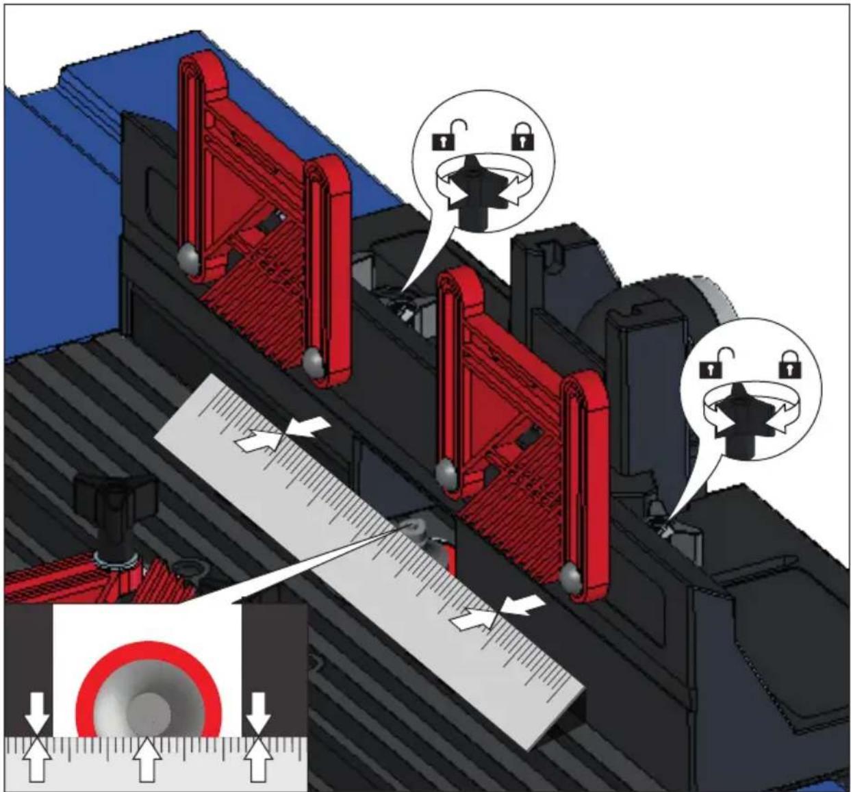
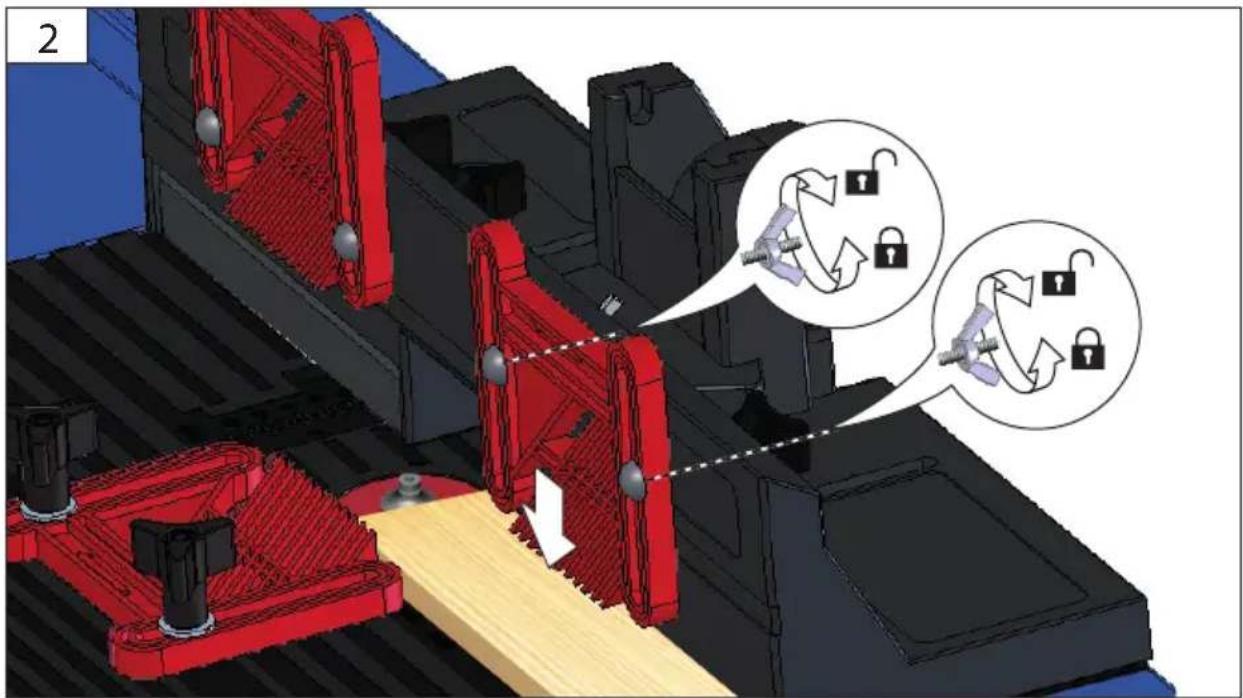
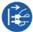
| 2 | DE | Inbetriebnahme | PL | Uruchomienie |
| EN | Starting-up the machine | |||
| FR | mise en service | |||
| IT | Messa in funzione | |||
| NL | Inbedrijfstelling | |||
| CZ | Uvedení do provozu | |||
| SK | Uvedenie do prevádzky | |||
| HU | Üzembe helyezés |
natural_image
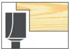
Simple line drawing of a mechanical component with a wooden block, no text or symbols present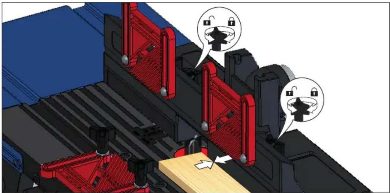
natural_image
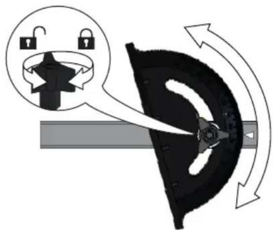
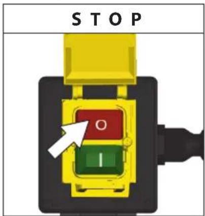
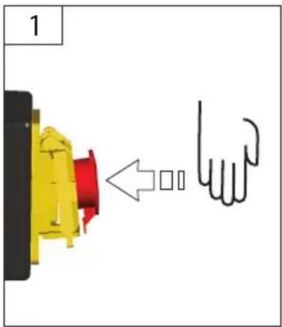
3D mechanical assembly diagram showing red components and lock icons, no readable text or symbols present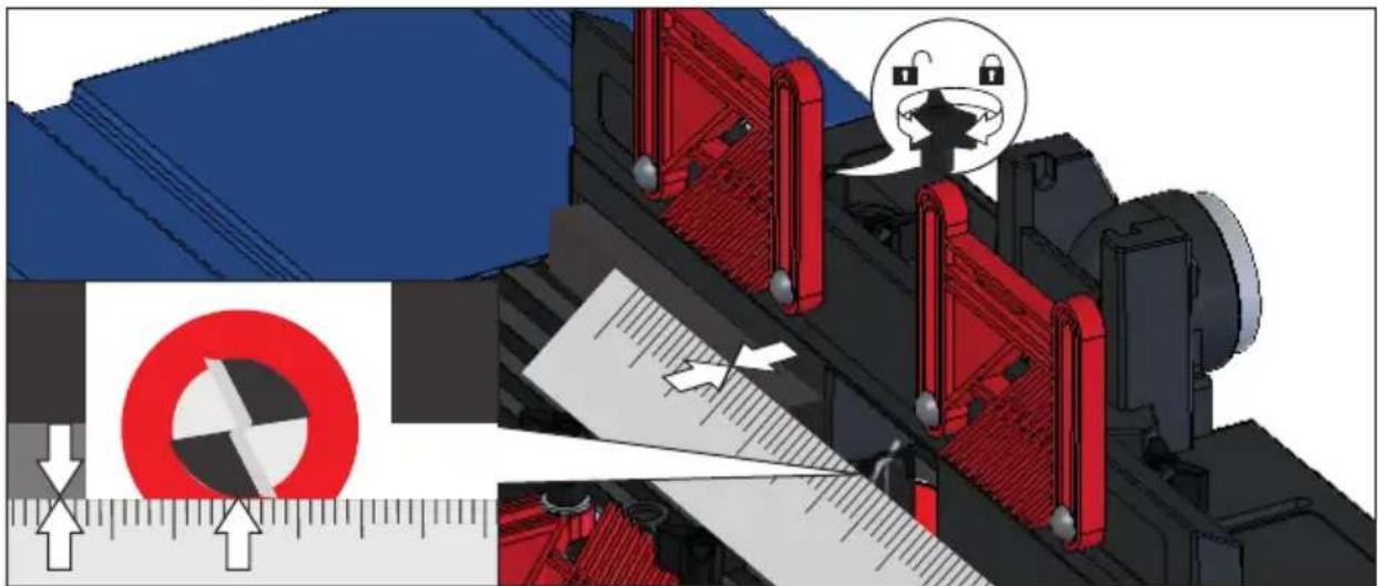
natural_image
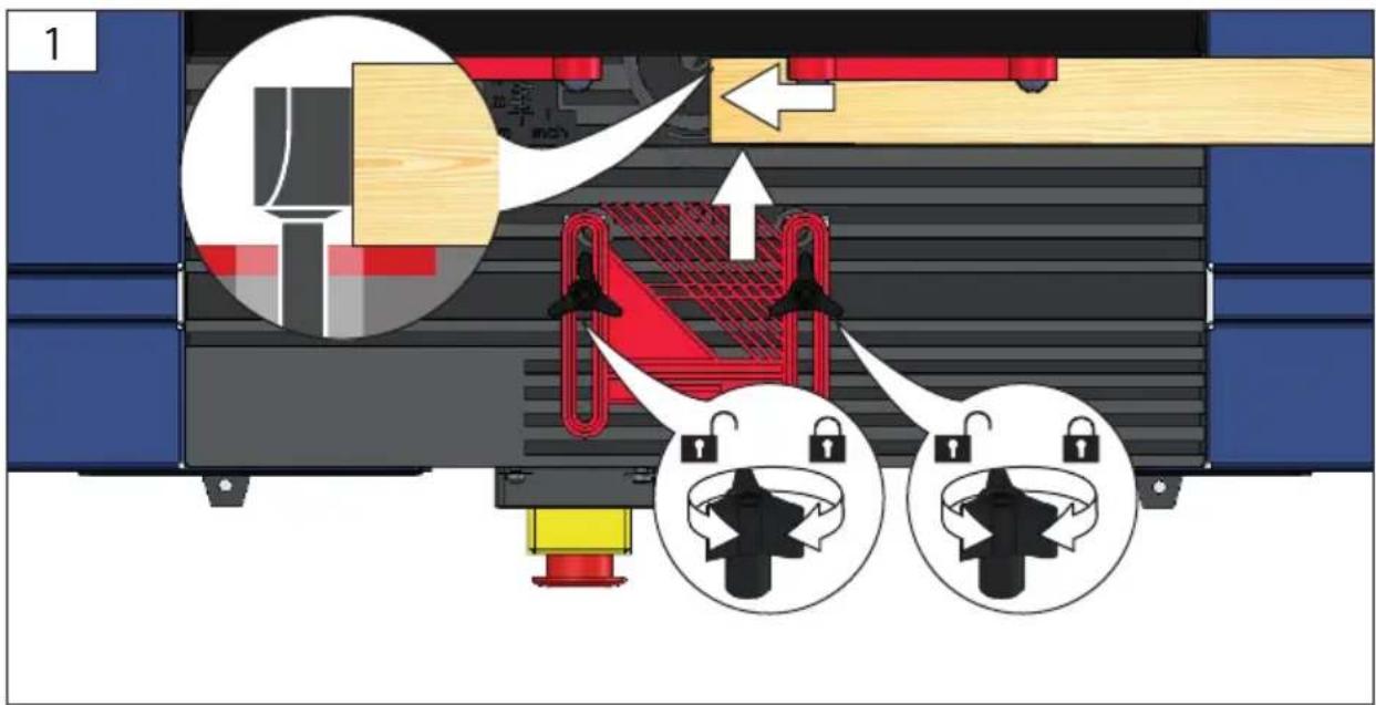
Mechanical assembly diagram showing a cutting machine with red components and directional arrows, no readable text or symbols present.DE Inbetriebnahme
PL Uruchomienie
EN Starting-up the machine
FR mise en service
IT Messa in funzione
NL Inbedrijfstelling
CZ Uvedení do provozu
SK Uvedenie do prevádzky
HU Üzembe helyezés
2
natural_image
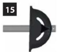
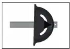
Simple diagram of a mechanical component with a central arrow and a vertical bar (no text or symbols)15
natural_image
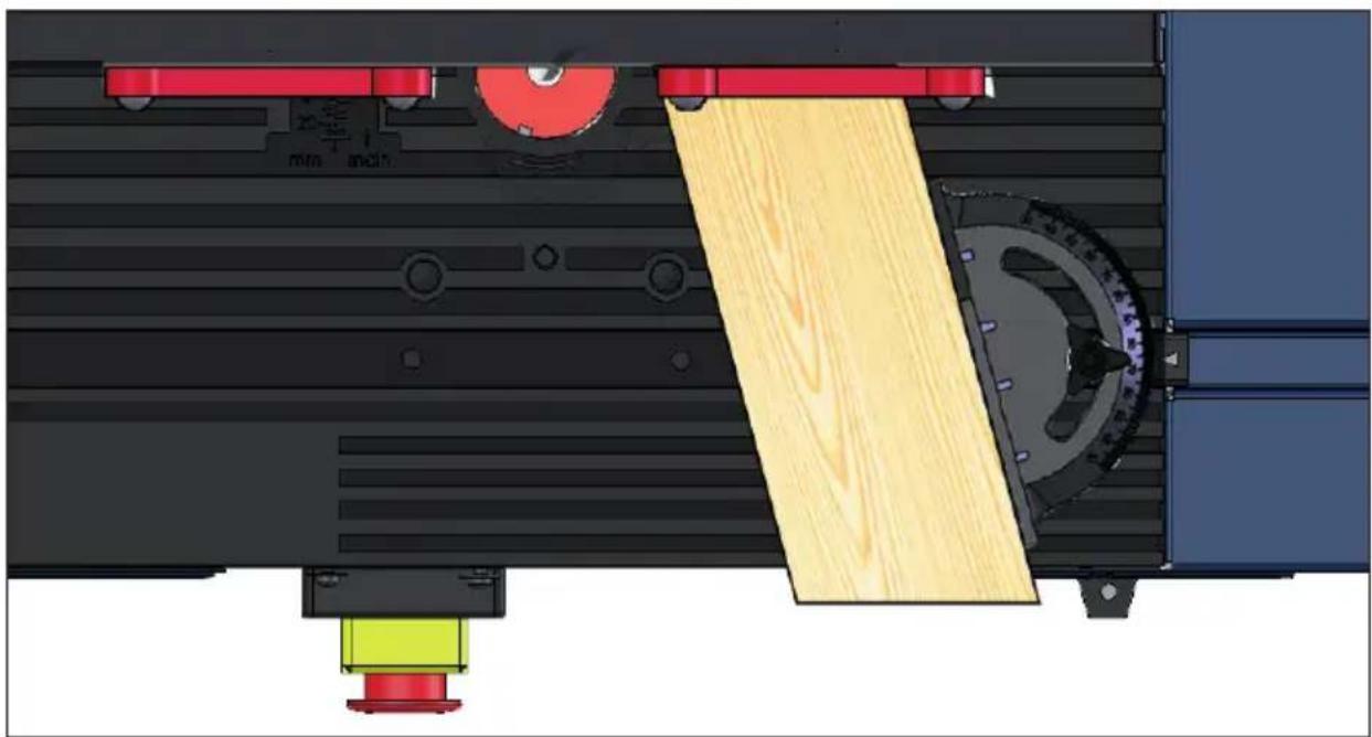
Technical diagram of a mechanical assembly with wooden components and labeled parts (no readable text or symbols)| DE | Inbetriebnahme | PL | Uruchomienie | |
| EN | Starting-up the machine | |||
| FR | mise en service | |||
| IT | Messa in funzione | |||
| NL | Inbedrijfstelling | |||
| CZ | Uvedení do provozu | |||
| SK | Uvedenie do prevádzky | |||
| HU | Üzembe helyezés |

DE Inbetriebnahme
PL Uruchomienie
EN Starting-up the machine
FR mise en service
IT Messa in funzione
NL Inbedrijfstelling
CZ Uvedení do provozu
SK Uvedenie do prevádzky
HU Üzembe helyezés
2
3

3
DE Betrieb
PL Eksploatacja
EN Operation
FR Fonctionnement
IT Esercizio
NL Gebruik
CZ Provoz
SK Prevádzka
HU Üzemeltetés


DE Betrieb
EN Operation
FR Fonctionnement
IT Esercizio
NL Gebruik
CZ Provoz
SK Prevádzka
HU Üzemeltetés
PL Eksploatacja


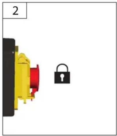
natural_image
Diagram showing a yellow and red component next to a black padlock, labeled '2' in top-left corner (no text or symbols on components)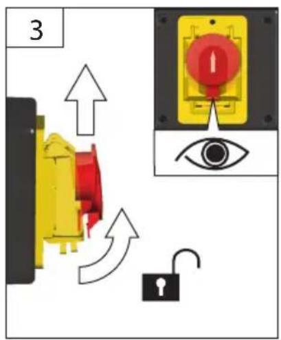
Technische Daten
| Router Table OFT 855 | |
| Art. No 58086 | |
| Service connection 230 V ~ 50 Hz | |
| Router diameter max. 22 mm | |
| max. Workpiece dimensions LxWxH in mm | 2000x100x55 mm |
| Weight 6,9 kg | |
| Router: | |
| Service connection 230 V ~ 50 Hz | |
| Rated input max. 1200 W | |
| Weight max. 4,5 kg | |


Read and understand the operating instructions before using the appliance. Familiarise with the
control elements and how to use the appliance properly. Abide by all the safety measures stated in the service manual. Act responsibly toward third parties.
The operator is responsible for accidents or risks to third parties.
Persons over 16 years of age can only work on the appliance. An exception includes youngsters trained in order to reach knowledge under supervision of the trainer during occupational education.
In case of any doubts about connection and operation refer please to our customer center
Specified Conditions Of Use
The router table is to be used only in conjunction with a handheld router for milling wood or wood-like materials.
Router:
Service connection 230 V \~ 50 Hz
Rated input max. 1200 W
Weight max. 4,5 kg
WARNING! Using other electric power tools can be dangerous.
Do not use this product in any other way as stated for normal use. Not observing general regulations in force and instructions from this manual does not make the manufacturer liable for damages.
Emergency procedure
Conduct a first-aid procedure adequate to the injury and summon qualified medical attendance as quickly as possible. Protect the injured person from further harm and calm them down. If you seek help, state the following pieces of information: 1. Accident site, 2.
Accident type, 3. Number of injured persons, 4. Injury type(s)
Symbols
 | WARNING / CAUTION! |
 | Read the operating instructions to reduce the risk of injury. |
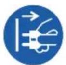
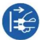
 | Unplug the machine before any work on it. |
 | Wear eye protective goggles !Wear ear protectors! |
 | The dust produced when using this tool may be harmful to health. Do not inhale the dust. Use a dust absorption system and wear a suitable dust protection mask. Remove deposited dust thoroughly, e.g. with a vacuum cleaner. |
 | Keep body parts and clothes away from rotating parts of the device. |
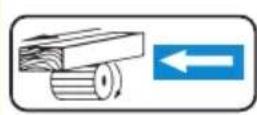
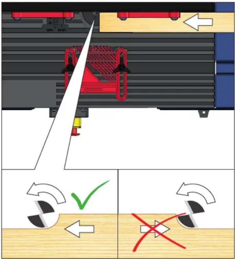
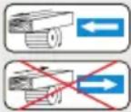 | Only move the workpiece in counter rotation to cutter (only work oppositely oriented)! For security, use devices such as safety- and pressure device, guide slide, rip fence, etc. |
 | CE marking |
 | Any damaged or disposed electric or electronic devices must be delivered to appropriate collection centres. |
General safety instructions for mounting fixtures

WARNING Read all safety instructions and actions supplied with the mounting fixture
or power tool. Failure to follow the warnings and instructions may result in electric shock, fire and/or serious injury.
Save all warnings and instructions for future reference.
Disconnect the plug from the socket and/or remove the battery before adjusting the equipment or replacing accessories. Some accidents are caused by power tools starting up unintentionally.
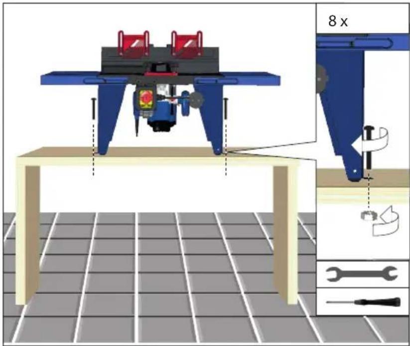
Before assembling the power tool, install the mounting device properly. Correct assembly is important in order to avoid the risk of collapsing.
Fasten the power tool securely to the mounting fixture before using it. If the power tool slips on the mounting fixture, this can lead to a loss of control.
Place the mounting fixture on a firm, level and horizontal surface. If the mounting fixture is unstable, the power tool cannot be steered smoothly and safely.
Do not overload the mounting fixture and do not use it as a ladder or scaffolding. Overloading or standing on the mounting fixture can cause the centre of gravity of the mounting fixture to move upwards and cause it to tip over.
Additional Safety and Working Instructions
Be sure to pay attention to the operating instructions for the attached router.
Always use the appropriate table feed rings relevant to the size of the milling tool.
Use protective equipment. Always wear safety glasses when working with the machine. The use of protective clothing is recommended, such as dust mask, protective gloves, sturdy non-slip footwear and ear defenders.
Wear ear protectors. Exposure to noise can cause hearing loss.
The dust produced when using this tool may be harmful to health. Do not inhale the dust. Use a dust absorption system and wear a suitable dust protection mask. Remove deposited dust thoroughly, e.g. with a vacuum cleaner.
Wear tight-fitting gloves at all times when handling sharp blades and saw blades,
Warning against thrown-off items
Always wear goggles when using the machine.
Warning against hand injury / bruising
Never reach into the danger area of the machine when it is running. Always use the protective shields on the machine.
Chips and splinters must not be removed while the machine is running.
Kickback is the sudden reaction caused by loss of control in guiding small workpieces. Pinching or snagging causes rapid stalling of the rotating wheel which in turn causes the uncontrolled power tool to be forced in the direction opposite of the wheel's rotation at the point of the binding.
Always use horizontal pressure devices when working on narrow workpieces. Uncontrolled tilting of the workpiece can cause a dangerous situation.
The device must not be used for arc milling.
Incorrect use of milling tools, workpieces and devices for workpiece guidance can lead to a dangerous situation. The operator must be adequately trained in the handling of the workpiece, the use, adjustment and operation of workpiece clamping devices and workpiece guiding devices as well as the selection of the milling tools.
Tools that are not regularly serviced can trigger uncontrollable situations. Use only sharp, well-serviced milling tools set according to the machine manufacturer's specifications.
Keep body parts and clothes away from rotating parts of the device.
Pull the plug out of the socket and/or remove the battery when the tool is not in use before you make machine settings or change accessories, such as the saw blade, drill bit or cutter. This safety measure prevents unintentional starting of the electric tool.
Keep your hands on the fence during milling. Use pressing devices (printing shoes) in conjunction with the fence whenever possible.
Missing lateral fences can cause kickback. When inserting the milling machine, use the rear and/or front lateral fences attached to the milling fence.
The cutter must be correctly clamped in the machine. Only move the workpiece in counter rotation to cutter (only work oppositely oriented)! For security, use devices such as safety- and pressure device, guide slide, rip fence, etc.
Set the speed to suit the material you wish to cut. Only use tools whose permitted speed is at least as high as the highest no-load speed of the machine.
Provide adequate support such as table extensions, saw horses, etc. for a workpiece that is wider or longer than the table top.
Put the router back to original position after usage (loosen clamping lever to secure cage).
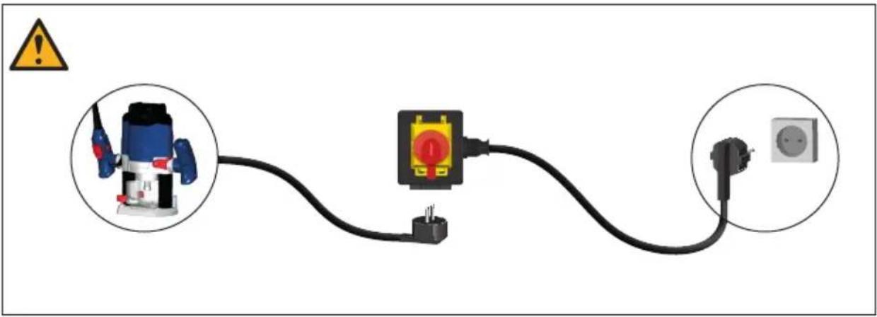
Mains Connection
Operation is only allowed with a safety switch against stray current (RCD max. stray current of 30mA).
Connect only to single-phase AC system voltage as indicated on the rating plate. It is also possible to connect to sockets without an earthing contact as the design conforms to safety class II.
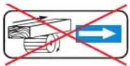
Only plug-in when machine is switched off.
Maintenance
⚠️ Unplug the machine before any work on it.
Repairs and works specified in these Instructions may only be performed by qualified authorised staff.
Use only original accessories and original spare parts.
Do not clean the plastics with solvents, flammable or toxic fluids. For cleaning, use a damp cloth only.
Caution! If the power cord of the appliance gets damaged, it must be replaced by the manufacturer or its customer service or a similarly qualified person to avoid danger.
Only a regularly maintained and treated appliance can serve as a satisfactory aid. Insufficient maintenance and care can lead to unforeseen accidents and injuries.
If necessary, a list of spare parts can be found at www.guede.com.
Service
Do you have any technical questions? Any claim? Do you need any spare parts or operating instructions?
We will quickly help you and without needles bureaucracy at our web pages at www.guede.com in the Servicing part. Please help us be able to help you. In order to identify your device in case of claim we need the serial No., product No. and year of production. All this data can be found on the type label.
Tel.: +49 (0) 79 04 / 700-360
Fax: +49 (0) 79 04 / 700-51999
E-Mail: support@ts.guede.com
Translation of the EC-Declaration of Conformity
We, hereby declare the conception and construction of the below mentioned appliances correspond - at the type of construction being launched - to appropriate basic safety and hygienic requirements of EC Directives.
In case of any change to the appliance not discussed with us the Declaration expires.


- OFT 855
- English TECHNICAL DATA | SAFETY INSTRUCTIONS | SPECIFIED CONDITIONS OF USE | EMERGENCY PROCEDURE | CHARGING EQUIPMENT | BATTERY | WORK INSTRUCTIONS | SYMBOLS | DISPOSAL | GUARANTEE | SERVICE \_\_\_\_ 17
- Français CARACTÉRISTIQUES TECHNIQUES | I NSTRUCTIONS DE SÉCURITÉ | UTILISATION CONFORME À LA DESTINATION | CONDUITE EN CAS D'URGENCE | DISPOSITIF DE CHARGE | BATTERIA | CONSIGNES DE TRAVAIL | SYMBOLES | LIQUIDATION | GARANTIE | SERVICE 20
- Specified Conditions Of Use
- Router:
- Emergency procedure
- General safety instructions for mounting fixtures
- WARNING Read all safety instructions and actions supplied with the mounting fixture
- Additional Safety and Working Instructions
- Be sure to pay attention to the operating instructions for the attached router.
- Wear tight-fitting gloves at all times when handling sharp blades and saw blades,
- Warning against thrown-off items
- Always wear goggles when using the machine.
- Keep body parts and clothes away from rotating parts of the device.
- Mains Connection
- Maintenance
- Service
- Translation of the EC-Declaration of Conformity
Brand : Güde
Model : OFT 855
Category : Milling table