
DSS100E - Switch D-LINK - Free user manual and instructions
Find the device manual for free DSS100E D-LINK in PDF.
| Product Type | 18-Port Unmanaged PoE Switch |
| Brand | D-Link |
| Model | DSS-100E-18P |
| Dimensions (L x W x H) | Approx. 440 x 200 x 44 mm (19-inch rack mountable) |
| Weight | Approx. 2 kg |
| Power Supply | 100-240 V AC, 50-60 Hz, max power consumption 230 W (PoE) |
| Ports | 16 RJ-45 10/100 Mbps PoE ports (ports 1-16), 1 RJ-45 10/100/1000 Mbps port (port 17), 1 combo RJ-45/SFP 10/100/1000 Mbps port (port 18) |
| Main Functions | Unmanaged switching, PoE power (IEEE 802.3af/at), DIP switches (Standard, Isolate, Extend) |
| LED Indicators | Power (green), PoE Max (red), Link/Activity/Speed (orange/green), PoE (orange) |
| Operating Temperature | 0 °C to 40 °C |
| Operating Humidity | 10% to 90% non-condensing |
| Mounting | On a flat surface (with rubber feet) or in a 19-inch rack (mounting kit included) |
| Grounding | Required before powering on; grounding screw and cable not provided |
| Package Contents | 1 x switch, 1 x power cord, 1 x rack mount kit, 1 x quick installation guide |
| Maintenance and Cleaning | Unplug the device, clean with a soft, dry cloth |
| Safety | Install in a cool, dry place away from electromagnetic sources, ensure at least 10 cm of ventilation on each side |
| Spare Parts and Repairability | Not specified; contact your local D-Link dealer if issues arise |
| General Information | Compliant with IEEE 802.3, 802.3u, 802.3ab, 802.3af/at; limited warranty (see D-Link website) |
Frequently Asked Questions - DSS100E D-LINK
User questions about DSS100E D-LINK
0 question about this device. Answer the ones you know or ask your own.
Ask a new question about this device
Download the instructions for your Switch in PDF format for free! Find your manual DSS100E - D-LINK and take your electronic device back in hand. On this page are published all the documents necessary for the use of your device. DSS100E by D-LINK.
USER MANUAL DSS100E D-LINK
Quick Installation Guide
This document will guide you through the basic installation process for your new D-Link 18-Port Unmanaged PoE Switch
DSS-100E-18P
This Quick Installation Guide gives you step-by-step instructions for setting up your DSS-100E-18P 18-Port Unmanaged PoE Switch. The model you have purchased may appear slightly different from the one shown in the illustrations. For more detailed information about the switch, please refer to the User Manual.
Package Contents
This DSS-100E-18P package should include the following items:
- 1 x DSS-100E-18P
- 1 x Power cord
- 1 × Rack mount kit and rubber feet
- 1 x Quick Installation Guide
If any of the above items are damaged or missing, please contact your local D-Link reseller.
Hardware Overview
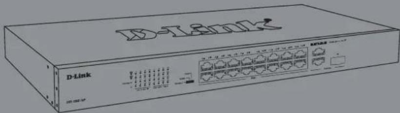
LED Indicators
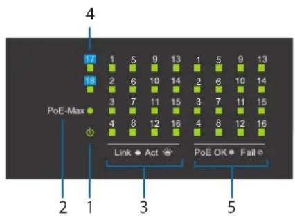
Figure 1
| # | LED Status | Description | n |
| 1 | Power | Solid green | The device is powered on. |
| Off The device is powered off. | |||
| 2 | PoE Max | Solid red | Indicates that the total PoE power output of the switch has exceeded the Guard Band threshold of 223 W, but is still below the total budget of 230 W. |
| Off | The total PoE power consumption is below the 223 W Guard Band threshold. | ||
| 3 | Link/Act/ Speed (Ports 1 to 16) | Solid amber | There is an active link negotiated at 10/100 Mbps on this port. |
| Blinking amber | There is traffic on the port at 10/100 Mbps. | ||
| Off No link | |||
Table1
| # | LED Status | Description | n |
| 4 | Link/Act/Speed(Ports 17to 18) | Solidgreen | There is an active link negotiated at10/100/1000 Mbps on this port. |
| Blinkinggreen | There is traffic on the port at 10/100/1000Mbps. | ||
| Off No link | |||
| 5 | PoE(Ports 1to 16) | Solidamber | The port is providing power to theconnected PoE-powered device. |
| Off | There is no PoE-powered deviceconnected to this port or PoE-powereddevice insert but failure occurs.(PSE can'tprovide power to PD due to PD error orpower budget is not enough.) |
Front Panel Connectors
Figure 2
Table 2
| # | Item Description | |
| 1 | Ports 1 ~16 | 10/100 Mbps PoE-capable ports for connecting Ethernet devices and PoE-powered devices. |
| 2 | Port 17 | 10/100/1000 Mbps Ethernet uplink port for connecting to another switch using an Ethernet cable. |
| 3 | Port 18 | 10/100/1000 Mbps GbE/SFP combo uplink port for connecting to another switch using an Ethernet cable or installing a compatible SFP transceiver. |
Rear Panel Connectors
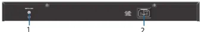
Figure 3
Table 3
| # Item Description | |
| 1 Switch GND This is used to connect the switch to ground. | |
| 2 Power Input | This is used to connect the power cable to the switch. |
DIP Switches
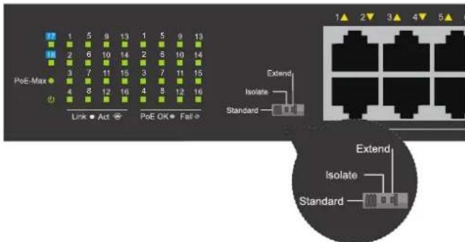
The DIP switches on the front panel allow easy configuration of the advanced features of the DSS-100E-18P
Table 4
| DIP Switch | Function Controlled | Default |
| Standard | Switch all ports can communicate with each other port and work as a common Unmanaged Switch. *1 to 16 port supports Power over Ethernet and transmit data at 10/100 Mbps.** 1 to 8 port supports port priority to optimize port cache. | On |
| Isolate | 1 to 16 port can't communicate with each other, but each of them can communicate with port 17 and 18. | Off |
| Extend | The data rate of 9 to 16 port is limited to 10Mbps, whereas the maximum transmission distance of the port is increased to 250 meters. | Off |
Hardware Installation
Before You Begin
Observe the following precautions to help prevent shutdowns, equipment failures, and personal injury:
- Install the DSS-100E-18P in a cool and dry place. Refer to the technical specifications in the user manual for the acceptable operating temperature and humidity ranges.
- Install the switch in a site free from strong electromagnetic sources, vibration, dust, and direct sunlight.
- Leave at least 10cm of space to the left and right-hand side of the switch for ventilation.
- Visually inspect the power connector and make sure that it is fully secured to the power cord.
- Do not stack any devices on top of the switch.
Using the Switch on a Flat Surface
The included rubber pads can be placed on the bottom of the device to prevent it from damaging the surface it is placed on.
-
Remove the rubber pads from the adhesive strip.
-
Stick one pad on each corner on the bottom panel of the switch.
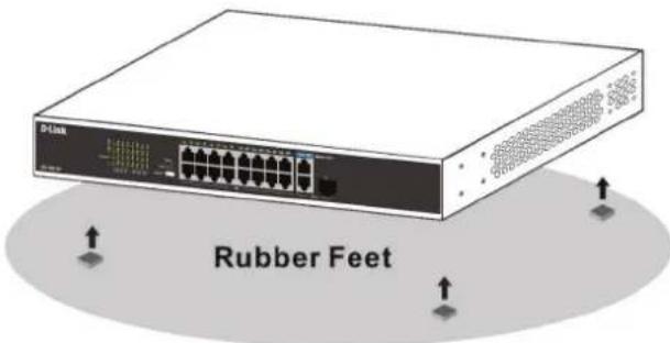
Figure 4
Mounting the Switch in a Rack
The DSS-100E-18P can be mounted into a standard 19^ server rack.
- Attach the included mounting brackets to the sides of the switch and secure them using the provided screws.
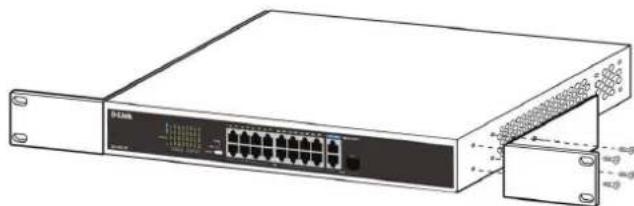
Figure 5
- Install the switch into the rack.
- Use the screws that were provided with the rack to secure the switch to the rack.
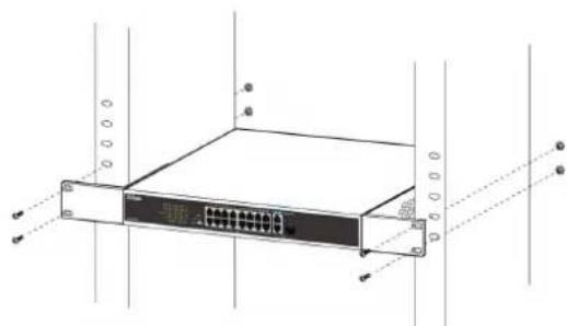
Figure 6
Grounding the Switch
This step must be completed before powering on the switch.
Required tools and equipment for grounding
- Grounding screw (included) and one M4x6 (metric) pan-head screw (not included).
- Grounding cable (not included). The grounding cable should be sized according to local and national installation requirements. Depending on the power supply and system, a 12 to 6 AWG copper conductor is required for installation. Commercially available 6 AWG wire is recommended. The length of the cable depends on the proximity of the switch to proper grounding facilities.
- A screwdriver (not included).
Note: Verify that the system is powered off.
- Remove the grounding screw from the back of the device and place the #8 terminal lug ring of the grounding cable on top of the grounding screw opening.
- Insert the grounding screw back into the screw opening and use a screwdriver to tighten the grounding screw.
- Attach the terminal lug ring at the other end of the grounding cable to an appropriate grounding source.
- Verify that the connection between the grounding connector on the switch and the grounding source is secure.
Powering On the Switch
- Connect the power cord to the power connector on the switch.
- Plug the other end of the power cord into a nearby power socket.
Connecting to the Network
The switch can be integrated into the network through one of the following connection methods:
Switch to End Node or Powered Device
Use a standard Ethernet cable to connect the switch to PCs with an 10/100/1000 Mbps RJ-45 interface, or connect and power remote IEEE 802.3af/atcompliant devices, such as IP cameras or IP phones using PoE.
Switch to Hub or Switch
Connect the switch to another switch or hub using the RJ-45 or SFP uplink ports.
Switch to Server
Connect the switch to a network backbone or network server using the RJ-45 or SFP uplink ports.
Additional Information
For additional support, please refer to the user manual, or visit eu.dlink.com/support which will direct you to your local D-Link support website.