
BDG4327DS - Kitchen faucet Concept - Free user manual and instructions
Find the device manual for free BDG4327DS Concept in PDF.
| Product Type | Kitchen Faucet |
| Brand | Concept |
| Model | BDG4327DS |
| Body Material | Chrome-plated brass with scratch-resistant coating |
| Cartridge | High quality ceramic |
| Rotation | 360° |
| Total Height | 35 cm (approx) |
| Net Weight | 1.5 kg (approx) |
| Supply | Cold and hot water via flexible hoses |
| Connection | 3/8" inlet with threaded reducer included |
| Installation | On sink, fixation by nut and mounting parts |
| Cleaning | Neutral products, soapy solution, vinegar for limescale |
| Maintenance | Regular drying, occasional polishing for chrome surfaces |
| Warranty | In accordance with legal warranty of conformity |
| Spare parts | Cartridge, aerator, seals, handle, flexible hoses |
| Repairability | Possible replacement of cartridge and seals |
| Package contents | Faucet body, handle, flexible hoses, mounting parts, aerator |
Frequently Asked Questions - BDG4327DS Concept
User questions about BDG4327DS Concept
0 question about this device. Answer the ones you know or ask your own.
Ask a new question about this device
Download the instructions for your Kitchen faucet in PDF format for free! Find your manual BDG4327DS - Concept and take your electronic device back in hand. On this page are published all the documents necessary for the use of your device. BDG4327DS by Concept.
USER MANUAL BDG4327DS Concept
natural_image
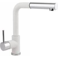
Line drawing of a simple kitchen faucet with handle and base (no text or symbols)Dřezová baterie / Drezová batéria Bateria kuchenna / Sink faucet / Küchenarmatur / Grifo de fregadero / Robinet d'évier / Mosogató csaptelep / Batteria per lavello da cucina
PODĚKOVÁNÍ
BDC3334, BDG3334BC, BDG3334BE, BDG3334WH

| Číslo Položka |
| 1 Perlátor |
| 2 Hlava výpustu |
| 3 Spojovacie diely |
| 4 Výpust |
| 5 Spojovacie diely |
| 6 Te o batérie |
| 7 Podstavec |
| 8 Kartuša |
| 9 Matica |
| 10 Skrutkovací uzáver |
| 11 Držadlo |
| 12 Upevňovacie diely |
| 13 Hadica |
BDC3334, BDG3334BC, BDG3334BE, BDG3334WH
BDC3334, BDG3334BC, BDG3334BE, BDG3334WH
Thank you for purchasing a Concept product. We wish you much joy with your new appliance every day you use it. Please read the instruction manual carefully before initial use. To refer to this manual any time you need to, we recommend you to keep it in a safe place. And please pass it to any future owner of the appliance. Follow the recommendations in the manual and then use the new product successfully.
TABLE OF CONTENTS
- Important safety information
• Technical specifications - Cleaning and maintenance
- Faucet installation
- Warranty
IMPORTANT SAFETY INFORMATION
When maintaining the faucet, take into account its surface finish and use cleaning agents which are suitable for the surface. Never use cleaning agents containing chlorine or alcohol and if you work with such agents close to the faucet, avoid contact.
Although the surface of the faucets is durable, avoid mechanical damage by sharp objects such as scratches with a kitchen knife.
TECHNICAL SPECIFICATIONS
Minimum water pressure: (0.5 bar)
Maximum water pressure: (10 bar)
Maximum hot water temperature: 80 °C
Recommended hot water temperature: 70 °C
CLEANING AND MAINTENANCE
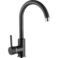
Concept sink faucets combine practical and high-quality design. Inside each faucet, there is a high-quality ceramic cartridge that forms the main body of the faucet. The surface of the faucet is coated with scratch-resistant technology. At the same time, it was developed to perfectly match the design of Concept granite sinks.
Clean the faucet regularly with neutral detergents that do not contain abrasive particles; soap solution is sufficient. After cleaning, rinse the surface with water and dry. Remove larger dirt and scale deposits with vinegar solution, or with detergent containing vinegar. After use, dry the faucet surface with a soft cloth. Regular drying protects the faucet from unwanted scale deposits.
EN
Polish faucets with chrome finish from time to time with a special agent for stainless steel or chrome finish. That will remove stains and restore the chrome surface gloss.
Treat faucets with granite surface once in a while with water and milk for granite sinks. Rinse the surface with warm water and dry with a soft cloth. Remove lime deposits around the strainer with vinegar solution or acetic cleaner.
Daily and regular care extends their lifespan.
FAUCET INSTALLATION
Please follow the following instruction during product installation: The warranty does not cover damages caused by incorrect installation.
Before product installation, make sure it is not damaged in any way.
The product should be installed by a professional qualified to install faucets.
Thanks to the fact that each faucet body can be rotated 360 °, you can install the handle on both the right and left side.
Installation
- Shut off the hot and cold water supply.
- Unscrew the aerator to prevent it from clogging the first time you use the faucet.
- Position the faucet body on the sink with the fixing parts. Connect the water hoses and tighten by hand. Do not tighten with tools or brute force, the threads on valves or hoses could be damaged.
- If necessary, screw a 3/8" threaded adapter onto both hoses.
- Screw the hoses to the water supply and open the water supply. Leave the faucet in a closed position where no water flows and check all connections for leaks. If you need to make additional tightening of joints, be sure to close the water supply.
- If all joints are tight, let hot and cold water run, first for a shorter period of time. Then install the aerator that you first dismantled and put the faucet back into operation.
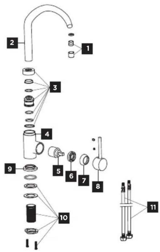
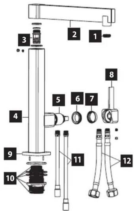
Description of individual parts of the product BDC6529, BDG6529BC
| Number Item |
| 1 Aerator |
| 2 Spout |
| 3 Body |
| 4 Base |
| 5 Cartridge |
| 6 Connect nut |
| 7 Cap |
| 8 Handle |
| 9 Fixing parts |
| 10 Inlet hose |
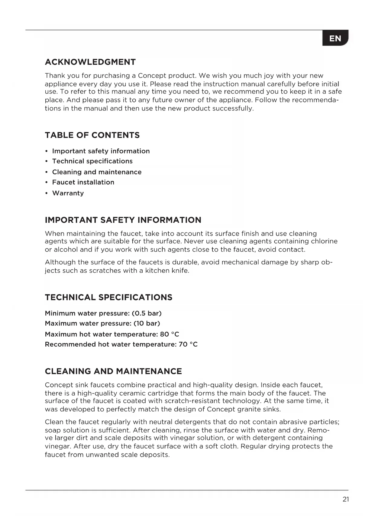
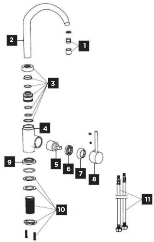
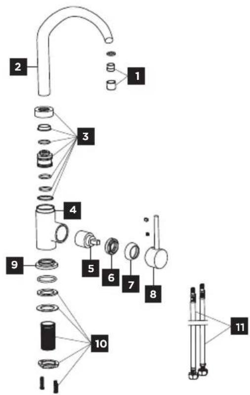
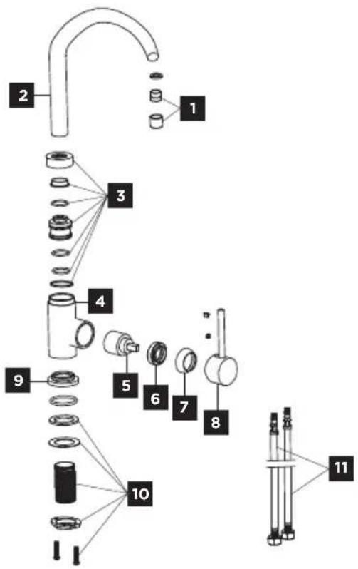
Description of individual parts of the product
BDC4327, BDG4327BC, BDG4327BE, BDG4327WH, BDG4327DS
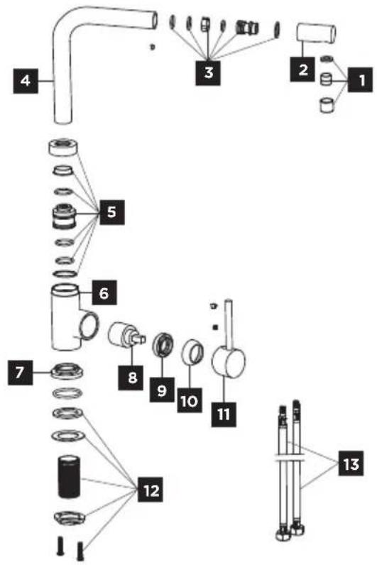
| Number Item |
| 1 Aerator |
| 2 Spout head |
| 3 Connecting parts |
| 4 Spout |
| 5 Connecting parts |
| 6 Body |
| 7 Base |
| 8 Cartridge |
| 9 Connect nut |
| 10 Cap |
| 11 Handle |
| 12 Fixing parts |
| 13 Inlet hose |
EN
Description of individual parts of the product BDC3334, BDG3334BC, BDG3334BE, BDG3334WH

| Number Item | |
| 1 Aerator | |
| 2 Spout | |
| 3 Connecting parts | |
| 4 Body | |
| 5 Cartridge | |
| 6 Connect nut | |
| 7 Cap | |
| 8 Handle | |
| 9 Base | |
| 10 Fixing parts | |
| 11 Inlet hose |
Description of individual parts of the product BDC5327, BDC5327BC
| Number Item | |
| 1 Aerator | |
| 2 Spout | |
| 3 Connecting parts | |
| 4 Body | |
| 5 Cap | |
| 6 Bonnect nut | |
| 7 Cap | |
| 8 Handle | |
| 9 Base | |
| 10 to Fixing part | |
| 11 Inlet hose | |
| 12 Inlet tube |
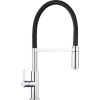
Description of individual parts of the product
BDC4527, BDG4527BC, BDG4527BE, BDG4527WH, BDG4527DG
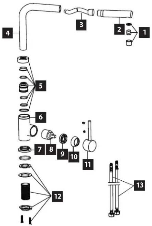
| Number Item | |
| 1 Aerator | |
| 2 Shower head | |
| 3 Hose | |
| 4 Spout | |
| 5 Connecting parts | |
| 6 Body | |
| 7 Button | |
| 8 Cartidge | |
| 9 Bonnect nut | |
| 10 Cap | |
| 11 Handle | |
| 12 Fixing parts | |
| 13 Inlet hose |
EN
Description of individual parts of the product BDC7547
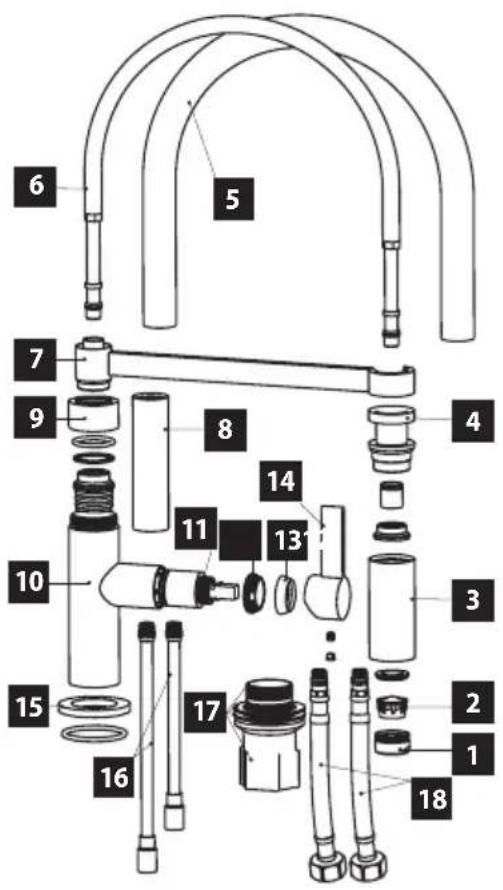
| Number Item | |
| 1 Aerator shell | |
| 2 Aerator | |
| 3 Pull out head | |
| 4 Hose connector | |
| 5 Silicone hose | |
| 6 Connecting hose | |
| 7 | Pull out head holder |
| 8 Conector | |
| 9 Body cap | |
| 10 Body | |
| 11 Cartridge | |
| 12 Bonnet nut | |
| 13 Cap | |
| 14 Handle | |
| 15 Button | |
| 16 Inlet tube | |
| 17 Fixing part | |
| 18 Inlet hoses | |
WARRANTY
The manufacturer is responsible for manufacturing and material defects during the warranty period specified by the manufacturer. In the event that such defects occur, please return the sink to the seller with enclosed documents of its acquisition. Keep these documents throughout the warranty period.
The warranty does not cover defects caused by incorrect assembly or maintenance. Damages from failure to follow the manufacturer's instructions are not covered by the warranty.
DANKSAGUNG
BDC3334, BDG3334BC, BDG3334BE, BDG3334WH
BDC3334, BDG3334BC, BDG3334BE, BDG3334WH

BDC3334, BDG3334BC, BDG3334BE, BDG3334WH

BDC3334, BDG3334BC, BDG3334BE, BDG3334WH
Numéro Article
W: www.my-concept.pl

Jindřich Valenta — Concept
Vysokomýtská 1800,
565 01 Choceň, Czech Republic
T: +420 465 471 400
E: info@my-concept.cz
W: www.my-concept.cz
Brand : Concept
Model : BDG4327DS
Category : Kitchen faucet