
MTT 990 - Turntable MAGNAT - Free user manual and instructions
Find the device manual for free MTT 990 MAGNAT in PDF.
| Brand | Magnat |
| Model | MTT 990 |
| Product type | Direct Drive Turntable |
| Dimensions (W x H x D) - cover closed | 450 x 162 x 365 mm |
| Dimensions (W x H x D) - cover open | 450 x 412 x 412 mm |
| Turntable weight | 1.9 kg |
| Power supply | Mains 230 V / 115 V (selectable), 50/60 Hz |
| Standby power consumption | < 0.5 W |
| Rotation speeds | 33 1/3, 45, 78 rpm |
| Drive | Quartz-controlled direct drive |
| Wow and flutter (33 1/3 rpm) | < 0.06 % |
| Signal-to-noise ratio (A-weighted) | > 72 dB |
| Starting torque | > 2.5 kgf·cm |
| Platter diameter | 305 mm |
| Tonearm length | 10" (254 mm) |
| Supported cartridge weight | 3 to 10 g |
| Tracking force adjustment range | 0 to 3.5 g |
| Anti-skating adjustment | Same as tracking force |
| Tonearm height adjustment | 6 mm |
| Supplied accessories | Platter, felt mat, counterweight, headshell, 45 rpm adapter, dust cover with hinges, RCA audio cable, power cable |
| Maintenance | Dry soft cloth, avoid solvents |
| Safety | Do not open the housing, refer all servicing to qualified personnel |
Frequently Asked Questions - MTT 990 MAGNAT
User questions about MTT 990 MAGNAT
0 question about this device. Answer the ones you know or ask your own.
Ask a new question about this device
Download the instructions for your Turntable in PDF format for free! Find your manual MTT 990 - MAGNAT and take your electronic device back in hand. On this page are published all the documents necessary for the use of your device. MTT 990 by MAGNAT.
USER MANUAL MTT 990 MAGNAT
At the end of the product's useful life, please dispose of it at appropriate collection points provided in your country.
Fig. 7
natural_image
Technical line drawing of a mechanical assembly with no visible text or symbolsDear MAGNAT Customer,
Thank you very much for choosing MAGNAT! You have made an excellent choice. Please study the instructions and information below carefully before using your new device.
IMPORTANT SAFETY NOTICE
Please read through the instruction manual carefully before starting to use the device. This manual contains important information concerning operation and safety aspects. It is imperative you observe all of the information. Keep the manual in a safe location.
- WARNING NOTICES: All of the warning symbols on the device, accessories and in the instruction manual itself must be adhered to.
- EXPOSURE TO HEAT: Only operate the device and accessories in a temperature range from 10^ to 40^ .
- The device should not be positionedFet near heat sources (heaters, ovens, radiant heaters, naked flames, etc.). When setting up close to amplifier a minimum distance of 10 cm must be maintained.
No naked flame sources, such as lighted candles, should be placed on the device.
Pay attention to a sufficient ventilation of the device. The device may not be covered, e.g. by drapes, curtains. Maintain a distance of 20 cm to walls.
- EFFECT OF MOISTURE: The device should not be exposed to dripping or splash water. Neither should it be used to support vases or other containers filled with liquid. Do not expose the device to water or high levels of humidity. There is a danger of electric shock. In the event of contact with moisture or liquids the device should be disconnected from the mains immediately..
- FOREIGN MATERIAL: Ensure that no foreign material enters through the device openings and into the interior. This could trigger short circuits and even result in electric shock and fire.
- CLEANING: Please use a soft, dry cloth with no cleaning agents, sprays or chemical solvents, as these could damage the surfaces.
- ELECTRICAL CONNECTION: Please note the voltage levels on the information signs. The device should only be operated with the voltage and frequency values specified on the signs.
- LIGHTNING PROTECTION/PREVENTIVE MEASURES: If the device is not going to be used for a prolonged period (e.g. when on holiday), it should be disconnected from the mains by removing the plug. The device should also be disconnected from the mains in the event of a thunderstorm. Doing this will prevent damage caused by lightning and overvoltage.
- MAINS CABLE: The mains cable must always be suitable for operation and it should only ever be laid out in a manner that prevents it from being trodden on. It should not be pinched by objects either, as this can damage the cable. When using plugs and power strips it must be ensured that the cable is not kinked at the point where it emerges from the socket. Do not connect or remove the mains cable with damp hands.
The mains plug is used as the disconnecting device. Disconnecting devices shall remain readily operable.
- OVERLOAD: Sockets, power strips and extension cables should not be overloaded. If an overload occurs, there is a risk of electric shock and fire.
- SETTING UP: Please read the installation instructions.
- The device should only be positioned or mounted on a solid surface and not on moving base frames, otherwise there is a risk of injury.
- Only use attachments/accessories specified by the manufacturer.
- Batteries (battery pack or batteries installed) shall not be exposed to excessive heat, such as sunshine, fire and the like.
- CAUTION: Danger of explosion if battery is incorrectly replaced. Replace only with the same or equivalent type.
DAMAGE THAT MUST BE RECTIFIED BY A SPECIALIST:
If any of the following damage occurs, disconnect the device from the mains immediately and contact a specialist to conduct the repair work:
- The device should not continue to be operated if there is visible damage to the mains cable. A damaged cable should not be repaired, but must be replaced.
- Damage to the mains socket at the device.
- If moisture or water has entered the device or foreign objects have fallen into the device.
- If the device has fallen and the housing is damaged.
- If the device does not work properly, even though all of the information in the instruction manual has been observed.
Only those subsequent alterations approved by the manufacturer may be conducted.
Only original spare parts should be used for repair.
After conducting any repairs the safety of device should be checked to ensure it is functioning correctly and safely.
Repairs must always be conducted by qualified specialists, as you might otherwise be exposed to dangerous high voltage levels or other hazards.

The triangle with a lightning symbol warns the user that high voltage is used within the device which can result in electric shock.

The triangle with an exclamation mark informs the user that important operating and maintenance instructions (repair) are contained in the accompanying instruction manual, which must be observed.
Do not open! Risk of electric shock!
CAUTION: In order to avoid electric shock do not open the speaker housing/mains adapters or remove the covers. The user is not to conduct any repairs him/herself. Repairs should only be conducted by qualified technicians! Do not use any sockets or extension cables that do not fully accommodate the plug of the device.
INSTRUCTIONS FOR DISPOSAL
In accordance with European Directive 2012/19/EU all electrical and electronic appliances must be disposed of separately via local collection points. Please observe the local regulations and do not dispose of your old appliances with normal household waste.
USE AS DIRECTED
This device is designed for indoor use only.
INCLUDED PARTS
Please unpack the device and the accessories carefully and check if everything is complete:
a. Platter 1x
b. Felt mat for platter 1x
c. Counterweight 1x
d. Headshell 1x (for type art.no. 149 701/149 701C)
e. Headshell incl. cartridge 1x (for type art.no. 149 700/149 700C)
f. Adaptor for 45rpm records 1x
g. Dust cover 1x
h. Hinges for dust cover 2x
i. Audio cable, stereo RCA connectors at both ends, with ground line
j. Power cord
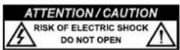
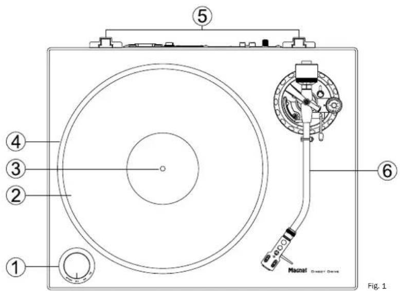
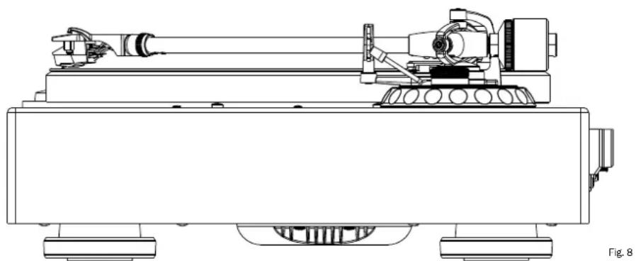
PARTS AND CONTROLS OF THE DEVICE
1) Power switch / speed selector
2) Platter mat (felt)
3) Center spindle
4) Platter
5) Brackets for dust cover hinges
6) Tone arm
7) Counterweight
8) Stylus force adjustment dial
9) Tone arm lift
10) Tone arm lift height adjustment screw
11) Tone arm rest
12) Tone arm lock
13) Tone arm
14) Knurled nut for locking the headshell
15) Headshell
16) Cue lever
17) Anti-skate control dial
18) Tone arm height adjustment lock
19) Tone arm height adjustment dial
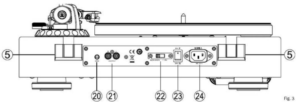
20) Clamp screw for ground line
21) RCA stereo audio outputs
22) Mains voltage selector
23) Power switch
24) Mains connector
ASSEMBLY
Make sure to place the device on a clean and sturdy surface.
1. Mounting the platter:
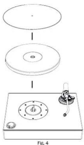
Carefully lower the platter (4) with the smooth side up onto the center spindle (3). Please make sure that you do not damage the delicate tone arm.
To improve the decoupling of the record from unwanted vibration, please put the felt mat (2) onto the platter.
2. Mounting the headshell:
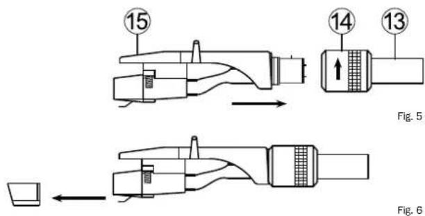
Slide the connector joint of the headshell (15) onto the front end of the tone arm (13) and lock it by carefully turning the knurled nut towards the platter until hand-tight.
Note: Type art.no. 149 701/149 701C comes without a cartridge. We recommend to perform the assembly of the cartridge of your choice at this point. Please refer to the mounting instructions given by the cartridge manufacturer.
Type art.no. 149 700/149 700C comes with a high-quality cartridge that has already been mounted and adjusted.
The supplied cartridge is equipped with a stylus protection cover which has to be removed for operation and some adjustment tasks. Please carefully pull off the protection cover to the front (fig. 6). After use of the turntable, we recommend to put the protection cover on the cartridge again.
3. Attaching the counterweight
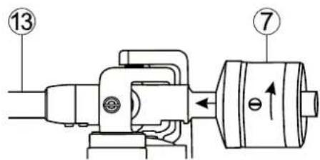
Fig. 7
Attach the counterweight of the tone arm (7) by screwing it onto the rear end of the tone arm as shown. Turn the weight until the center line on top of the tone arm is only just visible.
4. Horizontal adjustment of the turntable
Place the device in its intended position. The surface must be sturdy and plane. There should be no amplifiers, speakers, radios or TV sets close to it.
Now the device needs to be accurately aligned horizontally. The height of the four feet can be adjusted by turning them.
TONE ARM ADJUSTMENT
Attention: The following steps have to be carried out with utmost care. As the tone arm mechanism is very sensitive, you should never handle any parts of the tone arm with too much force.
Please be extremely careful with the cartridge and in particular with the stylus. Avoid touching the stylus at all. Defective styluses must be exchanged immediately as they worsen the playback quality and can damage the record.
1. Adjusting the tone arm balance
Before adjusting the stylus force, the tone arm balance needs to be adjusted.
Please proceed as follows:
- Set the anti-skate control dial (17) to 0.
- Remove the stylus cover of the cartridge (fig. 6).
- Unlock the tone arm lock (12) by sliding the locking lever to the right.
- Adjust the tone arm counterweight (7) by turning it until the tone arm hovers horizontally and stops tilting upwards or downwards by itself.
Attention: Please do this very carefully and make sure that neither the cartridge nor the stylus bump into the platter or the turntable body and get damaged. While turning the counterweight, make sure to hold the tone arm with the other hand.
2. Adjusting the stylus force
After balancing the tone arm, you should now adjust the stylus force.
Please proceed as follows:
- Turn the stylus force adjustment dial (8) at the front end of the counterweight unit its '0' mark is centric with the center line of the tone arm. Please make sure to only turn the adjustment dial itself, not the counterweight.
- Now turn the counterweight (7) together with the adjustment dial (8) towards the platter until the desired value on the dial (stylus force in grams) matches the center line on top of the tone arm.
Type art.no. 149 700/149 700C: Recommended stylus force of the supplied cartridge Audio Technica AT 95E: 2.0g
Type art.no. 149 701/149 701C: Please check the recommended stylus force in the technical specifications of the cartridge of your choice.
3. Adjusting the anti-skate
When playing a record, a force is generated that pulls the tone arm towards the center of the record. A correct anti-skate adjustment compensates that force.
Please proceed as follows:
- Turn the anti-skate control dial (17) to the same value as the stylus force. This automatically generates the correct anti-skate value.
4. Adjusting the tone arm height
natural_image
Technical line drawing of a mechanical device with cylindrical components and wheels (no text or symbols)Type art.no. 149 700/149 700CC: The arm height has already been adjusted correctly for the pre-assembled cartridge and the use of the supplied felt mat.
Type art.no. 149 701/149 701C: Depending on the model of cartridge used, it might be necessary to adjust the height of the tone arm. Please proceed as follows:
- Unlock the height adjustment by turning the lock lever (18) counter-clockwise.
- Put a record on the turntable, raise the tone arm lift with its cue lever (16) and lead the tone arm towards the record.
- Without the stylus protector in place, carefully lower the tone arm lift by pulling the cue lever downwards (16) until the stylus touches the record.
- Please carefully adjust tone arm height so that the tone arm is precisely horizontal and parallel to the record. To do this, simply turn the tone arm height adjustment dial (19) at the tone arm base.
Attention: During the adjustment, you should lift the cartridge stylus up with the tone arm lift in order to avoid damage to the stylus.
• After having completed the adjustment, lock the height adjustment by turning the lock lever (18) clockwise.
5. Adjusting the arm lift height
When the arm lift is raised, the stylus tip should be approx. 10-15mm above the record. If an adjustment is necessary, please proceed as follows:
- Raise the tone arm lift by pushing the cue lever (16) upwards and carefully guide the tone arm onto the tone arm rest (11).
- Adjust the height of the lift by turning the adjustment screw (10) either counter-clockwise (increase lift height) or clockwise (decrease lift height). To do this, you need a small cross-slot screwdriver (not included).
Important: During the adjustment, the tone arm lift (9) needs to be gently pushed downwards.
- Double check the adjusted height by guiding the tone arm onto the raised lift above the record.
CONNECTION AND MOUNTING OF THE DUST COVER
1. Connecting the amplifier
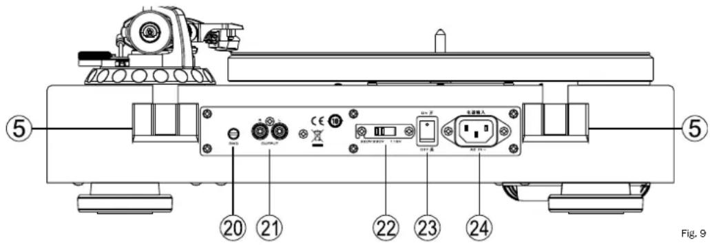
Please use the supplied RCA cable (i) to connect the stereo audio outputs (21) of the turntable to the input of a phono pre-amplifier or a dedicated phono input of an amplifier. Please pay special attention to correct channel assignment: The left channel is marked in white (RCA socket and RCA plug), the right channel in red. Additionally, the ground line has to be connected to the turntable and to the phono amplifier. To do this, carefully loosen the clamp screw (20), fix the fork shoe of the cable under the screw and tighten it again.
Attention: If your amplifier does not have a phono input, you need to use a separate phono pre-amplifier between your turntable and your amplifier.
Type art.no. 149 700/149 700C: For the supplied cartridge Audio Technica AT 95E, a phono MM (Moving Magnet) input is required.
2. Connecting to the mains supply
Plug the supplied power cord (j) into the mains connector (24) and plug the other end into a power outlet.
Attention: The factory setting for the mains voltage selector (22) is 230V for use in Europe. If the turntable is set to 115V and connected to a 230V power grid, it will inevitably be destroyed!
3. Mounting the dust cover
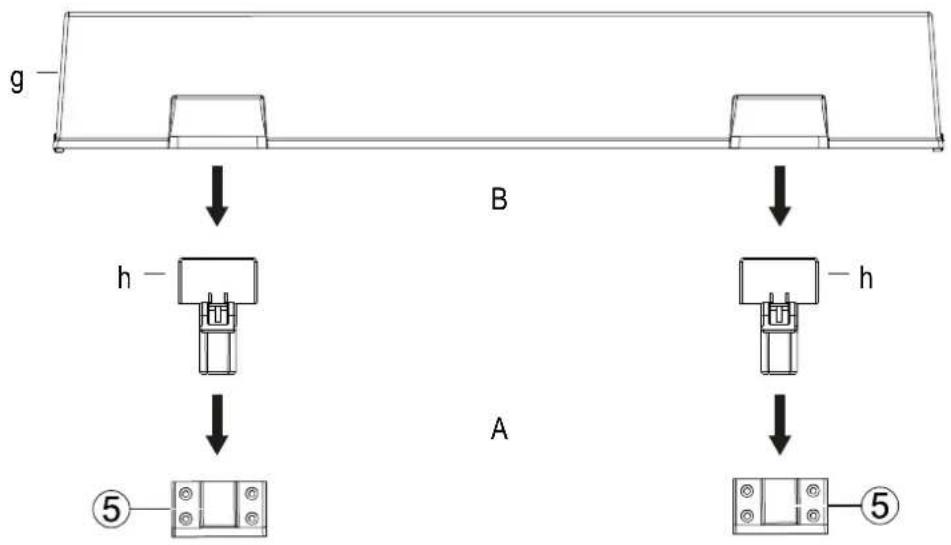
Fig. 10
Take the hinges (h) for the dust cover out of their packaging and insert their narrow side into the slots at the rear of the turntable as shown. Now carefully slide the dust cover (g) onto the wide side of the hinges.
Attention: Please open and close the dust cover slowly and carefully during playback (lowered stylus) in order to avoid mechanical shock.
OPERATION
1. Playing a record
Switch on the turntable by bringing the power switch (23) on the back of the turntable to the 'ON' position.
Power on the connected amplifier and choose the input which the turntable is connected to (usually PHONO). The volume of the amplifier should be set low.
Put a record on the turntable. Use the supplied adapter (f) if the record has a large hole in the middle (f).
Choose the appropriate playback speed with the speed selector (1). The platter starts to rotate.
Remove the stylus protection from the cartridge (fig. 6).
Remove the tone arm lock (12) and move the cue lever (16) upwards to raise the tone arm lift.
Carefully guide the tone arm over the lead-in groove of the record. A small handle has been mounted on the right of the headshell for easier handling.
Lower the tone arm by moving the cue lever (16) downwards.
Adjust the desired volume on the amplifier.
2. Pausing playback
The playback can be paused at any time by lifting the tone arm up with help of the arm lift (9). To do this, simply raise the cue lever (16). The tone arm can then be guided to whatever point on the record and be put down again by lowering the cue lever (16) again.
Attention: Before raising or lowering the tone arm lift, the playback volume should be reduced!
3. Stopping playback
This turntable is not equipped with a limit stop. When the record is played and the stylus entered the lead-out groove, the tone arm lift should soon be raised manually in order to avoid unnecessary wear of the stylus.
Carefully put the tone arm back onto the tone arm rest (11) and lower the arm lift (9) with the cue lever (16).
Turn the speed selector (1) to the 'STOP' position.
Attention: If the device is not used for a prolonged period of time, the tone arm should be secured with the tone arm lock (12).
4. Standby mode
This device is provided with an automatic standby mode which is automatically activated after 15 minutes of non-use (speed adjustment dial set to 'STOP'). In standby mode, the power consumption of the turntable is reduced to less than 0.5 W to avoid unnecessary power consumption. The standby mode will be interrupted automatically as soon as the speed selector (1) is set to one of the three speeds.
If the device is not used for a prolonged period of time, the power switch (23) on the back of the device should be set to the 'OFF' position.
CLEANING AND CARE
The lacquered surface is best cleaned with a mild household cleaner. On no account use furniture polish or similar products on these surfaces.
TECHNIAL SPECIFICATIONS
High end direct drive turntable
Speeds 33 1/3, 45, 78 rpm
Wow & flutter < 0.06% (33 1/3 rpm)
Signal/noise ratio (A-weighted) > 72 dB
Signal/noise ratio (unweighted) > 65 dB
Torque > 2.5 kgf cm
Platter diameter 305 mm
Platter weight (net) 1.9 kg
Tonearm length 10"
For cartridges weighing 3 - 10 g
For cartridges with a dynamic compliance of Medium - medium-stiff
Overhang 16.8 mm
Offset angle 21.4°
Weight of headshell 9 g
Adjustment range of tracking force 0 - 35 mN / 0 - 3.5 g
Adjustment range of antiscating Analogue to tracking force
VTA (height adjustment)
6 mm
Cabinet surface
Piano Schwarz / piano black
Dimensions (wxhxd)
Cover closed: 450 x 162 x 365 mm
Cover open: 450 x 412 x 412 mm
Weight
10.7 kg
Très cher client,
Fig. 7
natural_image
Technical line drawing of a mechanical device with articulated arms and wheels (no text or symbols)Vitesses 33 1/3, 45, 78 tours/min
natural_image
Technical line drawing of a mechanical device with cylindrical components and wheels (no text or symbols)Fig. 7
natural_image
Technical line drawing of a mechanical assembly with no visible text or symbolsFig. 7
natural_image
Technical line drawing of a mechanical device with cylindrical components and mounting base (no text or symbols)Fig. 4
Fig. 7
natural_image
Technical line drawing of a mechanical assembly with no visible text or symbolsCongratulations! You have made a wise selection in becoming the owner of a MAGNAT HiFi equipment.
The equipments are checked and tested continuously during the entire production process. In case you have problems with your MAGNAT HiFi equipment, kindly observe the following:
- The warranty period commences with the purchase of the component and is applicable only to the original owner.
- During the warranty period we will rectify any defects due to faulty material or workmanship by replacing or repairing the defective part at our discretion. Further claims, and in particular those for price reduction, cancellation of sale, compensation for damages or subsequential damages, are excluded.
- Unauthorized tampering with the equipment will invalidate this warranty.
- Consult your authorized dealer first, if warranty service is needed. Should it prove necessary to return the component to the factory, please insure that • the component is packed in original factory packing in good condition • your enclose your receipt as proof of purchase.
- Excluded from the warranty are: • Illuminates • Valves • Batteries • Wear parts • Shipping damages, either readily apparent or concealed (claims for such damages must be lodged immediately with forwarding agent, the railway express office or post office). • Scratches in cases, metal components, front panels, etc. (You must notify your dealer directly of such defects within three days of purchase.) • Defects caused by incorrect installation or connection, by operation errors (see operating instructions), by overloading or external force. • Equipments which have been repaired incorrectly or modified or where the case has been opened by persons other than us. • Consequential damages to other equipments. • Reimbursement of cools, without our prior consent, when repairing damages by third parties.
F
Toutes nos félicitations!