
MFG 185 - Fridge VESTFROST - Free user manual and instructions
Find the device manual for free MFG 185 VESTFROST in PDF.
| Product type | Refrigerator |
| Brand | Vestfrost |
| Model | MFG 185 |
| Power supply | 220-240 V / 50 Hz |
| Recommended fuse | 10-13 A |
| Climate class | SN (10-32 °C), N (16-32 °C), ST (16-38 °C), T (16-43 °C) |
| Refrigerant | Flammable (type according to rating plate) |
| Defrosting | Automatic |
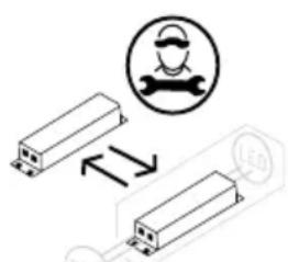
| Interior lighting | LED (class 1, replaceable by a professional) |
| Temperature control | Electronic with digital display |
| Number of shelves | Several (glass) |
| Adjustable feet | Yes (front) |
| Installation | Freestanding or built-in (observe ventilation space) |
| Minimum room volume | 1 m³ per 8 g of refrigerant (to avoid flammable mixture) |
| Cleaning | Warm water (max 65 °C) and mild detergent |
| Door seal maintenance | Clean with clear water regularly |
| Maintenance | Reserved for qualified personnel |
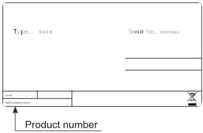
| Spare parts | Order with type, serial number (on rating plate) |
| Warranty | Not covered in case of misuse or modification |
| Disposal | Do not dispose with household waste (follow local regulations) |
Frequently Asked Questions - MFG 185 VESTFROST
User questions about MFG 185 VESTFROST
0 question about this device. Answer the ones you know or ask your own.
Ask a new question about this device
Download the instructions for your Fridge in PDF format for free! Find your manual MFG 185 - VESTFROST and take your electronic device back in hand. On this page are published all the documents necessary for the use of your device. MFG 185 by VESTFROST.
USER MANUAL MFG 185 VESTFROST
natural_image
Simple line drawing of a cabinet or enclosure with diagonal lines and a minus symbol at the bottom (no text or labels)
MFG 185 - Full Glas
GB Instructions for use
As the appliance contains a flammable refrigerant, it is essential to ensure that the refrigerant pipes are not damaged.
The quantity and type of the refrigerant used in your appliance is indicated on the rating plate.
Standard EN378 specifies that the room in which you install your appliance must have a volume of 1 m^3 per 8 g of hydrocarbon refrigerant used in the appliances. This is to avoid the formation of flammable gas/air mixtures in the room where the appliance is located in the event of a leak in the refrigerant circuit.
WARNING:
Keep ventilation openings in the appliance's cabinet or in the built-in structure clear of obstruction.
WARNING:
Do not use other mechanical devices or other means to accelerate the defrosting process than those recommended by the manufacturer.
WARNING:
Do not damage the refrigerant system.
WARNING:
Do not use electrical appliances inside the refrigerated storage compartment, unless they are of a type recommended by the manufacturer.
WARNING:
Do not expose the appliance to rain.
WARNING:
This appliance may be used by children over the age of 8 years old and by persons with reduced physical, sensory or mental capabilities or by persons with a lack of experience or knowledge if they are supervised or are instructed by a person responsible for their safety how to use the appliance safely and have understood the associated hazards.
WARNING:
Children must not play with, on, or around the appliance.
WARNING:
Children must not clean the
appliance or carry out general maintenance unless they are at least 8 years old and are being supervised.
WARNING:
Do not store explosives, such as aerosol cans with flammable propellants in the unit.
WARNING:
Danger risk of fire or explosion if flammable refrigerant are used. To be repaired only by trained personnel.
WARNING:
When positioning the appliance, ensure the power cord is not trapped or damaged.
WARNING:
Do not locate multiple portable socket-outlets or portable power supplies at the rear of the appliance.
- Always keep the keys in a separate place and out of reach of children.
- Before servicing or cleaning the appliance, unplug the appliance from the mains or disconnect the electrical power supply.
- Relevant for Australia: Supply cord fitted with a plug complies with AS/NZS 3112.
- If the supply cord is damaged, it must be replaced by the manufacturer, its service agent, or similarly qualified persons inorder to avoid a hazard.
- Frost formation on the interior evaporator wall and upper parts is a natural phenomenon. Therefore, the appliance should be defrosted during normal cleaning or maintenance.
- Please note that changes to the appliance construction will cancel all warranty and product liability.
- Do not use extension cords.
- Do not cover shelves with aluminium foil or any other material which may prevent air circulation;
CLASS 1 LED PRODUCT
Contents
Warning 2
Electrical connection....4
Get to know your bottle cooler....5
Before use 6
Installation 6
Operation and function 9
Fault finding....10
Defrosting, cleaning and maintenance .....11
Warranty, spare parts and service....12
Disposal....13
CE Declaration of conformity......Page A
Replaceable light source by a professional
Replaceable control gear by a professional
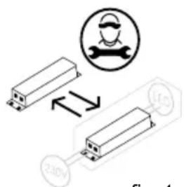
fig.1
Electrical connection
Wiring and connections in power supply systems must be all applicable (local and national) electrical codes. Consult these codes lengths and sizes prior to cabinet installation.
This device complies with relevant EU directives including Low Voltage Directive 2014/35/EU and Electromagnetic Compatibility Directive 2014/30/EU
The socket should be freely accessible.
Connect the appliance only to 220 / 240 V / 50Hz alternating current via a correctly installed earthed socket.
The socket must be fused with a 10-13 A fuse.
If the appliance is to be operated in a non-European country, check on the rating plate whether the indicated voltage and current type correspond to the values of your mains supply.
Information regarding voltage, current or power are given on the rating plate
The power cord may be replaced by a technician only.
The rating plate provides various technical information as well as type and serial number.
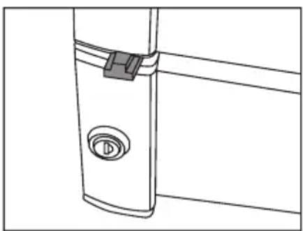
Get to know your bottle cooler
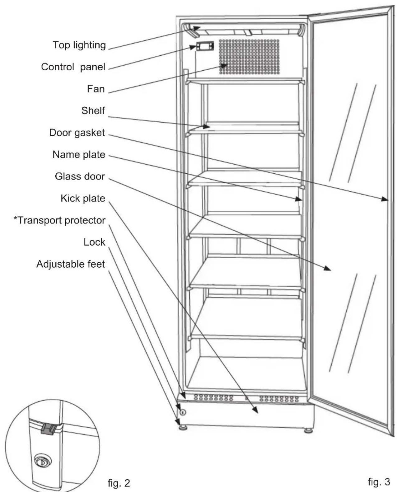
*Transport protector
Before use
Before operating your new appliance, please read the following instructions carefully as they contain important information on safety, installation, operation and maintenance.
Keep the instructions for future reference. On receipt, check to ensure that the appliance has not been damaged during transport.
Transport damage should be reported to the local distributor before the appliance is put to use.
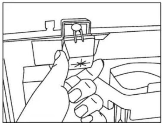
Remove the transport protector before the appliance is put to use. (fig 2) Hang it on one of the shelves as it can be used to adjust the door.
If the appliance has to be moved, use the protector
Remove the packaging. Clean the inside of the cabinet using warm water with a mild detergent. Rinse with clean water and dry thoroughly (see cleaning instructions). Use a soft cloth.
If during transport the appliance has been laid down, or if it has been stored in cold surroundings (colder than +5°C), it must be allowed to stabilise in an upright position for at least an hour before being switched on.
Note: If the appliance is to be laid down, the door must face upwards and the appliance must be enclosed in the original packaging1
natural_image
Line drawing of a mechanical component with a circular feature and a handle (no text or symbols)fig. 4
Installation
Placement
For safety and operational reasons, the appliance must not be installed outdoors.
The appliance should be placed on a level surface in a dry, well ventilated room (max. 75% relative air humidity). Never place the appliance close to sources of heat such as cookers or radiators, and avoid placing it in direct sunlight.
Ambient temperature
The climate class is stated on the name-plate (see page 12). This specifies the optimum ambient temperature. Wine coolers with winter position, however, function at ambient temperatures as low as 5°C.
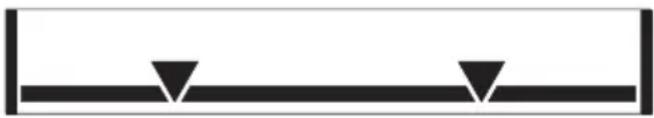
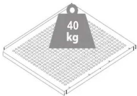
Load limit line
natural_image
Simple black line diagram with two downward-pointing triangles on a horizontal bar (no text or symbols)Permanently marked boundary line denoting the limit of the loading surface. If there is no load line sticker, please take the top of unit as standard.
| Climate class Optimum room temperature | |
| SN +10 °C to +32 °C | |
| N +16 °C to +32 °C | |
| ST +16 °C to +38 °C | |
| T +16 °C to +43 °C |
The surface on which the appliance is to be placed must be level. Do not use a frame or similar.
The appliance can be installed as a free-standing unit against a wall, built into a closet or lined up with other appliances.
It is important that the appliance be well ventilated and that air can circulate unhindered above, below and around it.
The Figures below illustrate how the necessary air circulation around the appliance can be ensured (g 5-8).
g. 6
g. 7
g. 5
g. 8
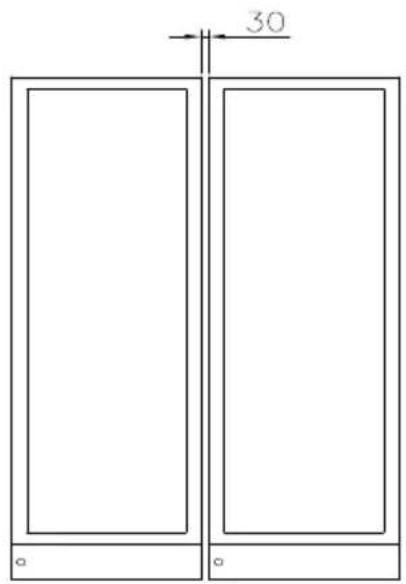
fig. 9
A "Side by Side" kit can be ordered (fig 9)
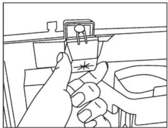
The distance pieces on the rear of the appliance ensure sufficient air circulation. Fit the two caps supplied with the appliance as shown in fig. 10
natural_image
Line drawing of a hand holding a plastic clip attached to a door panel (no text or symbols)fig. 10
Setting up
It is important that the appliance be absolutely level. It can be levelled by screwing the adjustable feet at the front of the appliance up or down (fig 11).
Use a spirit level to check that the appliance is absolutely level sideways.

natural_image
Technical line drawing of a mechanical assembly with a threaded component and base (no text or symbols)fig. 11
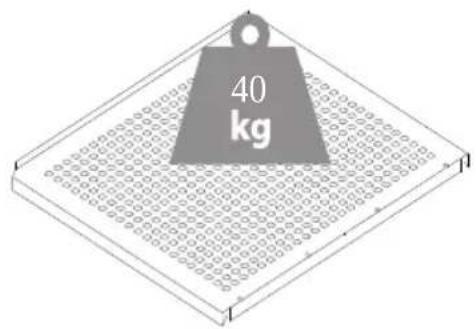
fig. 12
Operation and function
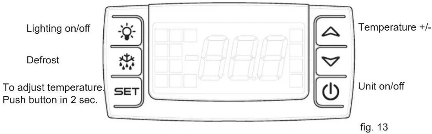
Electronic controls
The electronic controls ensure that the set temperature is maintained.
Following any power failure, the temperature settings are automatically recalled.
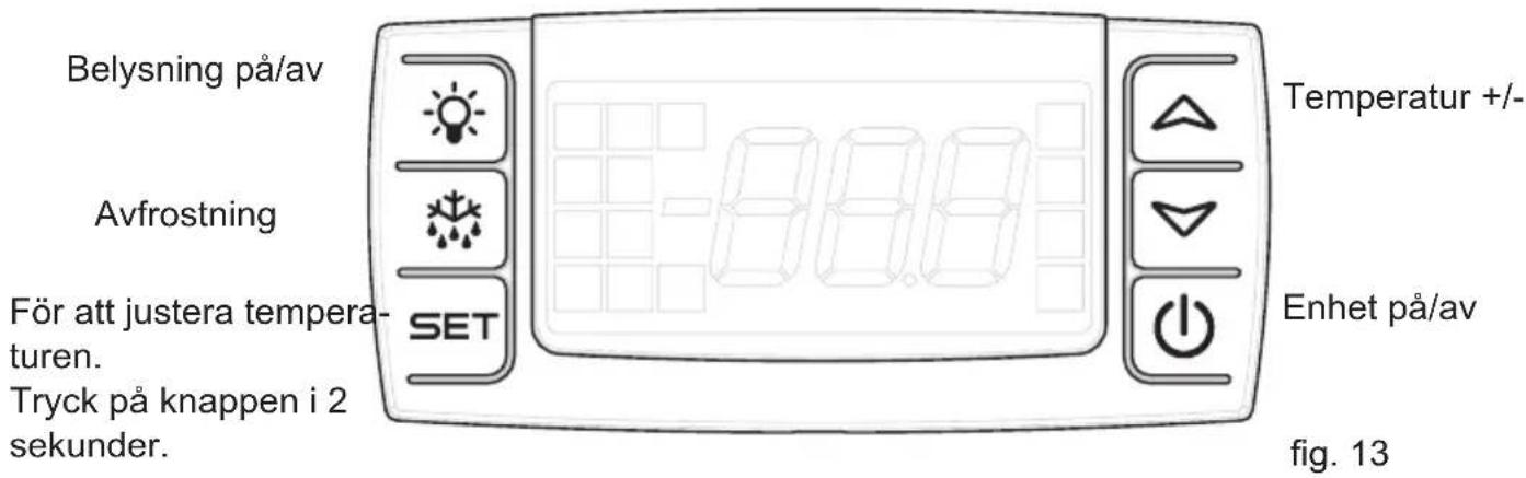
Manual defrosting
If there is a need for manual defrosting, push the Defrost botton for more than 2 second and a manual defrost will start.
After 30 min. the electronic control will return to normal mode
Temperature display
The display shows the actual temperature in the cabinet, and indicates that power is connected.
Temperature setting
Push the Set button on left side in 2 sec, afterwards you can change the temperature +/- with the buttons on right side.
Beware
Pushing the Unit On/Off button stops the compressor and the light is switched off. Pushing the Unit On/Off button re-activates the compressor, but the light remains turned off. The light is switched on by pressing the Light On/Off button.
Fault finding
| Fault Possible cause | Remedy | |
| The control lamp is not lit. | The appliance is switched off. Power failure; the fuse is blown; the appliance is not plugged in correctly. | Press the on/off switch. Check that power is connected. Reset the fuse. |
| Water collects on the shelves. | The defrost water drain is blocked. | Clean the defrost water channel and the drain hole on the rear wall of the cabinet. |
| Vibration or bother-some noise. | The appliance is not level. The appliance is resting against other elements. | Level the appliance using a spirit level. Move the appliance away from other elements or appliances it is in contact with. |
| Compressor runs continuously. | Temperature setting too low. High room temperature. | Raise the temperature setting. Ensure adequate ventilation. |
| Temperature in cabi-net too high. | Temperature setting too high. The cabinet has recently been filled with unchilled bottles. | Lower the temperature setting. Distribute items within the cabi-net to improve air circulation. |
| Ice formation on evaporator. | Door is open. Close the door |
Defrosting, cleaning and maintenance
Automatic defrosting
The appliance is defrosted automatically. Defrost water runs through a pipe and is collected in a tray above the compressor where the heat generated by the compressor causes it to evaporate.
Cleaning
Switch off the appliance by pressing the on/off button before cleaning it inside.
The cabinet is best cleaned using warm water (max. 65°C) with a little mild detergent. Never use cleaning agents that scour. Use a soft cloth. Rinse with clean water and dry thoroughly. It is important to prevent water from entering the control panel.
The defrost water channel, in which condensation from the evaporator runs, is located on the rear wall of the cabinet and must be kept clean. Add a few drops of disinfectant, e.g. Rodalon, to the defrost water drain a couple of times a year, and clean the drain using a pipe cleaner or similar. Never use sharp or pointed implements.
The sealing strip around the door must be cleaned regularly to prevent discolouration and prolong service life. Use clean water. After cleaning the sealing strip, check that it continues to provide a tight seal.
Dust collecting on the compressor and in the compressor compartment is best removed using a vacuum cleaner.
Warranty, spare parts and service
Warranty disclaimer
Faults and damage caused directly or indirectly by incorrect operation, misuse, insufficient maintenance, incorrect building, installation or mains connection. Fire, accident, lightening, voltage variation or other electrical interference, including defective fuses or faults in mains installations.
Repairs performed by others than approved service centres and any other faults and damage that the manufacturer can substantiate are caused by reasons other than manufacturing or material faults are not covered by the warranty.
Please note that changes to the construction of the appliance or changes to the component equipment of the appliance will invalidate warranty and product liability, and the appliance cannot be used lawfully. The approval stated on rating plate will also be invalidated.
Transport damage discovered by the buyer is primarily a matter to be settled between the buyer and the distributor, i.e. the distributor must ensure that such complaints are resolved to the buyer's satisfaction.
Before calling for technical assistance, please check whether you are able to rectify the fault yourself. If your request for assistance is unwarranted, e.g. if the appliance has failed as a result of a blown fuse or incorrect operation, you will be charged the costs incurred by your call for technical assistance.
Spare parts
When ordering spare parts, please state the type, serial and product numbers of your appliance. This information is given on the rating plate. The rating plate contains various technical information, including product-type and serial numbers.
Disposal
Information for Users on Collection and Disposal of Old Equipment and used Batteries
These symbols on the products, packaging, and/or accompanying documents mean that used electrical and electronic products and batteries should not be mixed with general household waste. For proper treatment, recovery and recycling of old products and used batteries, please take them to applicable collection points, in accordance with your national legislation and the Directives 2012/19/EU and 2006/66/EC.
By disposing of these products and batteries correctly, you will help to save valuable resources and prevent any potential negative effects on human health and the environment which could otherwise arise from inappropriate waste handling.
For more information about collection and recycling of old products and batteries, please contact your local municipality, your waste disposal service or the point of sale where you purchased the items.
Penalties may be applicable for incorrect disposal of this waste, in accordance with national legislation.
For business users in the European Union.
If you wish to discard electrical and electronic equipment, please contact your dealer or supplier for further information.
[Information on Disposal in other Countries outside the European Union]
These symbols are only valid in the European Union. If you wish to discard this product, please contact your local authorities or dealer and ask for the correct method of disposal.
Note for the battery symbol (bottom two symbol examples):
This symbol might be used in combination with a chemical symbol. In this case it complies with the requirement set by the Directive for the chemical involved.
Warnung
natural_image
Warning symbol of a flame inside a triangle (no text or numbers)WARNUNG:

Abb.1
Technische Daten
natural_image
Technical line drawing of a mechanical component with a circular feature and a label 'Abb. 4' (no readable text or symbols beyond label)Inbetriebnahme
Aufstellort
natural_image
Simple black geometric shape with two downward-pointing triangles on a horizontal line (no text or symbols)natural_image
Line drawing of a hand inserting a plastic clip into a door panel (no text or symbols)Abb.10
Aufstellen
natural_image
Technical line drawing of a mechanical assembly with a bolt and bracket (no text or symbols)Abb. 11
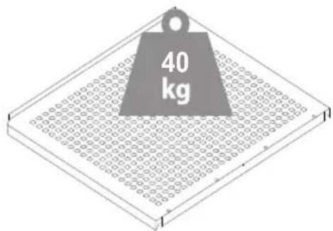
Abb.12
Temperatur +/-
Schrank on/off
Abb. 13
AVERTISSEMENT:
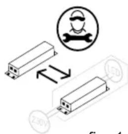
fig. 1
natural_image
Simple line drawing of a vertical panel with a circular button labeled 'P' (no text or symbols beyond the label)fig. 2
fig. 3
*Fixation de transport
natural_image
Technical line drawing of a mechanical component with a circular feature and mounting bracket (no text or symbols)fig. 4
natural_image
Simple black-and-white diagram of a horizontal line with two downward-pointing triangles (no text or symbols)natural_image
Technical line drawing of a mechanical assembly with a screw and base component (no text or symbols)fig. 11
natural_image
Line drawing of a hand inserting a plastic clip into a door panel (no text or symbols)fig. 10
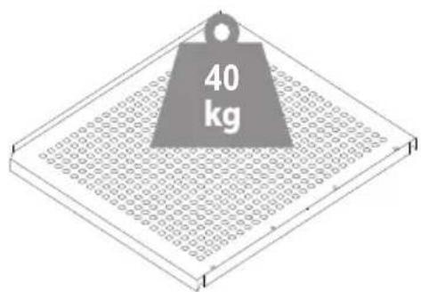
fig. 12
ATTENZIONE:
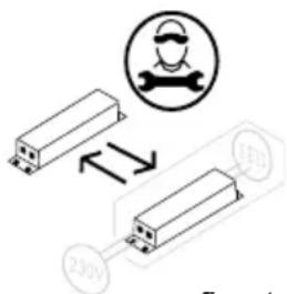
fig. 1
Dati tecnici
natural_image
Technical line drawing of a mechanical component with a circular feature and mounting bracket (no text or symbols)fig. 4
natural_image
Simple black geometric shape with two downward-pointing triangles on a horizontal line (no text or symbols)natural_image
Line drawing of a hand holding a plastic clip attached to a door (no text or symbols)fig.10
natural_image
Technical line drawing of a mechanical assembly with a bolt and bracket (no text or symbols)fig. 11
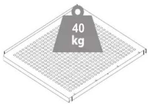
fig. 12
ADVARSEL:
flowchart
graph LR
    A["Sun"] --> B["Square Window"]
    style A fill:#fff,stroke:#000
    style B fill:#fff,stroke:#000
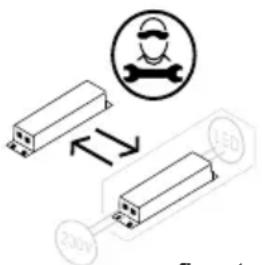
fig. 1
Tekniske data
natural_image
Line drawing of a mechanical component with a circular feature and a handle (no text or symbols)fig. 4
Installation
Placering
natural_image
Simple black geometric shape with two downward-pointing triangles on a horizontal line (no text or symbols)natural_image
Technical line drawing of a mechanical assembly with a threaded bolt and bracket (no text or symbols)fig. 11
" Et "Side by Side" kit kan bestilles. (fig 9)
natural_image
Line drawing of a hand inserting a plastic clip into a door (no text or symbols)fig. 10
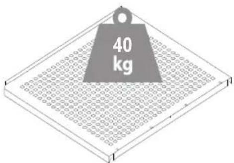
fig. 12
fig. 13
Elektronisk kontrol
WARNING:
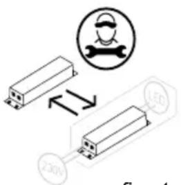
fig. 1
natural_image
Line drawing of a door handle with a circular button labeled 'D' (no text or symbols beyond the label)fig. 4
natural_image
Simple black geometric shape with two downward-pointing triangles on a horizontal line (no text or symbols)natural_image
Line drawing of a hand inserting a plastic clip into a door panel (no text or symbols)fig. 10
Konfiguration
natural_image
Technical line drawing of a mechanical assembly with a threaded component and base (no text or symbols)fig. 11

fig. 12
Drift och funktion
ADVARSEL:

fig. 1
natural_image
Technical line drawing of a mechanical component with a circular feature and a handle (no text or symbols)Fig. 4
natural_image
Simple black geometric shape with two downward-pointing triangles on a horizontal line (no text or symbols)natural_image
Line drawing of a hand holding a plastic clip attached to a wall, with no text or symbols present.Fig. 10
Sette opp
Det er viktig at apparatet er helt i vater. Du kan nivellere det ved å skru den justerbare foten foran på apparatet opp eller ned (fig. 11).
natural_image
Technical line drawing of a mechanical assembly with a threaded bolt and bracket (no text or symbols)Fig. 11
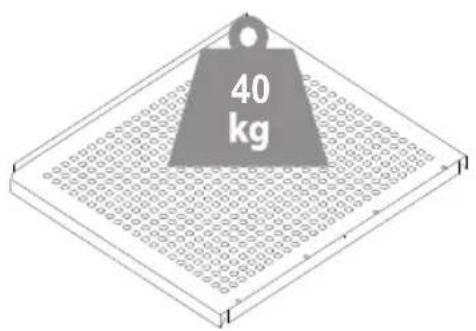
Fig. 12
Drift og funksjon
Lys av/på
Avising
Justere temperatur.
Hold knappen inn i 2 se- kunder.
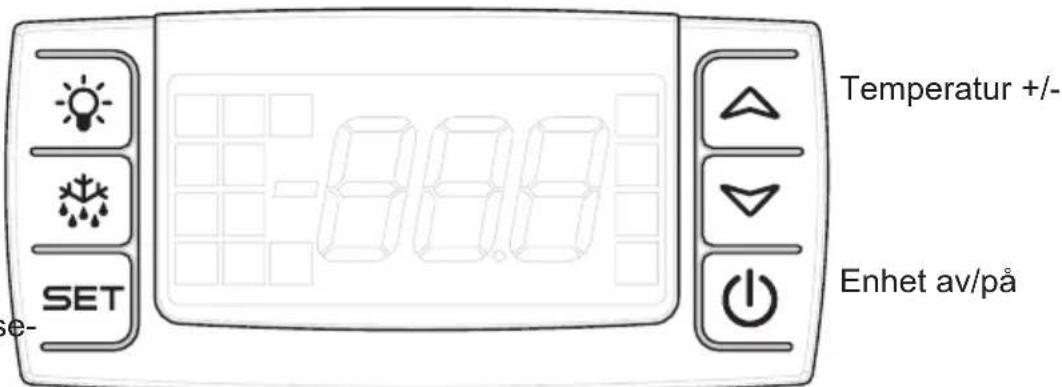
Fig. 13
Elektronisk betjening
natural_image
Warning symbol of a flame inside a triangle (no text or numbers)VAROITUS:
flowchart
graph LR
    A["Sun Icon"] --> B["Square Frame"]
    style A fill:#fff,stroke:#000
    style B fill:#fff,stroke:#000
Kuva 1
natural_image
Line drawing of a door handle with a circular button labeled 'D' (no text or symbols beyond the label)Kuva 4
natural_image
Simple black geometric shape with two downward-pointing triangles on a horizontal line (no text or symbols)natural_image
Line drawing of a hand inserting a plastic clip into a door panel (no text or symbols)Kuva 10
Käyttöönotto
natural_image
Technical line drawing of a mechanical assembly with a threaded bolt and bracket (no text or symbols)Kuva 11
Kuva 12
Käyttö ja toiminnot
DECLARATION OF CONFORMITY
Made in Denmark by A/S Vestfrost
Falkevej 12, 6705 Esbjerg ∅, Denmark and Sp. Møllevej 100, 6705 Esbjerg ∅, Denmark Telephone 45 79 14 25 25 Telephone 45 79 14 22 22
The undersigned declare that the product is in conformity with the relevant statutory requirements and the applicable parts of harmonized European standards:
Low Voltage Directive 2014/35/EU
EN 60335-1:2012+A11+A13+A1+A14+A2
EN 60335-2-24:2010+A1+A2+A11
EN 62233:2008
Electromagnetic Compatibility Directive 2014/30/EU
EN 61000-3-3: 2013
EN 61000-3-2: 2014
EN 55014-1: 2017+A11
EN 55014-2: 1997+A1+A2+AC
Ecodesign Directive 2009/125/EC
Eco design of household refrigerating appliances 2019/2019
Restriction of Hazardous Substances Directive (RoHS) 2011/65/EU
A/S VESTFROST
2021.10.19
Appliance Certification Manager
Jørgen Dyrholm
name
Esbjerg Denmark
VESTFROST
SOLUTIONS
A/S Vestfrost
Falkevej 12
DK-6705 Esbjerg ∅, Denmark
Tel: +45 79 14 22 22 · Fax: +45 79 14 23 55
Jorgen Dyrholm signature
Esbjerg Denmark
GB Reserving the right to alter specifications without prior notice.

- MFG 185 - Full Glas
- WARNING:
- Contents
- Electrical connection
- Information regarding voltage, current or power are given on the rating plate
- Get to know your bottle cooler
- Before use
- Installation
- Placement
- Ambient temperature
- Setting up
- Operation and function
- Electronic controls
- Manual defrosting
- Temperature display
- Temperature setting
- Beware
- Defrosting, cleaning and maintenance
- Automatic defrosting
- Cleaning
- Warranty, spare parts and service
- Warranty disclaimer
- Spare parts
- Disposal
- Warnung
- WARNUNG:
- Technische Daten
- Inbetriebnahme
- Aufstellort
- Aufstellen
- AVERTISSEMENT:
- ATTENZIONE:
- Dati tecnici
- ADVARSEL:
- Tekniske data
- Placering
- Elektronisk kontrol
- Konfiguration
- Drift och funktion
- Sette opp
- Drift og funksjon
- Elektronisk betjening
- VAROITUS:
- Käyttöönotto
- Käyttö ja toiminnot
- DECLARATION OF CONFORMITY
- Made in Denmark by A/S Vestfrost
- A/S VESTFROST
- VESTFROST
Brand : VESTFROST
Model : MFG 185
Category : Fridge