
DEU312 - Dehumidifier Bimar - Free user manual and instructions
Find the device manual for free DEU312 Bimar in PDF.
| Product type | Dehumidifier |
| Brand | Bimar |
| Model | DEU312 |
| Power supply | 230 V ~ 50 Hz (check the rating plate) |
| Minimum room area | 2 m² |
| Operating temperature | 5 °C to 32 °C |
| Water tank | Removable, with level indicator and automatic shut-off |
| Main functions | Automatic and continuous dehumidification (laundry drying), timer (1-24 h), high/low ventilation, internal drying, humidity display |
| Refrigerant gas type | R290 (flammable) |
| Gas quantity | Approximately 40 g |
| Protection rating | IP21 |
| Filter maintenance | Clean every 2 weeks with ambient water |
| Automatic full tank shut-off | Yes, with indicator light and audible signal |
| Continuous drainage | Possible via hose (internal diameter 9 mm, max length 1 m) |
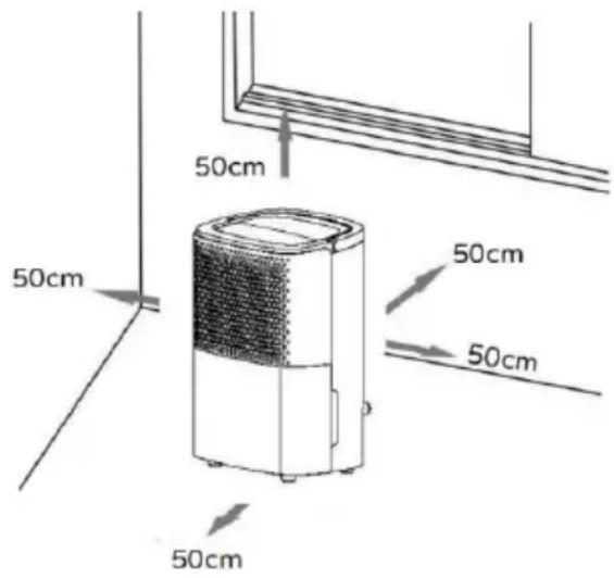
| Minimum distance around the appliance | 50 cm |
| Weight | Not specified |
| Dimensions | Not specified |
Frequently Asked Questions - DEU312 Bimar
User questions about DEU312 Bimar
0 question about this device. Answer the ones you know or ask your own.
Ask a new question about this device
Download the instructions for your Dehumidifier in PDF format for free! Find your manual DEU312 - Bimar and take your electronic device back in hand. On this page are published all the documents necessary for the use of your device. DEU312 by Bimar.
USER MANUAL DEU312 Bimar
natural_image
Diagram of a portable air purifier with ventilation slots and cooling unit (no text or labels)- Serbatoio
Thank you for buying our Bimar DEU312 dehumidifier.
Air contains a certain amount of water in the form of vapour. This vapour determines the degree of humidity in a particular environment. As the temperature goes up, the capacity of the air to hold water vapour increases. This is why as soon as the temperature in the house drops, the air releases the water vapour that is in it, which is then deposited as condensation on cold surfaces, such as windows, walls, etc. The dehumidifier gets rid of part of the humidity from the air and stops, for example, mould or mildew forming. According to experts, the ideal conditions for our health and for the home are between 40% and 60% relative humidity.

This symbol tells you to read these instructions carefully before using the appliance, and to inform any third parties if necessary. Keep the instruction booklet for further reference throughout the lifetime of the appliance. If when reading these instructions you find any parts difficult to understand or have any doubts, contact the manufacturer at the address provided on the back page before using the product.

Caution: this symbol indicates that there may be additional information in the manual attached. It tells you there is further information in the manual.

This symbol indicates that the user must refer to the installation manual when handling the appliance.

This symbol highlights instructions and precautions for safe use.
IPX1
This symbol indicates that the sealing class is IP21
The appliance is protected against solid objects ≥ 12,5mm in diameter entering it and the vertical drop of water droplets.
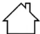
This symbol indicates:
Only use the appliance indoors.
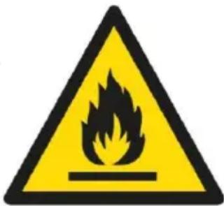
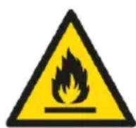
This symbol indicates:
Caution: Fire hazard.
The appliance uses a flammable refrigerant. If the refrigerant escapes and is exposed to an external source of ignition, there is a risk of fire.
GENERAL WARNINGS
- This appliance is intended for domestic use only (therefore not suitable for professional use), to dehumidify, i.e. reduce percentage of relative humidity in indoor environments, in manner reported in this manual. Do not use the appliance outdoors, or in particularly dusty environments, or in the presence of extremely volatile materials which could clog t filter or damage the motor.
- Examples of household appliances are appliances for typical household functions, those used in the home, or those who may be used for typical household functions even by untrained persons:
- in shops, offices and other similar workplaces;
- on farms and in similar locations;
- by the customers of hotels, motels and other residential environments;
- in bed and breakfast establishments.
- The appliance has been designed to work at temperatures between 5^ and 32^ .
- Only use the dehumidifier if all the components are correct inserted.
- Always use the dehumidifier in an upright position only; does sit or stand on the unit.
- Warning: when using electrical appliances, always comply the basic safety precautions to avoid the risks of fire, electric shock and physical injury. Greater care and precautions must be taken when using electrical appliances that are equipped with a water tank - if the water overflows or if the cord or the plug should get wet, first disconnect the device from the
power socket by turning it off at the switch on the electrical panel and only unplug from the socket afterwards. Dry bot the plug and the mains cable carefully before plugging into the power socket again. If in doubt, contact a qualified professional.
- This appliance can be used by children aged from 8 years above and persons with reduced physical, sensory or mental capabilities or lack of experience or the necessary knowledge providing they are supervised or have been instructed on to safe use of the appliance and understand the hazards involved. Children should not play with the appliance. Clean and maintenance intended to be carried out by the user should not be done by children unless they are supervised.
- Take suitable precautions to prevent children from playing with the appliance. The appliance and all its accessories should be kept out of the reach of children.
- Do not obstruct the air inlet or air outlet grille.
- Do not insert fingers or objects into the ducts of the air inlet and outlet grilles.
- Do not touch the appliance or the plug with wet hands or f
- Avoid exposing parts of the body to the outflowing air of t appliance, to avoid harming one’s health.
- Unplug the appliance from the socket when not in use.
- Do not move the appliance while in operation.
- Do not pull on the power cable or the appliance itself to re the plug from the power socket.
-
Do not move the appliance by pulling the cable.
-
Always disconnect the appliance from the power socket be assembling, dismantling, emptying the tank, and before cleaning the filter and the appliance.
- If the power cable is damaged, it must be replaced by the manufacturer or its technical support service, or by a person with similar qualifications, to prevent all risks.
- This appliance is not intended for operation by means of a external timer or with a separate remote control system, to avoid the risk of fire if the appliance is covered or not corre positioned.
- Never leave the device exposed to the elements (sun, rain,
- To guard against all risk of electric shock, do not immerse plug, the mains cable or the appliance in water or any other liquid.
- Do not drink or use the water that collects in the tank.
- Any other use constitutes misuse and is hazardous. The manufacturer cannot be held liable for any damage arising from misuse or incorrect or irresponsible use, and/or fire repairs carried out by unqualified persons.
This product contains fluorinated greenhouse g This product is hermetically sealed. R290 GWP refrigerant: 3.
Additional warning for appliances with refrigera R290 (refer to the data plate for the type of gas Caution: Fire hazard.
Please read these instructions carefully before the appliance. R290 is a refrigerant gas that cor to EU environmental directives.
This appliance contains approximately 40g of R refrigerant gas.
The appliance must be installed, used and store place with a surface area greater than 2 m^2 .
Do not pierce any part of the refrigerant circuit.
1.WARNING FOR R290 REFRIGERANT GAS
1.1 The appliance contains R290 gas (flammability classification A3).
The appliance shall be stored in a room Without continuously operating ignition sources (for example open flames, an operating gas appliance or an operating electricheate):
Be aware that the refrigerants may not contain an odour. R290 is a refrigerant gas in compliance with the European directives on environment. do not pierce any part of the refrigerant circuit.
Do not use means to accelerate the defrosting process or to clean, other than those recommended by the manufacturer. Do not use tools different from those recommended by the manufacturer
when defrosting and cleaning the appliance.
If the appliance is installed, used or stored in a non-ventilated air room must be designed to prevent the accumulation of refrigerant leaks with the consequent fire or explosion hazard due to the refrigerant combustion caused by electrical heating stoves or others sources of ignition.
Compliance with national gas regulations shall be observed. Keep ventilation openings clear of obstruction.
The appliance shall be stored so as to prevent mechanical damage from occurring.
Any person who is involved with working on or breaking into refrigerant circuit should hold a current valid certificate from
industry-accredited assessment authority, which authorises their competence to handfeigerants safely in accordance with an industry recognised assessment specification.
Servicing shall only be performed as recommended by the equipment manufacturer. Maintenance and repair requiring the assistance of other skilled personnel shall be carried out under the supervision of the person competent in the use of flammable refrigerants.
Transport of equipment containing flammable refrigerants.
See transport regulations.
Marking of equipment using signs.
See loca·tegulations.
Disposal of equipment using flammable refrigerant.
See national regulations.
Storage of equipment/appliances.
The storage of equipment should be in accordance with the manufacturer's instructions.
Storage of packed (unsold) equipment.
Storage package protection should be constructed such that mechanical damage the equipment inside the package will not cause a leak of the refrigerant charge maximum number of pieces of equipment permitted to be stored together will be determined by local regulations.
Information on servicing
Checks to the area. Prior to beginning work on systems containing flammable refrigerants, safety checks are necessary to ensure that the risk of ignition is minimised.
For repair to the refrigerating system, the following precautions shall be complied with prior to conducting work on the system
Work procedure. Work shall be undertaken under a control procedure so as to minimise the risk of a flammable gas or vapour being present while the work is being performed.
General work area. All maintenance staff and others working the local area shall be instructed
on the nature of work being carried out. Work in confined spaces shall be avoided. The area around the workspace shall be sectioned off. Ensure that the conditions within the area I been made safe by control of
flammable material.
1.1.5 Checking for presence of refrigerant areas shall be checked with an appropriate refrigerator and detectoprior to and during work, to ensure the technician is aware of potentially flammable atmospheres. ensure that the leak detection equipment being used is suitable for use with flammable refrigerants, i.e. non-sparking, adequately sealed or intrinsic safe.
1.1.6 Presence of fire extinguisher. if any hot work is to be conducted on the refrigeration equipment associated parts, appropriate fire extinguishing equipment shall be available hand.
Have a dry powder or CO2 fire extinguisher adjacent to the charging area.
1.1.7 No ignition sources. No person carrying out work in relation to a refrigeration system which involves exposing an pipe work that contains or has contained flammable refrigerant shall use any sources of ignition in such a manner that it may lead to the risk of fire or explosion.
all possible ignition sources, including cigarette smoking, shall be kept sufficiently far away from the site of installation,
repairing, removing and disposal, during which flammable refrigerant can possibly be released to the surrounding space. Prior to work taking place, the area around the equipment is be surveyed to make sure that there are no flammable hazard or ignition risks. No Smoking signs shall be displayed.
1.1.8 Ventilated area. Ensure that the area is in the open or it is adequately ventilated before breaking into the system of conducting any hot work.
a degree of ventilation shall continue during the period that work is carried out the ventilation should safely dispersen any released refrigerant and preferably expel it externally into the atmosphere.
1.1.9 Checks to the refrigeration equipment. Where electric components are being changed, they shall be fit for the purpose and to the correct specification. At all times the manufacturer's maintenance and service guidelines shall be followed. If in doubt consult the manufacturer's technical department for assistance.
The following checks shall be applied to installations using flammable refrigerant: The charge size is in accordance with the room size within which the refrigerant contains an installed ventilation machinery and outlets are operating adequately and are not obstructed; if an indirect refrigerator circuit is being used, the secondary circuit shall be checked the presence of refrigerant; marking to the equipment continues to be visible and legibleings and sign that are illegible shall be corrected refrigeration pipe or components are installed in a position where they are unlikely to be exposed any substance which may corrode refrigerant containing components, unless these components are constructed of
materials which are inherently resistant to being corroded or suitably protected against being so corroded.
Checks to electrical device and maintenance electrical components shall include initial safety checks and component inspection procedures. if a fault exists that could compromise safety, then no electrical supply shall be connected to the client until it is satisfactorily dealt with. if the fault cannot be corre immediately but it is necessary to continue operation, an adequate temporary solution shall be held before reported to the owner of the equipment all parties are advised. Initial safety checks shall include that capacitor are discharged: this shall be done in a safe manner to avoid possibility of sparking; that there are live electrical components and wiring are exposed while charging, recovering using the system that there is continuity of earthbonding.
Repairs to sealed components during repairs to sealed components, all electrical supplies shall be disconnected from the equipment being worked upon prior to any removal of sealed covers, etc. if it is absolutely necessary to have an electrical supply to equipment during servicing, then a permanently operating form of leak detection shall be located at the most critical point to warn of a potentially hazardous situation. Particular attention shall be paid to the following 10% ensure that by working on electrical components, the casing not altered in such a way that the level of protection is affected. This shall included damage to cables, excessive number of connections, terminals not made to original specification, damage to seals, incorrect fitting of glands, etc. Ensure that apparatus is mounted securely. Ensure that seals or sealing materials have not degraded such that they serve the
purpose of preventing the ingress of flammable atmospheres. replacementparts shall be in accordancewith the manufacturerspecifications.
Repair to intrinsically safe components not apply any permanent inductive or capacitance loads to the circuit with ensuring that this will not exceed the permissible voltage and current permitted for the equipment in use. Intrinsically safe components are the only types that can be worked on while in the presence of a flammable atmosphere apparatus shall be at the correct rating Replace components only with parts specified by the manufacturer. Other parts may result in the ignition of refrigerant in the atmosphere from a leak.
CablingCheck that cabling will not be subject to wear, corrosion, excessive pressure, vibration, sharp edges or any other adverse environmental effects. The check shall also ta into account the effects of aging or continual vibration from sources such as compressors or fans.
Detection of flammable refrigerants. Under no circumstance shall potential sources of ignition be used in the searching for detection of refrigerant leaks. A halide torch (or any other detector using a naked flame) shall not be used.
Leak detection methods are following leak detection methods are deemed acceptable for systems containing flammable refrigerants. Electronic leak detectors shall be used to detect flammable refrigerants, but the sensitivity may not be adequate, or may need re-calibration. (detection equipment shall be calibrated in a refrigerant-free area). Ensure that the detector is not a potential source of ignition and is suitable for the refrigerant use. Detection equipment shall be set at a percentage of the if of the refrigerator and shall be calibrated
to the refrigerant employed and the appropriate percentage gas (25 % maximum) is confirmed. Leak detection fluids are suitable for use with most refrigerants but the use of detergent containing chlorine shall be avoided as the chlorine may reach with the refrigerant and corrode the copper pipe-work. If a light is suspected, all naked flames shall be removed/ extinguishing a leakage of refrigerant is found which requires brazing, all of the refrigerant shall be recovered from the system, or isolated (by means of shut off valves) in a part of the system remote from the leak oxygen free nitrogen (ofn) shall then be purged through the system before and during the brazing process.
Removal and evavuation. When breaking into the refrigeran circuit to make repairs or for any other purpose conventional procedures shall be used. However, it is important that best practice is followed since flammability is a consideration. T following procedure shall be adhered to:
Remove refrigerant;
Purge the circuit with inert gas;
Evacuate;
Purge again with inert gas;
Open the circuit by cutting or brazing.
The refrigerant charges shall be recovered into the correct recovery cylinders.
The system shall be flushed with OFN to render the unit safe. This process may need to be repeated severatimes. Compressed air or oxygen shall not be used for this task.
Flushing shall be achieved by breaking the vacuum in the system with ofn and continuing to fill until the working pressure is achieved, then venting to atmosphere, and finally pulling dc
to a vacuum hit process shall be repeated until no refrigerant within the system. When the final OFN charge is used, the system shall be vented down to atmospheric pressure to enable work to take place. This operation is absolutely vital if Brazil operations on the pipe-work are to take place. Ensure that the outlet for the vacuum pump is not close to any ignition source and there is ventilation available.
Charging Procedures addition to conventional charging procedures, the following requirements shall be followed. Ensure that contamination of different refrigerants does not occur when using charging equipment. Hoses or lines shall be as short as possible to minimise the amount of refrigerant contained in them. Cylinders shall be kept upright. Ensure that the refrigeration system is earthed prior to charging the system with refrigerant and the system when charging is complete (if not already). Extreme care shall be taken not to overfill the refrigeration system. Prior to recharging the system it shall be pressure tested with. The system shall be leak tested on completion of charging but prior to commissioning. a follow up leak test shall be carried out prior to leaving the site.
Decommissioning Before carrying out this procedure, it is essential that the technician is completely familiar with the equipment and all its detail. It is recommended good practice that all refrigerants are recovered safely. Prior to the task be carried out, an oil and refrigerant sample shall be taken in ca analysis is required prior to re-use of reclaimed refrigerant. It is essential that electrical power is available before the task is commenced.
-Become familiar with the equipment and its operation. Isola system electrically. Before attempting the procedure ensure that:
-Mechanical handling equipment is available, if required, for handling refrigerant cylinders;
All personal protective equipment is available and being used correctly.
-The recovery process is supervised at all times by a competent person;
-Recovery equipment and cylinders conform to the appropriate standards.
-Pump down refrigerant system, if possible.
- If a vacuum is not possible, make a manifold so that refrigeration can be removed from various parts of the system.
-Make sure that cylinder is situated on the scales before recovery takes place.
-Start the recovery machine and operate in accordance with manufacturer's instructions.
-Do not overfill cylinders. (No more than 80 % volume liquid charge).
-Do not exceed the maximum working pressure of the cylinder even temporarily.
-When the cylinders have been filled correctly and the process completed, make sure that the cylinders and the equipment removed from site promptly and all isolation valves on the equipment are closed off.
-Recoveredrefrigeranshallnot be chargedinto another refrigeration system unless it has been cleaned and checked.
1.1.19 Labelling. Equipment shall be labelled stating that it been de-commissioned and emptied of refrigerant labelTh
shalbe dated and signed. Ensure that there are labels on the equipment stating the equipment contains flammable refrigerant.
1.1.20 Recovery. When removing refrigerant from a system, either for servicing or decommissioning, it is recommended good practice that all refrigerants are removed safely.
When transferring refrigerant into cylinders, ensure that only appropriate refrigerant recovery cylinders are employed.
Ensure that the correct number of cylinders for holding the system charge is available. All cylinders to be used are designated for the recovered refrigeral labained for that refrigerant (i.e. special cylinders for the recovery of refrigerant).
Cylinders shall be complete with pressure relief valve and associated shut-offs in good working order. Empty recovery cylinders are evacuated and, if possible, cooled be recovery occurs. Recovery equipment shall be in good working order with a set of instructions concerning the equipment that is at hand and shall be suitable for the recovery of flammable refrigerants. In addition, a set of calibrated weighing scales be available and in good working order. Hoses shall be complete with leak-free disconnect couplings and in good condition. Before using the recovery machine, check that it is in satisfactory working order, has been properly maintained and that any associated electrical component sealed to prevent ignition in the event of a refrigerant release. Consult manufacturer if in double recovered refrigerant shall be
returned to the refrigerator supply in the correct recovery cylinder, and therelevant Waste transfer note arranged do not mix refrigerants in recovery units and especially not in cylinders. compressors or compressor oils are to be removed, ensure t
they have been evacuated to an acceptable level to make certain that flammable refrigerant does not remain within the lubricant. He evacuation process shall be carried out prior to returning the compressor to the suppliers. Only electric heating to the compressor body shall be employed to accelerate this process.
When oil is drained from a system, it shall be carried out saf
INSTALLATION
- After removing the packaging, check that the appliance is intact; if in doubt, do not use it and contact a qualified professional. Packaging components (plastic bags, polystyrene, metal staples, etc.) must not be left within reach of children or persons with diminished responsibility, since they are potentially hazardous; they must be disposed of in accordance with the current law.
- Before connecting the appliance, check that the data plate (voltage, etc.) are the same as those of your mains electricity supply. This appliance must be connected to a socket that has an effective earthing device (the manufacturer declines any liability that may arise from failure to comply with this rule). Check that no other appliances with a high energy consumption are connected to the power supply, to avoid overloading and the risk of fire. In general, the use of adapters, multiple sockets and/or extension leads is not recommended. If their use is unavoidable, they must comply with current safety regulations and their current capacity (amps) must be no lower than the maximum current draw of the appliance.
- The appliance must be installed and/or placed in a location with a surface area of at least 2m^2 .
- Do not install the dehumidifier in environments where there are flammable products (spray cans or canisters containing gas, liquids or solids), or in dusty environments.
- Place the appliance: away from sources of heat, keep away from fabrics (curtains, hanging laundry, etc.) or anything else that might come into contact and/or obstruct the inlet and outlet grilles; keep away from bathtubs, sinks or similar, to avoid the appliance being splashed with water, or falling into these.
- Ensure there is a free space around the appliance of at least 50 cm.
- The appliance must be placed on a stable surface that is wide (do not place on a shelf), not on an incline (the water may overflow and escape), or in a place where it might be knocked.
• The appliance must not be placed just below a power socket.
- The power socket must be easily accessible so that the plug can be removed easily in an emergency.
- Make sure that the mains cable is correctly positioned and is not in contact with hot parts or sharp edges, or wound around the appliance or twisted and does not become entangled, to prevent the appliance from falling.
- If tank drainage is in use, check that the continuous drainage spout is tightly sealed with its rubber cap each time the appliance is turned on.
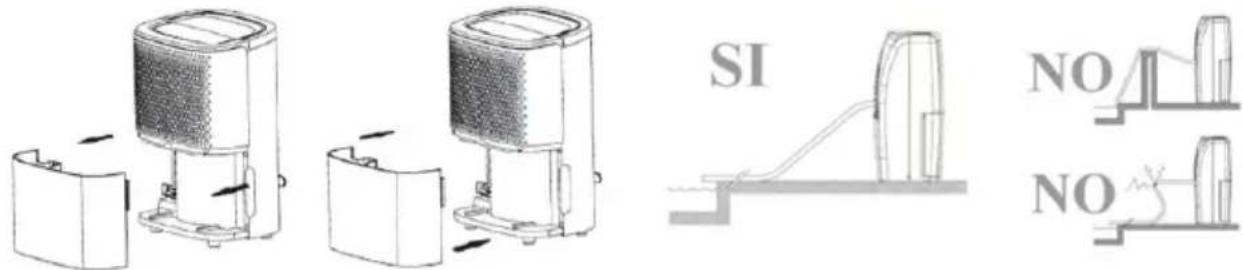
- If continuous drainage is on, make sure that the drainage tube is properly connected to the spout, that the opposite end is lower than the spout, and that the incline is even, so that the water flows internally without any obstructions.
- Caution: do not cover the appliance to avoid overheating.
- The appliance does not require installation, i.e. preparation of electrical attachments/water connection /fixtures or other installations, before use.
- Before each use, check that the appliance is in good condition and ensure that the power cable is not damaged.
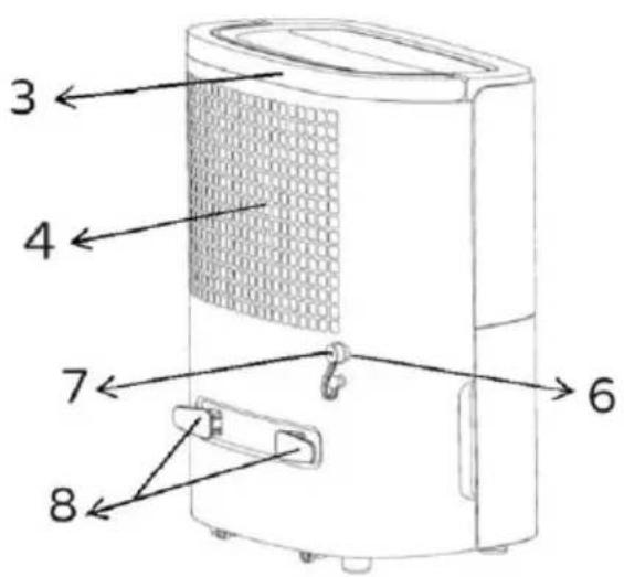
DESCRIPTION
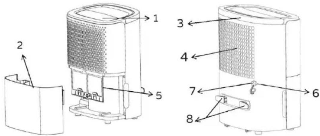
The appliance is equipped with the following parts and elements for control and regulation: (1), Removable tank (2), Handle for transportation (3), Air outlet grille (4), Filter (5), Continuous drainage spout (6) and rubber cap (7), Cord winding fixtures (8), Continuous drainage tube (only supplied with certain models).
Each component has the following functions:
Control Panel
Depicted below: it has push buttons that activate the functions, LED lights and display to view functions and data.
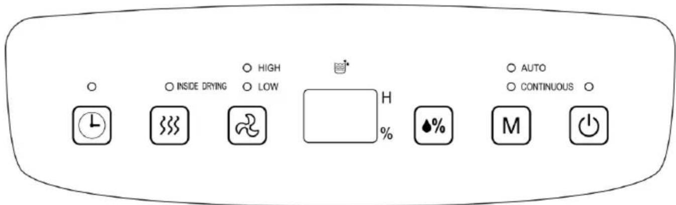
 | On/Off Button | Turns on the appliance and puts on standby. The fan starts up after a few moments and then the compressor starts up (if necessary). |
 | Mode Button | Selects Automatic or Continuous dehumidifying (dry laundry function): only works when the appliance is switched on. When the the mode is selected, the corresponding LED light flashes. |
 | Humidity Button | Select the relative humidity button (HR%). The function only works when on “Auto” mode. Press the button to select 30 to 80 HR% (the pre-set value is 50%): each time it is pressed, it increases by 5%. The value can be viewed on the display, which after a few moments shows the current value. |
 | Fan Button | Select the fan: “High” or “Low”. |
 | Inside Drying Button | This activates internal drying and the drying of the frost that can form on the evaporation coil. The display shows “CL” and the “inside drying” LED light flashes. The process lasts for approximately one hour, and no other function can be used. To stop the drying, press the button again or press “On”. |
 | Timer Button | This times the appliance operation or start-up: each time the button is pressed, the time increases by one hour, up to a maximum of 24 hours. If pressed again, the time is cancelled. To time the operation, turn on the appliance, set the humidity level, the fan and the mode, then set the timer to the desired time (1-24h): the appliance will turn off after the time set on the timer is finished.To delay start-up, press the button until the required time is reached (1-24h), then set the mode, fan and humidity level. The appliance will start up after the time set on the timer. |
 | Display | View time (hours) and humidity (%) |
 | Tank gauge | Indicates that the tank is full. |
Drainage.
The water can be drained:
- Via the tank (2). The water condensation is collected in the tank and when it is full, the internal float puts the appliance on standby, the gauge on the panel lights up and a signal will sound. Remove the tank without spilling any water, empty it and dry it. Check that the float is free to move and replace it correctly. The transparent slot on the front of the tank shows the water level.
- Continuous
The continuous drainage spout (6), on the back of the appliance has a rubber cap (7): remove the cap and attach the rubber tube with 9mm internal diameter and 1m max. length (comes supplied with some models). Make sure the connection is leak-proof.
Check that the drain is at a lower height than the spout and that the whole tube is sloping evenly and that it is lower than the spout.
Do not remove the water tank from its place.
If continuous drainage is not in use, remove the drainage tube and close the spout with the rubber cap.
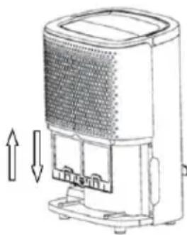
Filter
The air inlet grille has a filter (5) which traps dust: it is placed internally and to access it, it is necessary to remove the tank. It is accessible from the bottom - slide downwards gripping the central clasp with two fingers. See the paragraph below for filter maintenance. Replace so that the two clips are down and facing frontwards.
Follow the indications (arrows and "FRONT") printed on the edge.
Handle
There is a foldable handle on the top (3), for transportation.
Cord Winder
There are fixtures on the back (8) to wind the mains cable around.
USE
Before each use, make sure that:
-the appliance is in good condition
-that the mains cable is not damaged
-that the tank is empty, and fully in place.
-that the water drainage spout is properly closed with the cap whenever the tank is used, or the drainage tube is inserted properly and in place whenever continuous drainage is used.
-
Connect the plug to the power socket.
-
Turn on the appliance by pressing ⏻ and activate the desired function, following the instructions above.
- When removing the tank, the dehumidifier will stop the compressor and after approximately 3 minutes the fan will stop: the appliance is now on standby. Once it is back in place, the appliance will automatically start in a few moments.
- To deactivate the appliance, press the ⏻ button. Go to standby and to switch it off completely, remove the plug from the power socket.
- Except when ventilating the environment, keep windows and doors closed, to maximise the effects of the dehumidifier.
During long periods of inactivity, remove the plug from the electric socket.
CLEANING AND MAINTENANCE
Warning: disconnect the plug from the power socket before routine cleaning. Keep the appliance in an upright position during cleaning.
- Filter
It is advisable to clean the filter periodically (approximately every two weeks max. or more often if the appliance is used daily).
Remove the tank, slide the filter downwards and remove it. When cleaning the filter, only use lukewarm water. Do not use hot water, detergents, solvents, abrasives or similar. Dry thoroughly (do not use hot air) and then replace it correctly into position.
natural_image
Diagram of a portable air purifier with ventilation grilles and cooling unit (no text or labels)- Tank
It is advisable to empty it after every use and wash it periodically to avoid the formation of bacteria or unpleasant smells. To clean the tank, use lukewarm water with a regular detergent for crockery (do not use abrasives, solvents or similar), wash it and replace it into position.
- Main Unit
Wash only with a soft cloth dampened with water.
- When not in use for long periods, empty the water from the tank, wind the cable around the cord winder, store in an upright position, away from dust and humidity, and respecting the precautions set out in the warnings section.
- If you decide not to use the appliance any more, it must be rendered unusable by cutting off the power-supply cord (first making sure that the plug has been removed from the power socket), and any parts which are hazardous if used as children's playthings must be rendered harmless.
- Gas R290
Please be reminded to follow the instructions in the warnings section.
Information for correct disposal of the product under the European Directive directive 2011/65/EU.
At the end of its lifetime, the product must not be disposed of with ordinary urban waste.
It can be consigned to the special waste recycling centres provided by local government, or by the retailers who provide this service.
Proper disposal of a household appliance prevents possible detrimental effects on the environment or health arising from its incorrect disposal and allows the recovery of its constituent materials, generating major savings of energy and resources. The product bears the crossed-out symbol of a wheeled rubbish bin to indicate that it must be disposed of separately. Illegal dumping of the product by the user will be subject to prosecution under the relevant law.

TROUBLESHOOTING
| Problem | Possible reason | Solution |
| If the fan and compressor do not work. | The appliance is not on. | Turn on the appliance. |
| The electrical socket is defective. | Seek advice from a qualified professional. | |
| The plug is not connected to the socket. | Connect the plug to the power socket. | |
| The tank full gauge is on. | Empty the water tank. | |
| The water tank is not properly inserted, tank full light gauge is on. | Reposition the tank. | |
| The appliance does not dehumidify or does not dehumidify adequately. | The air filter is clogged. | Clean the filter as described in the section, “Cleaning and Maintenance”. |
| The windows and doors of the room are open. | Close the windows and doors of the room. | |
| The room temperature is too low. | Automatic defrosting is in operation; the appliance will start dehumidifying again once it stops. | |
| The time is not long enough to extract the humidity. | Increase the time. | |
| The air inlet or outlet grille is covered or blocked. | Make sure that the grilles are free. | |
| The dehumidifier is excessively noisy. | The dehumidifier is not correctly positioned or is not tilted and/or is unstable. | Position the dehumidifier on a flat stable surface. |
| The air filter is clogged. | Clean the filter as described in the section, “Cleaning and Maintenance”. |
Ce symbole indique:
natural_image
Line drawing of a portable air conditioner unit with ventilation grilles and cooling fins (no text or symbols)- Réservoir
natural_image
Diagram of a portable air purifier with airflow arrows indicating movement (no text or symbols)Este símbolo indica:
natural_image
Diagram of a portable air purifier with airflow arrows indicating movement (no text or symbols)- Depósito

Via G.Amendola, 16/18 25019 Sirmione (BS) – ITALY www.bimaritaly.it
Servizio clienti:

info@bimaritaly.it
DEU312_I.B._190404
- - Serbatoio
- IPX1
- GENERAL WARNINGS
- 1.WARNING FOR R290 REFRIGERANT GAS
- Information on servicing
- INSTALLATION
- DESCRIPTION
- Control Panel
- Drainage.
- - Continuous
- Filter
- Handle
- Cord Winder
- USE
- CLEANING AND MAINTENANCE
- - Filter
- - Tank
- - Main Unit
- - Gas R290
- Ce symbole indique:
- - Réservoir
- Este símbolo indica:
Brand : Bimar
Model : DEU312
Category : Dehumidifier