
RRE 810 - Electric heater Orbegozo - Free user manual and instructions
Find the device manual for free RRE 810 Orbegozo in PDF.
| Brand | Orbegozo |
| Model | RRE 810 |
| Product type | Electric radiator |
| Power | 800 W |
| Power supply | 220-240 V ~ 50 Hz |
| Operating modes | Comfort, Economy, Weekly programming, Frost protection |
| Thermostat | Electronic with weekly programmer |
| Remote control | Yes |
| Child safety (lock) | Yes (via remote control) |
| Open window detection | Yes |
| Temperature compensation | Yes, adjustable |
| Installation | Floor or wall |
| Frost protection | Yes (minimum temperature 7 °C) |
| Cleaning | Dust regularly with a soft cloth; do not use abrasive products |
| Warranty | Compliant with current legislation (2 years) |
Frequently Asked Questions - RRE 810 Orbegozo
User questions about RRE 810 Orbegozo
0 question about this device. Answer the ones you know or ask your own.
Ask a new question about this device
Download the instructions for your Electric heater in PDF format for free! Find your manual RRE 810 - Orbegozo and take your electronic device back in hand. On this page are published all the documents necessary for the use of your device. RRE 810 by Orbegozo.
USER MANUAL RRE 810 Orbegozo
natural_image
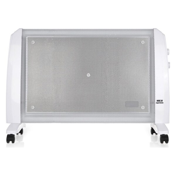
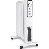
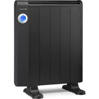
Four white electric heater units with blue indicator lights, arranged in a row (no text or symbols visible)RRE 510 A 810 A 1010 A 1310A 1510 A 1810 A
Read this manual carefully before running this appliance and save it for reference in order to obtain the best results and ensure safe use.
Fig. 4
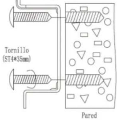
Fig. 5
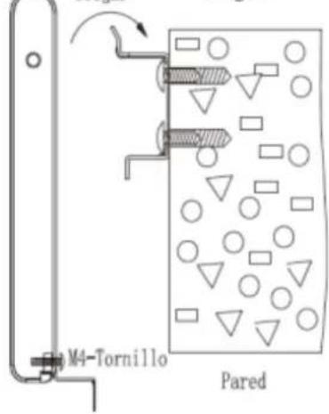
Fig. 6
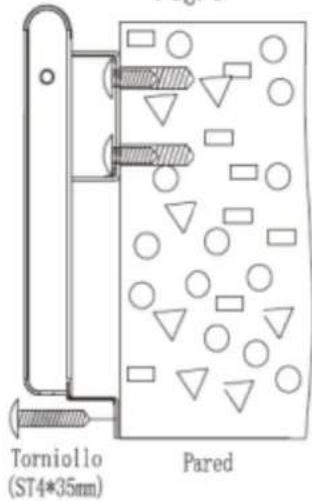
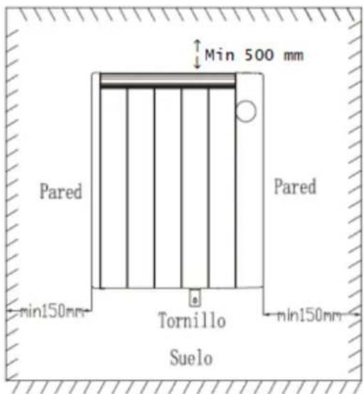
Fig.13
Cambiar modo:
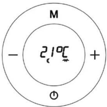
Fig.15
CÓMO PROGRAMAR SU CALEFACTOR:
Fig.16
Fig.21
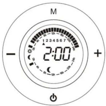
Fig.22
We congratulate you for having chosen our product.
Please read the following information carefully before using the appliance for the first time for your own safety and to ensure correct use.
Read the Safety information's and safe positioning also carefully before using of the heater about to avoid any risk of fire or lives.
SAFETY INSTRUCTIONS
Read the operating instructions carefully before putting the appliance into operation and keep the instructions including the warranty, the receipt and, if possible, the box with the internal packing. If you give this device to other people, please also pass on the operating instructions.
GENERAL SAFETY INSTRUCTIONS:
- This appliance can be used by children aged from 8 years and above and persons with reduced physical, sensory or mental capabilities or lack of experience and knowledge if they have been given supervision or instruction concerning use of the appliance in a safe way and understand the hazards involved. Children must never play with the appliance. Cleaning and user
maintenance must never be carried out by children without supervision.
- Children should be supervised to ensure that they do not play with the appliance.
- WARNING: In order to ensure your children's safety, please keep all packaging (plastic bags, boxes, polystyrene etc.) out of their reach.
- If the supply cord is damaged it must be repaired by the Authorized Service Agent in order to avoid hazards.
- Never pull on the cord when unplugging.
- Do not use the unit with a damaged cord or plug, or if it is not working properly.
- Do not handle the appliance with wet hands.
- Never immerse the appliance in water or any other liquid.
- Make sure the appliance has been unplugged before cleaning.
- This appliance must be installed following the national regulations for electrical installations.
- This appliance is for household use only.
- In case that you need a copy of the instruction manual, you can find it in www.orbegozo.com
- WARNING: In case of misuse, there is a risk of possible injury.
IMPORTANT SAFETY INSTRUCTIONS:
- The meaning of figure ☑ in marking is “DO NOT COVER”. WARNING: In order to avoid overheating, do not cover the heater.
- Children of less than 3 years should be kept away unless continuously supervised.
- Children aged from 3 years and less than 8 years shall only switch on/off the appliance provided that it has been placed or installed in its intended normal operating position and they have been given supervision or instruction concerning use of the appliance in a safe way and understand the hazards involved. Children aged from 3 years and less than 8 years shall not plug in, regulate and clean the appliance or perform user maintenance.
- CAUTION: Some parts of this product can become very hot and cause burns. Particular attention has to be given where children and vulnerable people are present.
- The device should not be placed immediately below a socket base.
- Do not place a heater in use near curtains, furniture, wood panelling or combustible material which can deteriorate with heat.
- Do not use this heater in the immediate vicinity of a bath, shower or pool.
- Do not use this heater with a programmer, timer or any other device that switches the heater on automatically, since a fire risk exists if the heater is covered or positioned incorrectly.
- Do not use the appliance in flammable atmospheres (e.g. in the vicinity of combustible gases or sprays cans)! Explosion and fire hazard!
- Do not use the heater in rooms with explosive gas (e.g. petrol) or while using inflammable glue or solvent (e.g. when gluing or varnishing parquet floors, PVC etc.) Do not allow aerosols, inflammable substances or materials sensitive to heat to be in the flow of hot air.
- Do not use the heater in areas or rooms which are a risk of fire, such as garages, stables, wooden shed etc.
- The unit must be mounted such that the control elements cannot be touched by persons who are in bath, shower, or any other water-filled receptacle.
• Always unplugged the heater after use. - Important! Do not insert any foreign objects into the appliance openings! Risk of injury (electric shock) and damage to the appliance!
-
Keep the mains cord at a safe distance from the air inlet and outlet grilles.
-
Do not use this heater if it has been dropped.
- Do not use if there are visible signs of damage to the heater.
- Use this heating appliance on a horizontal and stable surface, or if possible fix it to a wall.
- WARNING: Do not use this heater in rooms that are occupied by persons who cannot leave the room by themselves, unless permanent surveillance is provided.
- WARNING: To reduce the risk of fire, keep textiles, curtains, or other flammable material at least 1m away from the air outlet.
INSTALLING INSTRUCTIONS
This heater can be used freestanding or wall-mounted.
Free-standing:
- When used in freestanding position, it must be standing in a vertical position. Do not place the heater on instable surfaces, such as bed, carpets etc. and do not use the heater on uneven position, where the heater can tip-over-otherwise there is a risk of fire.
- Allow ample space around the heater. A safe area to be left free is 15 cm at the sides, and 20 cm at the front
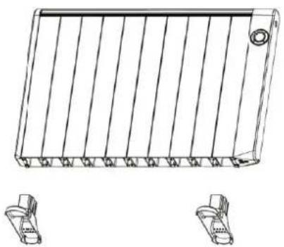
How to install the feet:
Insert the edges of the bottom of the radiator into the feet support as show in (see below figure 1, fig.1.1 and form) as below. You will hear a click to indicate that the installation was a success.
ATTENTION: When installing the appliance on its support feet, place it on a surface that supports high temperatures.
natural_image
Technical line drawing of a rectangular electronic component with vertical fins and mounting holes, shown with two separate connectors below (no text or symbols)Fig. 1 fig.1.1
natural_image
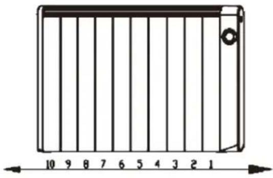
Diagram of a rectangular device with vertical bars and a scale bar, no text or symbols present| Model | Feet Position | |
| First feet | Second feet | |
| RRE 510 A | 1 | 3 |
| RRE 810 A | 1 | 5 |
| RRE 1010 A | 1 | 6 |
| RRE 1310 A | 1 | 7 |
| RRE 1510 A | 1 | 8 |
| RRE 1810 A | 1 | 10 |
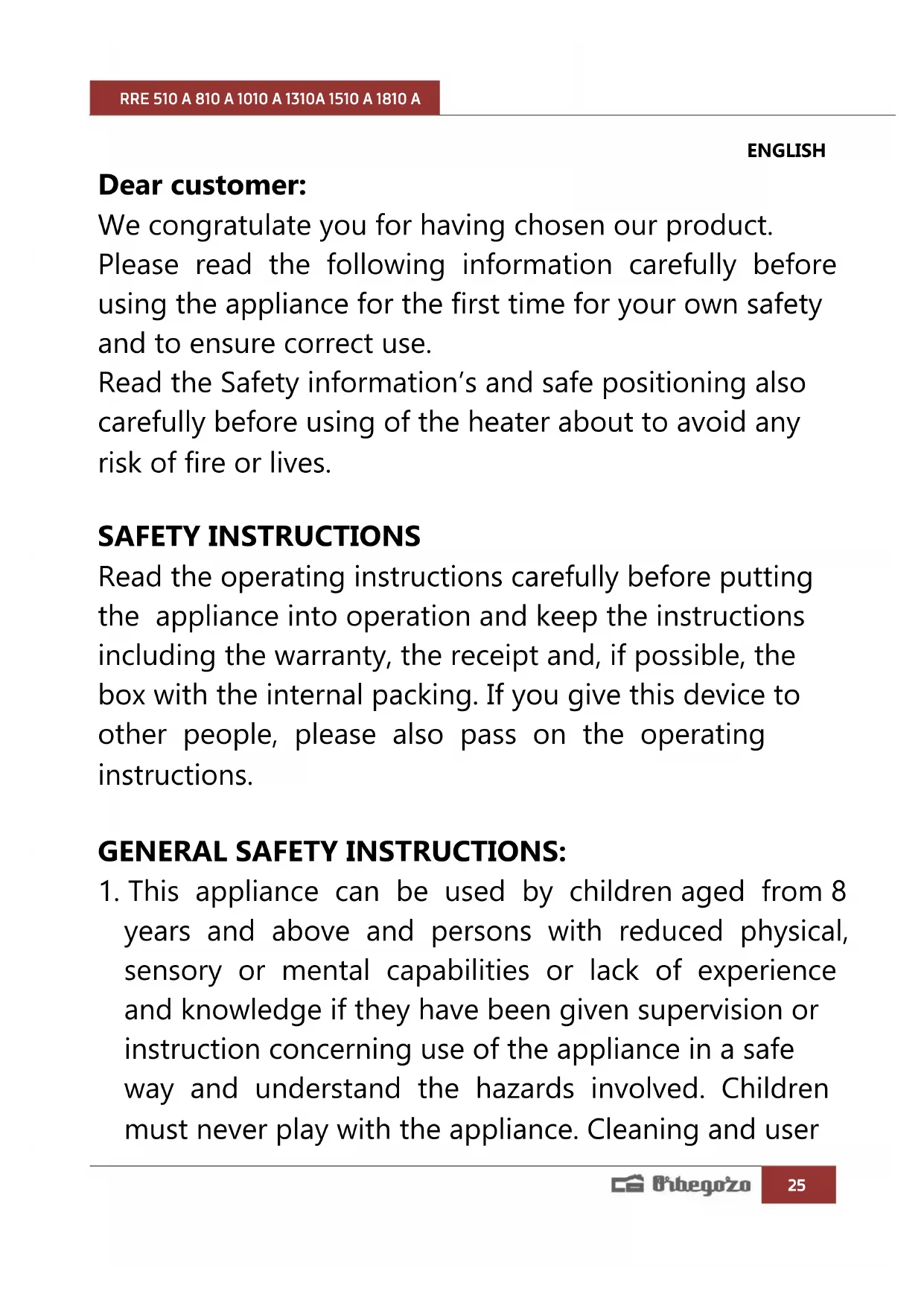
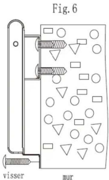
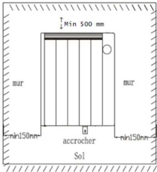
WALL MOUNTING:
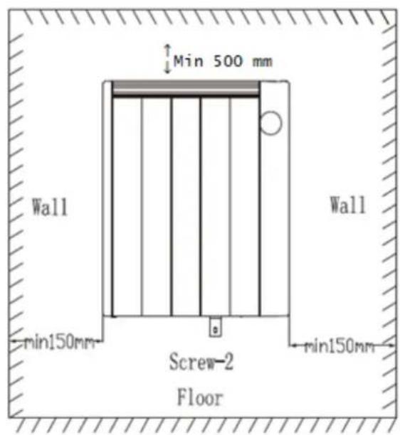
- Follow the minimum safety distances for installation.
- The heater should be placed with a minimum distance 150mm from all objects, walls (fig 2). The distance from the floor must be 220mm and, from the top, 300 mm.
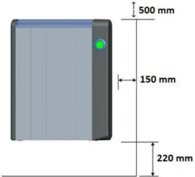
Fig.2
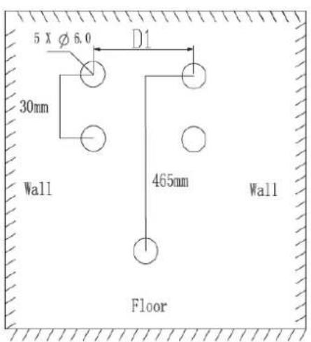
How to mount the heater
Always respect the minimum dimensions shown in the last picture on the next page.
- After selecting the location to install the thermal emitter, place an upper support vertically on the wall and mark the two holes with a spacing of 30 mm. Once done, and depending on its thermal emitter, choose the distance D1 with respect to the previous signals (Fig 3)
| Model | Mounting dimensions (D1) |
| RRE 510 A | 155 mm |
| RRE 810 A | 155 mm |
| RRE 1010 A | 155 mm |
| RRE 1310 A | 155 mm |
| RRE 1510 A | 386 mm |
| RRE 1810 A | 542 mm |
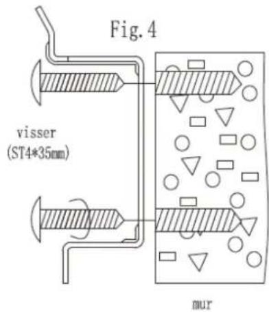
-
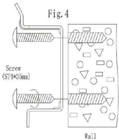
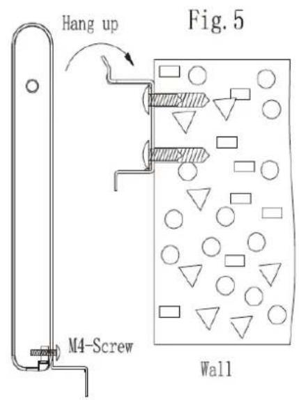
Make four holes, insert wall plugs and screw the upper brackets to the wall (Fig 4)
-
Screw the bottom to the bottom of the emitter.
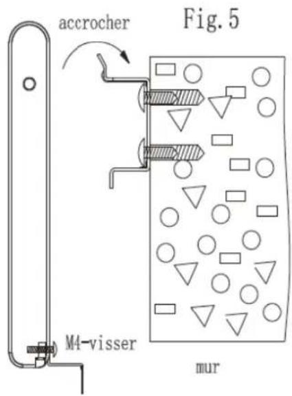
-
Hang the thermal emitter and mark the point to be drilled bottom bracket (Fig 5).
-
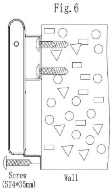
Lift the transmitter and make the hole.
-
Hang transmitter again and screw the bottom bracket to the wall so that the sender is completely fixed (Fig 6)
Fig. 3
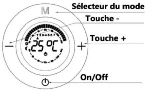
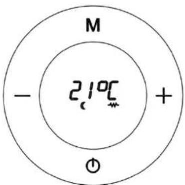
PARTS DESCRIPTION
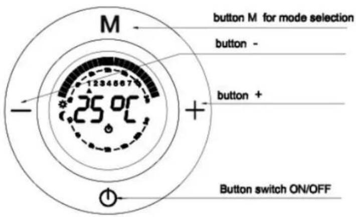
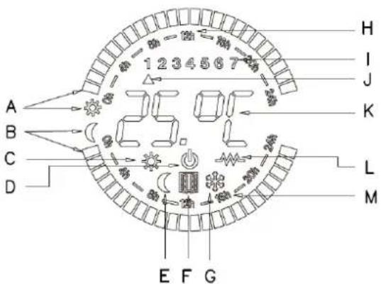
A : The comfort square(sun)
B : The economy square(moon)
C: Comfort Mode symbol
D: OFF symbol
E: Economy Mode Mode symbol
F: Open Window Detection function working indication
G: Anti-frost Mode symbol
H: The clock indication in one day
I: The day of week
J: Indication of the day of week
K: Setting temperature
L: indication of heat on
M: Indication of a time on economy mode
OPERATE INSTRUCTIONS
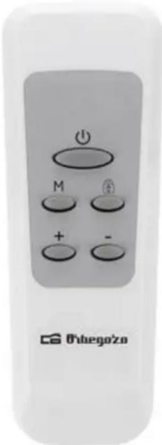
Remote control operate is similar to Manual control operate, except that "Child lock", only located in the remote controller and "Open Window detection" function, located only in the panel.
Comfort temperature and Economy temperature:
The Comfort temperature is the one most frequently used. The Comfort temperature in winter is usually between 20 and 23°C.
The Economy temperature is the temperature at which the appliance makes a moderate consumption. By reducing the set temperature, you can get energy saving.
Recommendations for saving and optimising consumption:
It is highly recommendable to use the Programming mode to adjust the heater to our lifestyle and optimize the power consumption.
It is important each room is heated at the right temperature at all times. A perfect balance between comfort and savings should be achieved.
| Room | Comfort Temperature | Economy Temperature | |
| Day-time | Living room, office | 21-22°C | 18°-19C |
| Night-time | Bedroom | 20°C (When we get up and go to bed) | 17°C (While we are sleeping) |
| Common areas | 18-19°C | 15-16°C |
Switch on the radiator:
Notice: When you switch on the Radiator, the microprocessor reads the internal memory of the appliance and remembers the last mode set by the user.
In the first power on, the memory is empty, reason why the screen will blink constantly until any key is pressed.
Once the heater has been correctly placed and plugged into the socket, please press "Main Power switch" to "I" position to have voltage in it (Fig 7). When connected to the power supply success, OFF symbol will appear on the display (Fig.8)
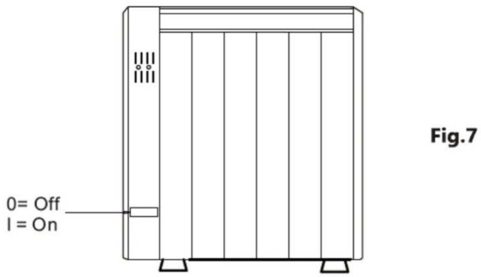
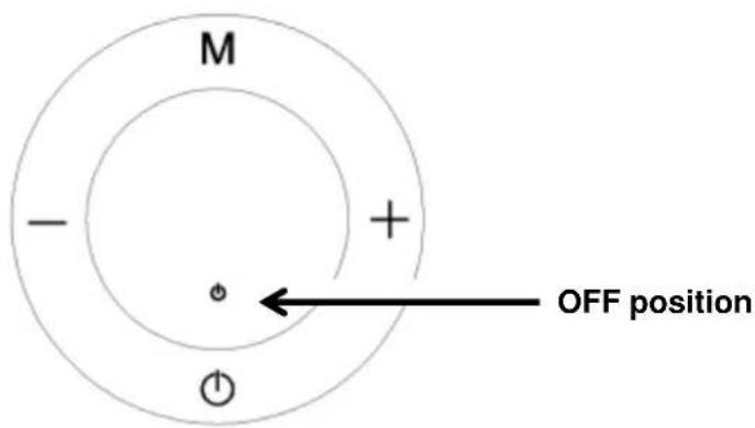
Fig.8
HOW TO CHOOSE WORKING MODE:
Press ⏻ (Fig 9), the appliance will go on and one of the following modes will be displayed (Fig 10, Fig.11, Fig 12, Fig 12, Fig 13):

Fig.9
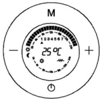
Comfort Mode. (Fig.10)
We set the Comfort temperature according to our requirements by pressing button + or. -
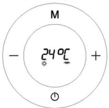
Fig.10
Economy Mode (Fig.11)
We set the Economy temperature according to our requirements by pressing button + or -.
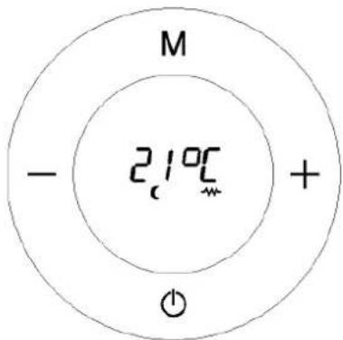
Fig.11
Important: The temperature in Economy mode is always 3^ C lower than Confort mode. Hence, if you change the temperature in any of these two modes, the other one will change automatically too in order to maintain the 3^ C difference.
For example: if we set a Comfort temperature of 24^ C, the Economy temperature automatically falls to 21^ C. In the same way, if we set the temperature of economy mode to 20^ C, Confort one will change automatically to 23^ C.
Programming Mode: (Fig.12)
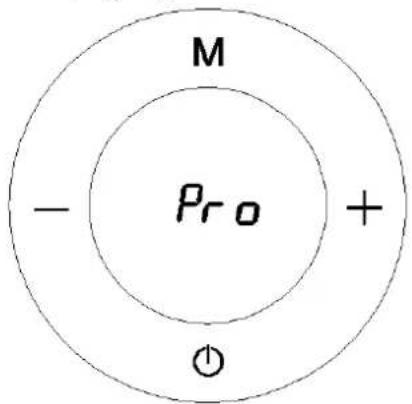
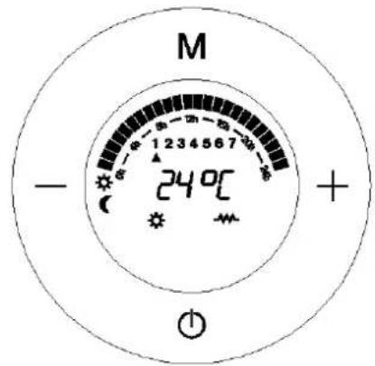
Fig.12
Anti-frost Mode: (Fig.13)
This mode is equivalent to turning Off the device and its function is to avoid the temperature to go below 7^ C. The radiator will turn on only if the temperature falls below 7^ C. This mode cannot be adjusted.
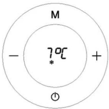
Fig.13
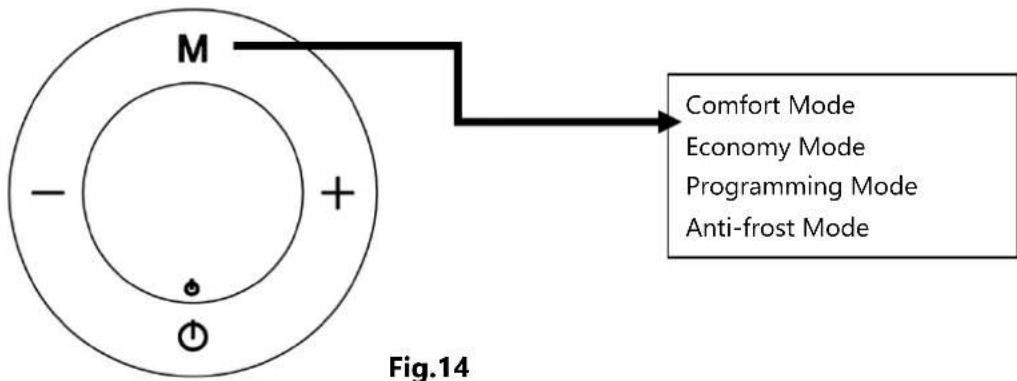
To change mode: Press button M briefly to change mode: (Fig.14)
flowchart
graph TD
    A["Outer Ring"] --> B["M"]
    B --> C["-"]
    B --> D["+"]
    B --> E["Power Source"]
    F["Comfort Mode"] --> G["Economy Mode"]
    F --> H["Programming Mode"]
    F --> I["Anti-frost Mode"]
The symbol is displayed in every mode when the resistance is working.(Fig.15)
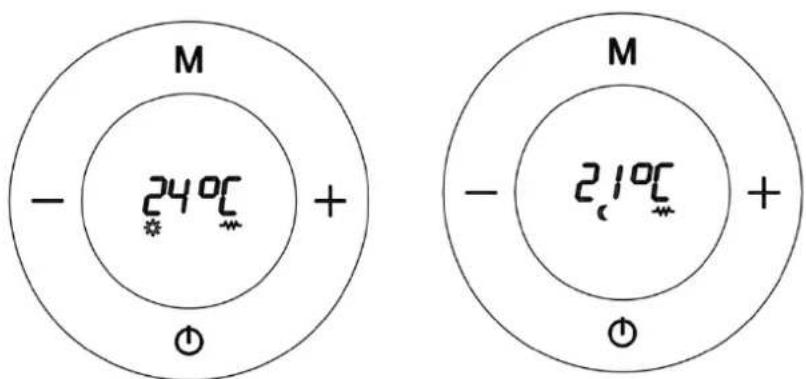
Fig.15
HOW TO PROGRAMME YOUR RADIATOR:
Go to OFF mode as in the picture
Press and hold the button for 5 seconds
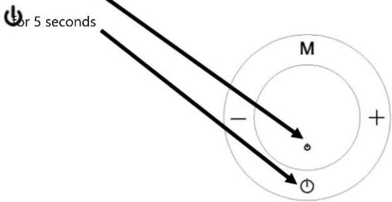
Fig.16
The next display will appear immediately, showing Monday at 00:00 as default (Fig.17). From now on, you have to program the unit in sections of one hour choosing what mode you need in each section: Comfort, Economy or Anti frost (off). Once you have finished the program of 24 hours of Monday, you'll move on automatically to the next day at 00:00 (Monday 1, Tuesday 2. Wednesday 3, Thursday 4, Friday 5, Saturday 6, Sunday 7).
Here is the programming display
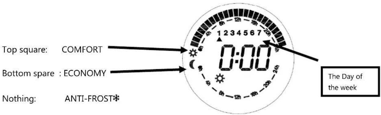
Fig.17
The programming of each hour is carried out as follows:
- Button M is for changing the mode (Comfort, Economy, Anti-frost).
- Button + is for moving to the next hour.
- Button – is for get back to the previous hour.
Let's see a step-by-step example.
After pressing and holding button ⏻ for 5 seconds (Fig.18)
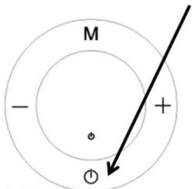
Fig.18
We can see that the display appears (Fig.19). First we must know that programming is to be done hour by hour passing through all the days of the week.
Let's say, for example, we want to program the Comfort mode between 00:00 and 1:00 on Monday.
Press button M until the comfort symbol ⚙ appears (Fig.19), then press button+. By doing this, we have set the Comfort mode between 0:00 and 1:00 and we will move to the next hour section, from 01:00 to 02:00 (Fig.20).
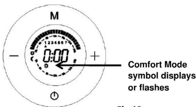
Fig.19
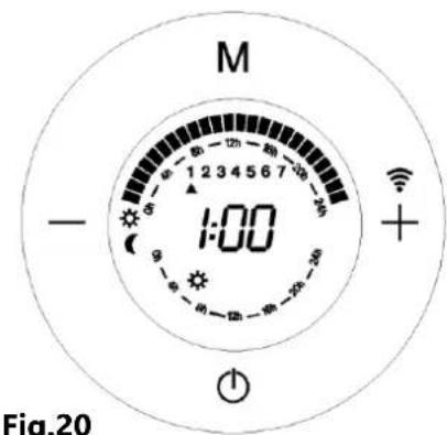
Fig.20
Now we're going to set the Economy mode between 1:00 and 2:00, by simply pressing button M until the economy mode symbol (appears (Fig.21), press button +, by doing this, we have not only set the Economy mode between 1:00 and 2:00, but also the hour will be moving forward again to 2:00, and the time (2:00) appears (Fig.22).
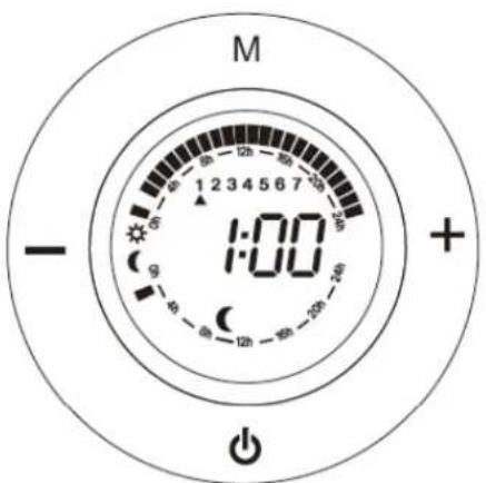
Fig.21
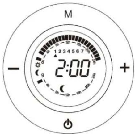
Fig.22
Now we're going to set the Anti-frost mode between 2:00 and 3:00, by simply pressing M until the anti-frost symbol ✝ appears( Fig.23), then press button +. By doing this, we have set the anti-frost mode between 2:00 and 3:00, and we will move to the next section from 02:00 to 03:00. Remember that Anti-Frost mode is equivalent to OFF mode.
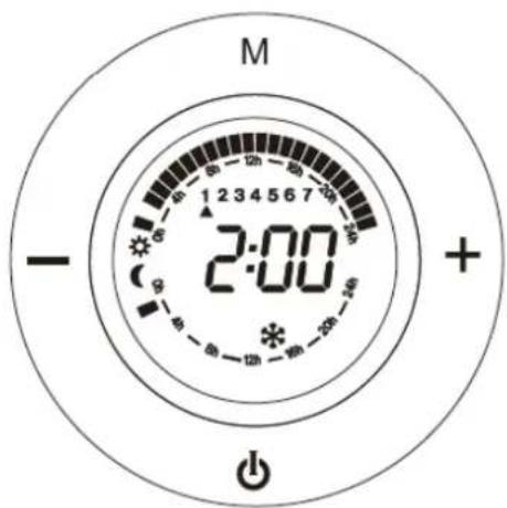
Fig.23
Summary of what we have done. We have programmed the following: the Comfort mode between 0:00 and 1:00; the Economy mode between 1:00 and 2:00, and the Anti-frost mode between 2:00 and 3:00. (Fig.24)
Anti-frost mode 2:00 and 3:00. No square
Comfort mode 0:00 and 1:00. Top square
Economy mode 1:00 and 2:00. Middle square
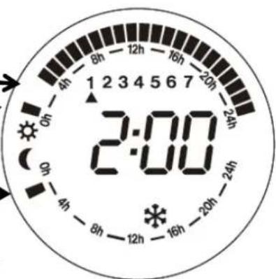
Fig.24
We repeat to do the above procedure, we can successively programme from 0:00 to 23:00 (24 hours) with different modes. , and then we continue with the other days of the week (Monday - Sunday).
How to programme the current day of the week and time:
When we finish 7*24 hours programme, press ⏻, next display appears (Fig.25), this display which is for setting the current day and time.
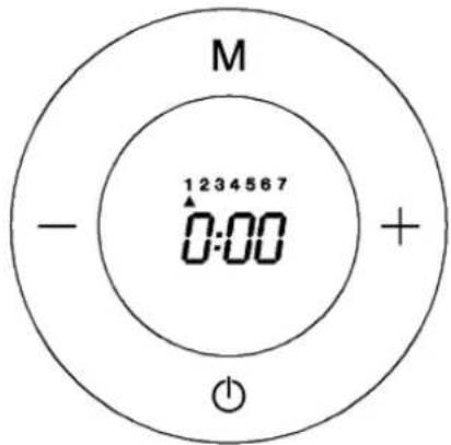
Fig.25
With the button + or – we pass through the days until we find the current day, e.g. Monday, we go to 1, or Wednesday, we using button + or – to 3. (Fig.26)

Fig.26
Now we press button M and the hour display starts to flash. With button + or – we adjust the display to the correct hour, then press button M.
Now the minutes display starts to flash. With button + or - we adjust the display to the correct minute, then press M. The appliance returns to the OFF position.(Fig.27)
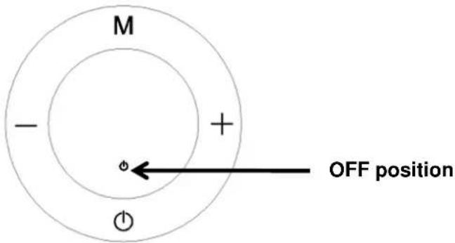
Fig.27
Important:
- If you want to change the mode at any time, use the - button to go back hour by hour and press M to change the mode to the desired one.
- You must schedule 24/7. You can't skip days and leave them unscheduled. If you want to program a day in which the transmitter is switched off at all times, you must select the Antifreeze mode at all hours of that day.
- If you want to exit at any time to set the current day of the week and time, press . Keep in mind that the transmitter will work with the last programming carried out on each day. That is, if you exit the schedule after ending Wednesday (3), the device will work with the schedule you just did between Monday (1) and Wednesday (3) but from Thursday (4) to Sunday (7) it will work with the last programming that has been done in those days.
Now we are ready to use the programming mode. To activate it, all we have to do is switch on the appliance by pressing the button and search for the programming mode with the button M until the next display appears fluctuating between these two. (Fig.28) This means that the programming mode has been activated and is now working. (This is the only way to set the programming mode).
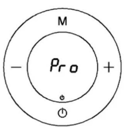
The programming mode is working
Further details
Fig.28
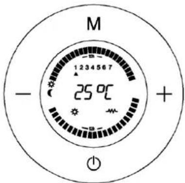
Fig.29
When the programming mode is working,
- On this display, We can see the day, the temperature according to the set mode (Comfort, Economy, Anti-frost) and the squares flash showing the current time if the set mode is the Comfort or Economy Mode.
- This display shows Day 1, Comfort mode temperature 24^ C and the square is flashing at the sun symbol between 0:00 and 1:00, which means it runs on Comfort mode between 0:00 and 1:00 on Monday.
- On this mode, we can set Comfort or Economy temperature according to our requirements by pressing button + or -.
OTHER FUNCTIONS
Temperature Compensation:
Due to the characteristics of the appliance, the temperature is measured on the lower part of the radiator, being perfectly adjusted in relation to the Comfort temperature selected by the user. However, it is also possible to set the "Temperature Compensation" manually.
Room temperature recorded - Comfort temperature indicated = Value...
For example:
22°C in a room temperature measured with the thermometer when the Comfort temperature required on the thermostat (indicated) is 20°C.
The temperature compensation value is 22 - 20 = +2°C
The user must enter +2°C on the temperature compensation menu.
Step 1: Turn the thermostat to the Off position by pressing the button ⏻
Step 2: By pressing button M and holding for for 5 seconds, we will enter this menu where the display shows 0.0
Step 3: Press buttons + or - to adjust fractions of 1^
Step 4: Press button M to confirm and return to the OFF position.
Step 5: Switch on the heater by pressing the button
Child lock :
The user can make sure that nobody changes the set programming, by locking the control panel. This function is very useful for public buildings or for preventing children from tampering with the controles.
It is done by pressing the button on the remote control. To unlock it, press the same button again.
Open Window Detection:
This function makes it possible to detect an open window and automatically activate the anti-freeze operating mode.
- It is done by pressing the button ⏻ and M simultaneously for few seconds, till the symbol 📄 appears.
If a temperature drop is observed in the room during the normal function, the anti-frost mode is automatically activated to save energy consumption, and the symbol 📄 starts to flash continuously. If you press M, the heater will go back to normal function, the symbol 📄 will be stop flashing. Cancelling this function is done by the same way.
Possible thermostat problems:
■ If the thermostat is below -15°C, the screen will display OC.
■ If the thermostat is above 50°C, the screen will display SC.
CLEANING
We recommend keeping electric radiators clean. Dust may appear, which can burn and settle on the wall and on the emitter in the form of streaks or dark areas. These stains are exclusively due to the lack of cleanliness of the electric radiator and the surrounding area.
DISPOSAL OF OLD ELECTRICAL APPLIANCES
The European directive 2012/19/EU on Waste Electrical and Electronic Equipment (WEEE), requires that old household electrical appliances must not be disposed of in the normal unsorted municipal waste stream. Old appliances must be collected separately in order to optimize the recovery and recycling of the materials they contain, and reduce the impact on human health and the environment. The crossed out "wheeled bin" symbol on the product reminds you of your obligation, that when you dispose of the appliance, it must be separately collected. Consumers should contact their local authority or retailer for information concerning the correct disposal of their old appliance.
DECLARATION OF CONFORMITY:
This device complies with the requirements of the Low Voltage Directive 2014/35/EU and the requirements of the EMC directive 2014/30/EU.
GUARANTEE
This appliance is covered and is entitled to the legal guarantee in accordance with the legislation in force from the date of purchase. Keep the purchase receipt to be able to claim your right to the guarantee. To find the closest service to your location, contact through the following web link: https://orbegozo.com/asistencia-tecnica/
For any type of query, doubt or incident, you can contact us through our email shown on the main page of this manual or through our technical assistance service at https://orbegozo.com/contacto/
Orbegozo is not responsible for components and accessories that are subject to wear and tear due to use, as well as perishable compounds or those that have deteriorated due to improper use. Nor will it be held responsible if the owner has technically modified the device. Check the legal conditions on our website.
| INFORMATION REQUIREMENTS FOR LOCAL SPACE HEATERS (EU)2015/1188 | ||||||
| Item | Model identifier | Symbol | Value | Unit | Item | Unit |
| Heat output | Type of heat input, for electric storage local space heaters only (select one) | |||||
| Nominal heat output | RRE 510 A | P_nom | 0.5 | kW | manual heat charge control, with integrated thermostat | No |
| RRE 810 A | P_nom | 0.8 | kW | manual heat charge control with room and/or outdoor temperature feedback | No | |
| RRE 1010 A | P_nom | 1.0 | kW | electronic heat charge control with room and/or outdoor temperature feedback | No | |
| RRE 1310 A | P_nom | 1.3 | kW | fan assisted heat output | No | |
| RRE 1510 A | P_nom | 1.5 | kW | Type of heat output/room temperature control (select one) | ||
| RRE 1810 A | P_nom | 1.8 | kW | single stage heat output and no room temperature control | No | |
| Minimum heat output (indicative) | RRE 510 A | P_nom | 0.5 | kW | Two or more manual stages, no room temperature control | No |
| RRE 810 A | P_nom | 0.8 | kW | with mechanic thermostat room temperature control | No | |
| RRE 1010 A | P_nom | 1.0 | kW | with electronic room temperature control | No | |
| RRE 1310 A | P_nom | 1.3 | kW | electronic room temperature control plus day timer | No | |
| RRE 1510 A | P_nom | 1.5 | kW | electronic room temperature control plus week timer | Yes | |
| RRE 1810 A | P_nom | 1.8 | kW | Other control options (multiple selections possible) | ||
| Maximum continuous heat output | RRE 510 A | P_nom | 0.5 | kW | room temperature control, with presence detection | No |
| RRE 810 A | P_nom | 0.8 | kW | room temperature control, with open window detection | Yes | |
| RRE 1010 A | P_nom | 1.0 | kW | with distance control option | No | |
| RRE 1310 A | P_nom | 1.3 | kW | with adaptive start control | No | |
| RRE 1510 A | P_nom | 1.5 | kW | with working time limitation | Yes | |
| RRE 1810 A | P_nom | 1.8 | kW | with black bulb sensor | No | |
| Auxiliary electricity consumption | ||||||
| At nominal heat output | All models | el_max | 0,000 | kW | ||
| At minimum heat output | All models | el_min | 0,000 | kW | ||
| In standby mode | All models | el_SB | 0,0008 | kW | ||
| Contact details info | SONIFER SA. Avenida de Santiago 86, 30007, Murcia. Spain. | |||||
FRANÇAIS
Cher client :
natural_image
Technical line drawings of a rectangular panel with internal structure and two separate views (no text or symbols)fig 1
fig.1.1
DESCRIPTION DES PIÈCES:
natural_image
Front view of a remote control device with buttons and display (no readable text or symbols)Fig. 10
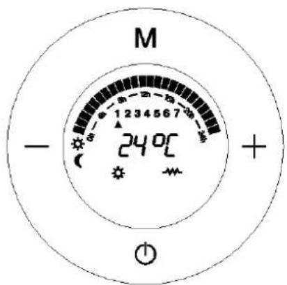
Fig. 12
4. Mode Hors-gel : (Fig. 13)
Fig. 13
chemical
Atomic structure diagram of a diatomic molecule with M and + ions, showing 240°C charge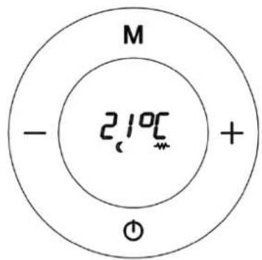
Fig. 15
PROGRAMMATION DU CHAUFFAGE:
Fig. 16
Fig. 18
Fig.20
Fig.21

Fig.22
natural_image
Technical line drawings of a rectangular panel with internal structure and side connectors, shown from top and side views (no text or symbols)fig 1
fig.1.1
natural_image
Diagram of a door handle mechanism with geometric shapes (circles, squares, triangles) and no visible text or symbolsparafuso (ST4*35mm)
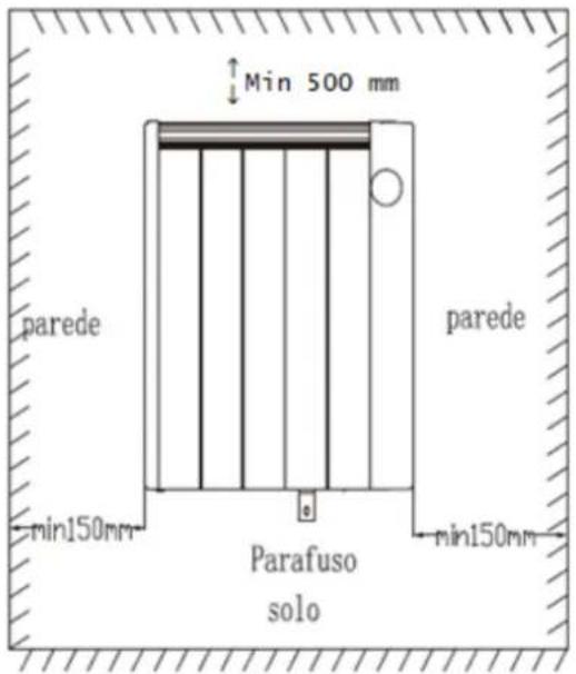

Fig. 12
Modo Anti-gelo: (Fig. 13)
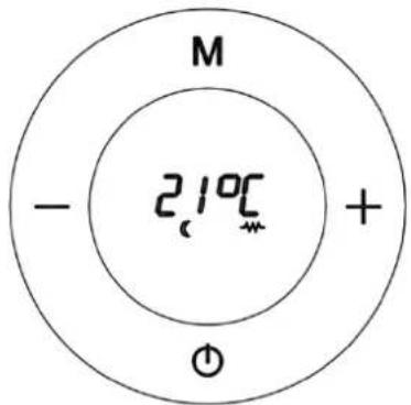
Fig. 15
Fig. 18
natural_image
Technical line drawing of a rectangular panel with vertical grooves and two separate views below (no text or symbols)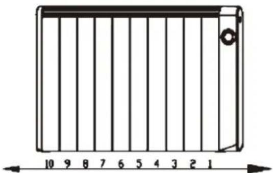
natural_image
Diagram of a rectangular device with vertical bars and a scale bar, no text or symbols presentFig. 1 Fig.1.1
natural_image
White remote control device with buttons labeled M, +, -, and a brand logo (no readable text beyond branding)Fig.13
Canviar mode:
chemical
Diagram of a chemical reaction or electrochemical setup with labeled regions and temperature notationFig.15
COM PROGRAMAR SEU CALEFACTOR:

- RRE 510 A 810 A 1010 A 1310A 1510 A 1810 A
- CÓMO PROGRAMAR SU CALEFACTOR:
- SAFETY INSTRUCTIONS
- GENERAL SAFETY INSTRUCTIONS:
- IMPORTANT SAFETY INSTRUCTIONS:
- INSTALLING INSTRUCTIONS
- This heater can be used freestanding or wall-mounted.
- Free-standing:
- How to install the feet:
- WALL MOUNTING:
- How to mount the heater
- OPERATE INSTRUCTIONS
- HOW TO CHOOSE WORKING MODE:
- Comfort Mode. (Fig.10)
- Economy Mode (Fig.11)
- Anti-frost Mode: (Fig.13)
- HOW TO PROGRAMME YOUR RADIATOR:
- The programming of each hour is carried out as follows:
- How to programme the current day of the week and time:
- Important:
- When the programming mode is working,
- OTHER FUNCTIONS
- Temperature Compensation:
- For example:
- Child lock :
- Open Window Detection:
- Possible thermostat problems:
- CLEANING
- DISPOSAL OF OLD ELECTRICAL APPLIANCES
- DECLARATION OF CONFORMITY:
- GUARANTEE
- Cher client :
- Mode Hors-gel : (Fig. 13)
- PROGRAMMATION DU CHAUFFAGE:
- Modo Anti-gelo: (Fig. 13)
- COM PROGRAMAR SEU CALEFACTOR:
Brand : Orbegozo
Model : RRE 810
Category : Electric heater