SelecTone 314X - Speaker Federal Signal - Free user manual and instructions
Find the device manual for free SelecTone 314X Federal Signal in PDF.

User questions about SelecTone 314X Federal Signal
0 question about this device. Answer the ones you know or ask your own.
Ask a new question about this device
Download the instructions for your Speaker in PDF format for free! Find your manual SelecTone 314X - Federal Signal and take your electronic device back in hand. On this page are published all the documents necessary for the use of your device. SelecTone 314X by Federal Signal.
USER MANUAL SelecTone 314X Federal Signal
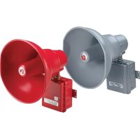
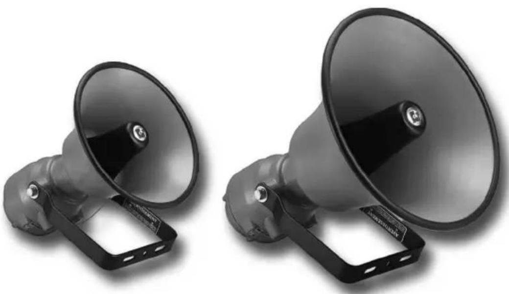
SelectTone™ Models 304X and 314X Explosion-Proof Amplified Speakers
natural_image
Two black megaphones with black plastic caps and black metal brackets, shown from different angles (no text or symbols visible)Installation and Maintenance Instructions

text_image
5yr FEDERAL SIGNAL WARRANTYWarranty – Seller warrants all goods for five years on parts and 2-1/2 years on labor, under the following conditions and exceptions: Seller warrants that all goods of Seller's manufacture will conform to any descriptions thereof for specifications which are expressly made a part of this sales contract and at the time of sale by Seller such goods shall be commercially free from defects in material or workmanship. Seller reserves the right at the Seller's discretion to “Repair and Return” or “Replace” any item deemed defective during the warranty period. This warranty does not cover travel expenses, the cost of specialized equipment for gaining access to the product, or labor charges for removal and reinstallation of the product. This warranty shall be ineffective and shall not apply to goods that have been subjected to misuse, neglect, accident, damage, improper maintenance, or to goods altered or repaired by anyone other than Seller or its authorized representative, or if five years have elapsed from the date of shipment of the goods by Seller with the following exceptions: lamps and strobe tubes are not covered under this warranty. Outdoor warning sirens and controllers manufactured by Federal Warning Systems are warranted for two years on parts and one year on labor. No agent, employee, representative or distributor of Seller has any authority to bind the Seller to any representation, affirmation, or warranty concerning the goods and any such representation, affirmation or warranty shall not be deemed to have become a part of the basics of the sales contract and shall be unenforceable. THE FOREGOING WARRANTIES ARE EXCLUSIVE AND IN LIEU OF ALL OTHER WARRANTIES OR MERCHANTABILITY, FITNESS FOR PURPOSE AND OF ANY OTHER TYPE, WHETHER EXPRESS OR IMPLIED. These warranties shall not apply unless Seller shall be given reasonable opportunity to investigate all claims for allegedly defective goods. Upon Seller's instruction a sample only of allegedly defective goods shall be returned to Seller for its inspection and approval. The basis of all claims for alleged defects in the goods not discoverable upon reasonable inspection thereof pursuant to paragraph 8 hereof must be fully explained in writing and received by Seller within thirty days after Buyer learns of the defect or such claim shall be deemed waived.

FEDERAL SIGNAL
Safety and Security Systems / Industrial
Industrial Systems
2645 Federal Signal Drive • University Park, IL 60484-3167
Tel: 708-534-4756 · Fax: 708-534-4852
Email: elp@federalsignal.com • www.federalsignal-indust.com
Contents
Safety Message to Installers and Users....5
An Overview of the Speakers....6
Unpacking the Speaker....7
Mounting the Speaker....8
Installing the UTM Universal Tone Module 11
Installing the Speaker Connector Card .... 13
Safety Message to Operators....17
Testing and Operating the Speaker....17
Safety Message to Maintenance Personnel 18
Maintaining the Speaker 19
Ordering Replacement Parts....19
Returning the Product for Credit 20
Tables
Table 1 Model 304X specifications ...... 7
Table 2 Model 314X specifications .... 8
Table 3 Tone and Connector Card UL Audibility Ratings ...... 8
Table 4 Model 304X replacement parts ...... 20
Table 5 Model 314X replacement parts ...... 20
Figures
Figure 1 Mounting hole locations and dimensions....9
Figure 2 Dimensions of the Model 304X.... 10
Figure 3 Dimensions of the Model 314X.... 10
Figure 4 Speaker with cover removed .... 12
Figure 5 Speakers connected to EOL device 15
Figure 6 Speakers with supervision relay and connector card .... 16
Safety Message to Installers and Users
WARNING
People's lives depend on your safe installation of our products. It is important to follow all instructions shipped with this product. This device is to be installed by a trained electrician who is thoroughly familiar with the National Electrical Code and/or Canadian Electrical Code and will follow the NEC and/or CEC Guidelines as well as all local codes. This horn should be considered a part of the warning system and not the entire warning system.
The selection of the mounting location for this horn, its controls and the routing of the wiring are to be accomplished under the direction of the Facilities Engineer and the Safety Engineer. In addition, listed below are some other important safety instructions and precautions you should follow:
- Read and understand all instructions before installing, operating, or maintaining this equipment.
- Warning–Explosion Hazard – Do not disconnect equipment unless power has been switched off or the area in known to be non-hazardous.
- Do not connect this unit to the system when power is on.
- Optimum sound distribution will be severely reduced if any objects are in front of the horn. You should ensure that the front of the horn is clear of any obstructions.
- All effective warning horns produce loud sounds which may cause, in certain situations, permanent hearing loss. The device should be installed far enough away from potential listeners to limit their exposure while still maintaining its effectiveness. The OSHA Code of Federal Regulations 1910.95 Noise Standard provides guidelines which may be used regarding permissible noise exposure levels.
-
After installation, ensure that all mounting screws, bolts, and threaded joints are tightened.
-
Establish a procedure to routinely check the signal system for proper activation and operation.
- Any maintenance to the unit MUST be performed by a trained electrician in accordance with NEC Guidelines and local codes.
- Never alter the unit in any manner.
- The nameplate should NOT be obscured, as it contains cautionary and/or other information of importance to maintenance personnel.
- After installation and completion of initial system test, a program for periodic testing of this device must be established. Refer to NFPA 72G, local Fire Codes and the authority having jurisdiction for this information.
- Provide a copy of these instructions to the Safety Engineer, operator(s) and maintenance personnel.
- File these instructions in a safe place and refer to them when maintaining and/or reinstalling the device.
Failure to follow all safety precautions and instructions may result in property damage, serious injury, or death.
An Overview of the Speakers
The Federal Signal Model 304X and 314X Explosion-Proof Amplified Speakers are designed to produce crisp, clear tones in supervised alarm notification systems. Both models are compatible with fire alarm, voice evacuation, suppression supervised control panels, and power boosters.
These amplified speakers can broadcast tones generated by a Tone Card installed into the speaker (the plug-in 32-tone UTM) or by a central tone source in a voice evacuation or paging system. When live public address or voice messages are required, plug-in Federal Signal Connector Cards (AM25CK or AM70CK) interface with the Vrms of the EVAC panel.
The speaker cone and projector are constructed of rugged spun aluminum. The solid-state amplifier circuit is protected in a die-cast aluminum housing. Dust- and moisture-proof gaskets provide protection from the elements. All external surfaces are sealed with gray powder-coat paint. A heavy-duty swivel mount bracket allows the installer to direct the output effectively.
The rugged construction and high output of the Model 304X and 314X make them ideal for use in harsh environments with high ambient noise levels. Both models feature an internal gain control for adjustment to suit the area.
This equipment is suitable for use in Class 1, Division 1, Groups B, C, D; Class I, Division 2, Groups A, B, C, D or non-hazardous locations only.
Unpacking the Speaker
After unpacking the horn, examine it for damage that may have occurred in transit. If the horn has been damaged, do not attempt to install or operate it. File a claim immediately with the carrier, stating the extent of the damage. Carefully check all envelopes, shipping labels, and tags before removing or discarding them. Disposal of all shipping materials must be carried out in accordance with national and local codes and standards. If any parts are missing, please call Federal Signal Customer Support at 708-534-4756 or 877-289-3246.
Table 1 Model 304X specifications
| Operating Voltage: Regulated 24 Vdc (16 Vdc to 33 Vdc) | |
| Maximum Current: 0.83 A | |
| Standby Current: 0.13 A | |
| Operating Temperature: -40 °F to 150 °F (-40 °C to 66 °C) | |
| Net Weight: 15.4 lb (7.0 kg) | |
| Shipping Weight: 22.8 lb (10.4 kg) | |
| Dimensions: | 16.3 in D x 17.0 in H x 13.1 in W414.02 mm D x 431.80 mm H x 332.73 mm W |
| Construction: | Aluminum enclosure and adjustable steelmounting bracket with a powder-coat finish |
Table 2 Model 314X specifications
| Operating Voltage: Regulated 24 Vdc (16 Vdc to 33 Vdc) | |
| Maximum Current: 0.90 A | |
| Standby Current: 0.13 A | |
| Operating Temperature: -40 °F to 150 °F (-40 °C to 66 °C) | |
| Net Weight: 16.4 lb (7.4 kg) | |
| Shipping Weight: 32.4 lb (14.7 kg) | |
| Dimensions: 19.5 in D x 18.8 in H x 16.7 in W495.30 mm D x 477.52 mm H x 424.17 mm W | |
| Ingress Protection: IP65 and NEMA 4X Approved | |
| Construction: Aluminum enclosure and adjustable steelmounting bracket with a powder-coat finish. |
Compatible Tone Modules: TM2 or UTM
Compatible Speaker Connector Cards: AM25CK*, AM70CK*, or 300CKS
*Series A versions of these connector cards are not compatible.
Table 3 Tone and Connector Card UL Audibility Ratings
| Rating: UL dB (A) | Sound Pressure per UL1480 | |
| Speaker: 304X 314X | ||
| Audibility Rating*: | 91 | 97 |
| AM25CK: | 101 | 99 |
| AM70CK: | 101 | 99 |
*Based on TM6, HORN
Mounting the Speaker
The speaker can be mounted on any relatively flat surface capable of supporting the weight of the speaker. Conduit connections can be made to the 1/2" NPT threaded openings at bottom of the housing (see Figure 4 on page 12).
To mount the speaker:
-
Remove the two 1/2"-13 hex-head bolts, flat washers, and lockwashers that secure the mounting bracket to the speaker.
-
Disconnect the lanyard from the mounting bracket at the cotter ring.
WARNING
MOUNTING PRECAUTION — Property damage, serious injury, or death could occur if an accumulation of water, snow, dust, etc. resides in the speaker projector, severely reducing or preventing the operation of this device. Mount the speaker so the speaker projector is pointed horizontally or slightly downward.
- Select the mounting location.
WARNING
MOUNTING PRECAUTION — Property damage, serious injury, or death could occur if any objects are in front of speaker, severely reducing optimum sound distribution. For maximum effectiveness, ensure that the front of the speaker is clear of obstructions.
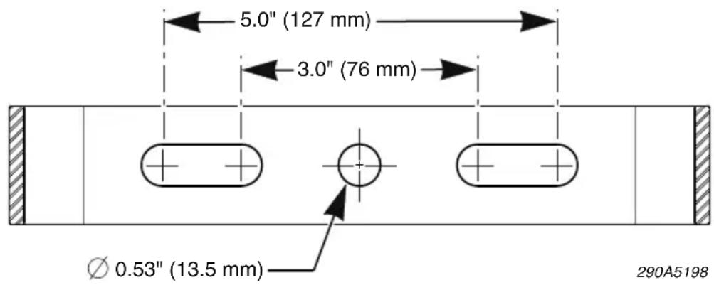
- See Figure 1. Using the mounting bracket as a template, scribe drill position marks on the mounting surface.
Figure 1 Mounting hole locations and dimensions
text_image
5.0" (127 mm) 3.0" (76 mm) Ø 0.53" (13.5 mm) 290A5198NOTICE
DRILLING PRECAUTION — Before drilling holes in any surface, be sure both sides of surface are clear of anything that could be damaged.
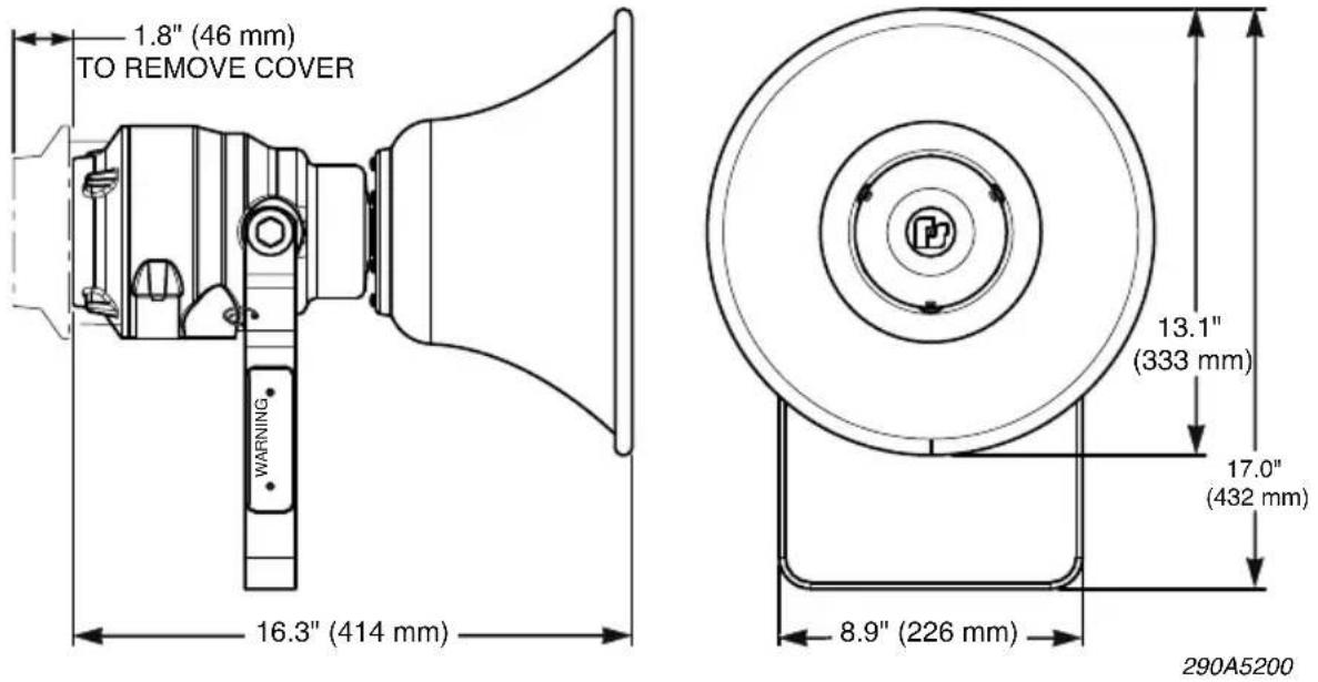
Figure 2 Dimensions of the Model 304X
text_image
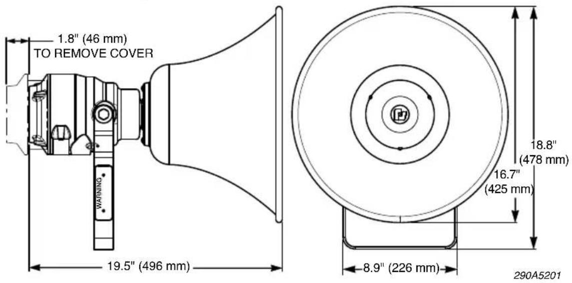
1.8" (46 mm) TO REMOVE COVER WARNING 16.3" (414 mm) 13.1" (333 mm) 17.0" (432 mm) 8.9" (226 mm) 290A5200Figure 3 Dimensions of the Model 314X
text_image
1.8" (46 mm) TO REMOVE COVER 19.5" (496 mm) WARNING 8.9" (226 mm) 18.8" (478 mm) 16.7" (425 mm) 290A5201- Drill holes at the scribed drill-position marks to accommodate the 1/2" diameter bolts.
- Secure the bracket to the mounting surface with the 1/2" diameter hex-head bolts, lockwashers, and hex nuts.
- Reattach the speaker to the mounting bracket with the two 1/2"-13 hex-head bolts, flat washers, and lockwashers.
-
Position the speaker to obtain the required sound coverage, then tighten the bolts securely.
-
Reattach the lanyard to the cotter ring and mounting bracket. Verify that it is securely attached to both the cover and the mounting bracket.
- Route wires through the 1/2" NPT threaded openings into the SelectTone unit in accordance with national and local electrical and fire codes. Wire size depends upon the operating current and the distance from the power source.
See the next sections for instructions on installing the speaker connector card and UTM module, and wiring the speaker.
Installing the UTM Universal Tone Module
WARNING
MISWIRING/ELECTRICAL SUPERVISION — Property damage, serious injury, or death could occur if independent conductors are terminated together; both wires of the same polarity must be used as two separate connections. NFPA 72 requires that the wires be terminated independently to provide electrical supervision of the connection.
WARNING
SHOCK HAZARD — To avoid electrical shock hazards, do not connect wires when power is applied. Failure to heed this warning may cause serious injury or death.
For details, refer to the instructions for the Model UTM Universal Tone Module, doc. No. 2561101.
To install the UTM module in the speaker:
WARNING
DO NOT DAMAGE SEALING SURFACES — Property damage, serious injury, or death could occur if the machined sealing surfaces are damaged on this product. To maintain the effectiveness of the explosion-proof enclosure, be careful to avoid damaging the machined sealing surfaces of cover and housing.
-
Loosen and remove the threaded cover by turning it counterclockwise. Allow the cover to hang by the attached lanyard.
-
Plug the tone card (purchased separately) into the socket as shown in Figure 4.
Figure 4 Speaker with cover removed
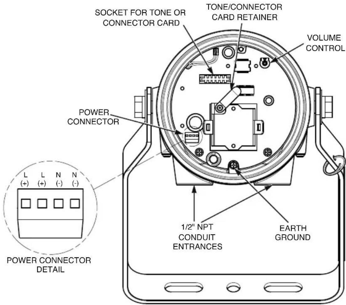
text_image
SOCKET FOR TONE OR CONNECTOR CARD TONE/CONNECTOR CARD RETAINER VOLUME CONTROL POWER CONNECTOR L L N N (+) (+) (-) (-) POWER CONNECTOR DETAIL 1/2" NPT CONDUIT ENTRANCES EARTH GROUND-
Rotate the card retainer into position over the tone card so that it holds the card in place (Figure 4).
-
See Figure 5 on page 15 and Figure 6 on page 16. Connect the positive (+) power-source lead to the terminal block labeled L+.
-
Connect the negative (−) power-source lead to the terminal block labeled N−.
-
Connect the additional positive (L+) and negative (N−) terminal leads to the next speaker or to an end-of-line device.
WARNING
EXPLOSION HAZARD — Property damage, serious injury, or death could occur if the housing is not closed properly. To reduce possibility of explosion, the housing cover must be kept tight while circuits are energized.
- Carefully reinstall the housing cover and tighten it until the cover flange makes contact with the housing.
- To secure the cover, tighten the set screw on the cover. Verify that the mounting bolts are securely tightened.
Installing the Speaker Connector Card
For more details, refer to the instructions for the SelecTone AM25CK and AM70CK Connector Cards, doc. No. 2561183.
WARNING
MISWIRING/ELECTRICAL SUPERVISION FAILURE — Property damage, serious injury, or death could occur if independent conductors are terminated together; both wires of the same polarity must be used as two separate connections. NFPA 72 requires that the wires be terminated independently to provide electrical supervision of the power supply connection and audio lines.
WARNING
SHOCK HAZARD — To avoid electrical shock, do not connect wires when circuits are energized. Failure to heed this warning may cause serious injury or death.
To install the connector card:
- Plug the connector card (purchased separately) into the socket as shown in Figure 4 on page 12.
- Rotate the card retainer into position over the tone card so that it holds the card in place (Figure 4).
-
See Figure 5 on page 15 or Figure 6 on page 16. Connect the positive power-source (+) lead to the terminal labeled L+.
-
Connect the negative (−) power-source lead to the negative terminal labeled N−.
- Connect the additional positive (L+) and negative (N−) terminal-block leads to the next speaker or to a power supervision relay.
- Connect one pair of white leads from the connector card to the audio output of the fire alarm panel.
- Connect the other pair of white leads to the connector card in the next speaker or to a contact on the power supervision relay and an end of line device.
NOTE: Check with the authority having jurisdiction for the proper application of the required EOL resistor and power supervision relay (see Figure 6 on 16).
WARNING
EXPLOSION HAZARD — Property damage, serious injury, or death could occur if the housing is not closed properly. To reduce possibility of explosion, the housing cover must be kept tight while circuits are energized.
-
Carefully reinstall the housing cover and tighten it until the cover flange makes contact with the housing.
-
To secure the cover, tighten the set screw on the cover. Verify that the mounting bolts are securely tightened.
Figure 5 Speakers connected to EOL device
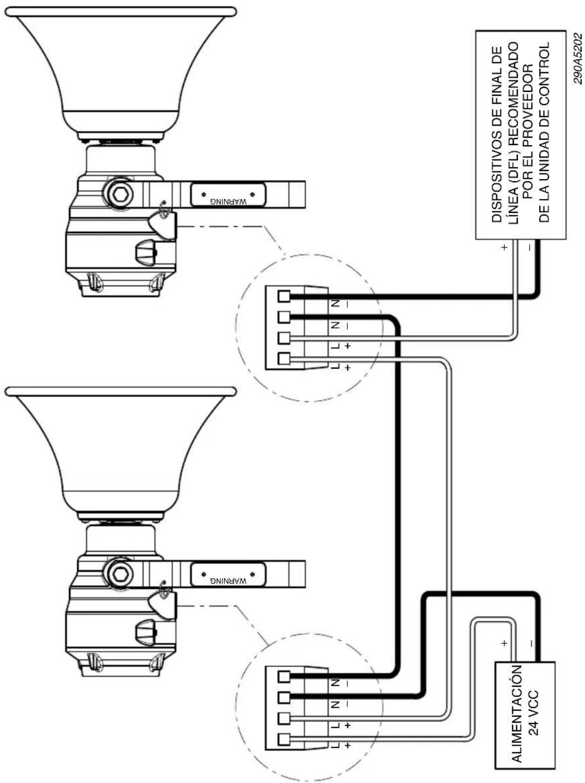
Figure 6 Speakers with supervision relay and connector card
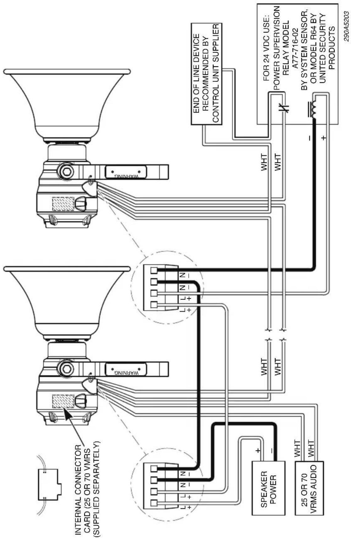
text_image
INTERNAL CONNECTOR CARD (25 OR 70 VMRS (SUPPLIED SEPARATELY) L+ L+ N- N- WARNING L+ L+ N- N- SPEAKER POWER + - WHT WHT 25 OR 70 VRMS AUDIO WHT WHT END OF LINE DEVICE RECOMMENDED BY CONTROL UNIT SUPPLIER WHT WHT FOR 24 VDC USE: POWER SUPERVISION RELAY MODEL A77-716-02 BY SYSTEM SENSOR, OR MODEL R64 BY UNITED SECURITY PRODUCTS 290A5203Safety Message to Operators
WARNING
TESTING/TRAINING PRECAUTIONS — Even if your warning system is operating properly, it may not be completely effective. People may not hear or heed your warning signal. You must recognize this fact and ensure that your warning signal achieves its intended effect through proper test/training sequences within your specific application(s).
Testing and Operating the Speaker
WARNING
SOUND HAZARD — Under certain conditions these devices are capable of producing sounds loud enough to cause hearing damage. Adequate hearing protection should be worn if standing within close proximity to device while testing. Recommendations in the OSHA Sound Level Standard (29 CFR 1910) should not be exceeded.
WARNING
EXPLOSION HAZARD — Property damage, serious injury, or death could occur if the housing is not closed properly. To reduce possibility of explosion, the housing cover must be kept tight while circuits are energized.
After the installation is completed, be sure to test the system to verify that each amplified speaker operates satisfactorily. If the speaker is too loud for the location, adjust the volume as described in these steps:
- Remove the housing cover and insert a slotted electrician-type screwdriver into the volume control shown in Figure 4 on page 12.
- Gently turn the control counter-clockwise to decrease the sound output to the desired loudness.
- Reinstall the housing cover.
After completion of the initial system test, establish a program for periodic testing of this device. Refer to NFPA 72G, local Fire Codes and the authority having jurisdiction for this information.
Provide a copy of these instructions for the Safety Engineer, system operator(s) and maintenance personnel.
Safety Message to Maintenance Personnel
WARNING
Failure to follow all safety precautions and instructions may result in property damage, serious injury, or death to you or others.
- Read and understand all instructions before performing maintenance on this unit.
- Do not perform maintenance on this unit when circuits are energized.
- Do not disconnect the speaker from the system wiring when circuits are energized.
- Periodic checks should be made to ensure that effectiveness of this device has not been reduced because speaker has become clogged with a foreign substance or because objects have been placed in front of the speaker.
- Any maintenance to this unit MUST be performed by a trained electrician in accordance with the National Electrical Code, National Fire Codes, and the local codes.
- Never alter this unit in any manner. Safety in hazardous locations may be jeopardized if additional openings or alterations are made to this device.
- The nameplates, which contain cautionary or other information of importance to maintenance personnel, should not be obscured if exterior of device is painted.
- WARNING: Explosion Hazard — Substitution of components may impair suitability for Class I, Division 2 and Class I, Zone 2.
Failure to follow all safety precautions and instructions may result in property damage, serious injury, or death.
Maintaining the Speaker
WARNING
UNAUTHORIZED REPAIR/SERVICING — Unauthorized repair/servicing of the speaker may result in degradation of performance and/or property damage, serious injury, or death to you or others. If a malfunctioning unit is encountered, do not attempt any field repair/retrofit of parts.
WARNING
EXPLOSION HAZARD — Property damage, serious injury or death could occur if this product's machined sealing surfaces are damaged. To maintain the effectiveness of the explosion-proof enclosure, use caution to avoid damaging the machined surfaces.
Periodically check this device to verify that there are no foreign substances in, or in front of, the speaker which will reduce its effectiveness.
Testing should be periodically performed. Refer to NFPA 72G, local Fire Codes and the authority having jurisdiction for information.
If a volume adjustment or other repair is needed, be sure to refer to the “Safety Message For Maintenance Personnel” on page 18 before proceeding.
Ordering Replacement Parts
Typical spare parts are listed in Tables 4 and 5 on page 20. Due to certification, certain component parts are not available for field replacement. Units with this type of damage must be either replaced entirely or returned to Federal Signal for service.
To order accessories and replacement parts, call Federal Signal Customer Support at 708-534-4756 or 877-289-3246
Table 4 Model 304X replacement parts
| Description Part Number | |
| Amplifier Assembly K200535 | 5-01 |
| Horn Assembly K8593100 | |
| Driver Assembly K8593097 | |
| Cover Assembly K8593098 | |
| Mounting Bracket Assembly | K8593071 |
| 4-Position Connector K1403 | 40 |
Table 5 Model 314X replacement parts
| Description Part Number | |
| Amplifier Assembly K200535 | 5-01 |
| Horn Assembly K8593101 | |
| 4-Position Connector K140340 |
Returning the Product for Credit
Product returns for credit require a return authorization from your local distributor prior to returning the product to Federal Signal. Please contact your distributor for assistance.
A product is qualified to be returned for credit when the following conditions are met:
• Product is resalable and in the original cartons
• Product has not been previously installed
• Product is the current revision
• Product has not been previously repaired
• Product is a standard product
• Product is not a service part
All returns are subject to a re-stock fee.
Defective products that are returned within the warranty period will be repaired or replaced at Federal Signal's sole discretion. Defective products do not include those products with lamp failure.
Circumstances other than those listed above will be addressed on a case-by-case basis.

FEDERAL SIGNAL
Safety and Security Systems / Industrial
Industrial Systems
2645 Federal Signal Drive • University Park, IL 60484-3167
Tel: 708-534-4756 · Fax: 708-534-4852
Email: elp@federalsignal.com • www.federalsignal-indust.com
natural_image
Two black megaphones with black clamps, shown from different angles (no text or symbols visible)Safety and Security Systems / Industrial
Industrial Systems
2645 Federal Signal Drive • University Park, IL 60484-3167
Téléphone: 708-534-4756 • Fax: 708-534-4852
Email: elp@federalsignal.com • www.federalsignal-indust.com • www.fs-isys.com
Contenu
text_image
127 mm (5,0 pouce) 76 mm (3,0 pouce) Ø 13,5 mm (0,53 pouce) 290A7676AVIS
text_image
46 mm (1,8 pouce) POUR RETIRER LE COUVERCLE WARNING 414 mm (16.3 pouce)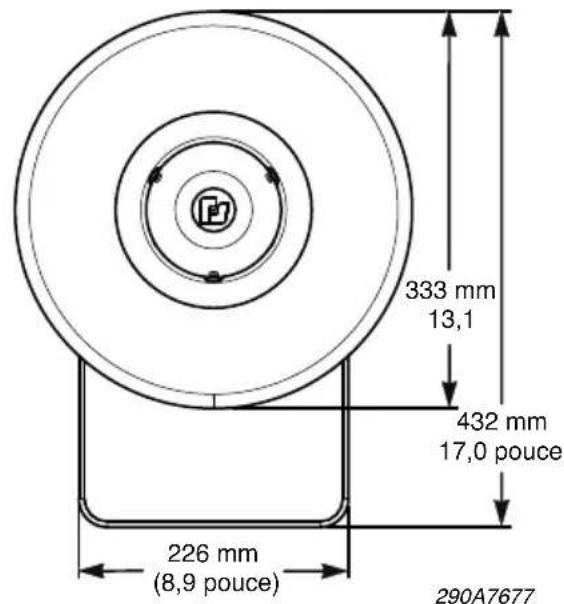
text_image
333 mm 13,1 432 mm 17,0 pouce 226 mm (8,9 pouce) 290A7677Safety and Security Systems / Industrial
Industrial Systems
2645 Federal Signal Drive • University Park, IL 60484-3167
Téléphone: 708-534-4756 • Fax: 708-534-4852
Email: elp@federalsignal.com • www.federalsignal-indust.com • www.fs-isys.com
natural_image
Two black megaphones with black clamps, no visible text or symbols on the devices themselves.Safety and Security Systems / Industrial
Industrial Systems
2645 Federal Signal Drive • University Park, IL 60484-3167
Safety and Security Systems / Industrial
Industrial Systems
2645 Federal Signal Drive • University Park, IL 60484-3167