AudioMaster AM50 - Speaker Federal Signal - Free user manual and instructions
Find the device manual for free AudioMaster AM50 Federal Signal in PDF.

User questions about AudioMaster AM50 Federal Signal
0 question about this device. Answer the ones you know or ask your own.
Ask a new question about this device
Download the instructions for your Speaker in PDF format for free! Find your manual AudioMaster AM50 - Federal Signal and take your electronic device back in hand. On this page are published all the documents necessary for the use of your device. AudioMaster AM50 by Federal Signal.
USER MANUAL AudioMaster AM50 Federal Signal
Address all communications and shipments to:
Failure to follow all safety precautions and instructions may result in property damage, serious injury, or death to you or others.
SAFETY MESSAGE TO INSTALLERS
Peoples lives depend on your safe installation of our products. It is important to follow all instructions shipped with the products. This device is to be installed by a trained electrician who is thoroughly familiar with the National Electric Code and will follow the NEC guidelines as well as local codes.
The selection of the mounting location for the device, its controls and routing of the wiring is to be accomplished under the direction of the Facilities Engineer and the Safety Engineer. In addition, listed below are some other important safety instructions and precautions you should follow:
- This unit should be installed by a qualified electrician in accordance with NFPA 72, and national and local Electrical and Fire Codes, under the direction of the authority having jurisdiction.
- If the unit is not installed in a supervisory system, it must be tested at regular intervals. Refer to NFPA 72 and the local Fire Codes for this information.
- Read and understand all instructions before installing or operating this equipment.
- Do not connect this unit to the system when power is on.
- All effective warning speakers produce loud sounds which may cause, in certain situations, permanent hearing loss. You should take appropriate precautions such as wearing hearing protection.
- After installation, test the sound system to ensure proper operation.
- All effective warning speakers produce loud sounds, which may cause, in certain situations, permanent hearing loss. The device should be installed far enough away from potential listeners to limit their exposure while still maintaining its effectiveness. The OSHA Code of Federal Regulations 1910.95 Noise Standard provides guidelines which may be used regarding permissible noise exposure levels.
- Show these instructions to your Safety Engineer and then file them in a safe place and refer to them when maintaining and/or reinstalling the unit.
- Establish a procedure to routinely check the sound system for proper activation and operation.
- Consult the authority having jurisdiction in your area regarding the proper use and installation of this product.
A. GENERAL.
Model AM50 loudspeakers are Underwriters Laboratories listed for “Fire Protective Signaling Use” (category designation UUMW). The loudspeakers are designed to reproduce electronically generated warning tones that command rapid recognition of emergency
alerting signals. Either a 25 or 70 VRMS AC signal source can be used. In addition, this loudspeaker can reproduce full range voice communication. An in-line capacitor (supplied) provides the isolation necessary for supervisory use.
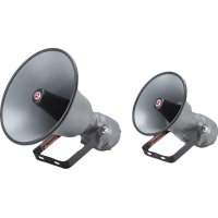
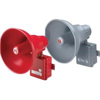
Speaker style: a high-impact plastic re-entrant housing for various applications.
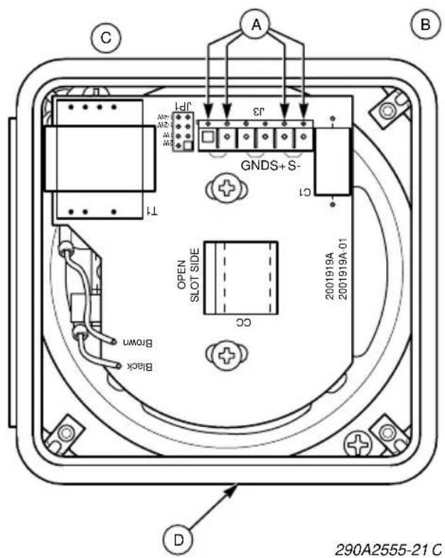
The speaker is supplied with wiring terminals and strain relief for speaker in/out wiring (see figure 1). An optional auxiliary terminal is supplied on the speaker PC board.
B. POWER ADJUSTMENT.
See figures 1 and 2. Multiple power settings are achieved via an adjustable mini jumper. The unit is set at the factory to the 1/4-watt position. To increase the power (volume), remove the supplied mini jumper and place it on the designated pins corresponding to the desired power setting (see table 1). Ensure that the mini jumper is fully seated.
C. INSTALLATION.
WARNING
To avoid electrical shock, do not attempt to install wires when power is on.
- Electrical Connections.
WARNING
An uninsulated section of a single conductor must NOT be looped around a terminal and used as two separate connections. The wire must be severed to provide electrical supervision of the connection.
Use 2 x 14-18 AWG wiring for speaker models.
Strip 1/4" of insulation from all wiring leads. Attach the appropriate wires to the corresponding terminals on the back of the speaker as shown in figures 1, 2, and 3. (Speaker wires are connected to terminals "S+" and "S-".) Tighten the screws to ensure that the wires are firmly held in place.
To select the desired wattage, refer to paragraph B. and see figure 2. Using the mini jumper, set the desired output level (1/4, 1/2, 1, or 2-watt). See table 1.
An optional auxiliary terminal is supplied on the PC board.
- Mounting (see figures 4 and 5).
NOTE
Placement of the Model AM50 speaker within a standard 4 x 4 electrical box requires positioning the rear of the speaker correctly with respect to conduit entryways (see figure 4). Four entryways into the 4 x 4 box cannot be utilized due to the speaker's rear geometry. Be sure to note the site conduit layout prior to speaker installation.
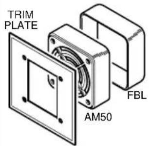
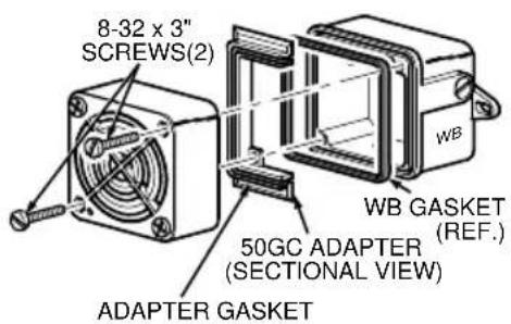
The Re-entrant housings fit either a NB (standard 4 x 4 electrical box) or NBL back box. Re-entrant housings will fit an FBL back box with a FG grille. The Re-entrant housings will also fit a WB back box a trim ring included. An auxiliary trim ring is also supplied (see figure 1) for mounting arrangements.
Use the two #8-32 x 3" (supplied) mounting screws and mount the speaker as shown in figure 5.
D. TESTING/OPERATING.
WARNING
Under certain conditions these devices are capable of producing sounds loud enough to cause hearing damage. Adequate hearing protection should be worn if standing within close proximity to device while testing. Recommendations in the OSHA Sound Level Standard (29 CFR 1910) should not be exceeded.
-
After installation is complete, be sure to test the system to verify that each speaker operates satisfactorily. If it is found that the volume is too low for its location, a higher wattage tap may be selected. Carefully remove the speaker and move the jumper to a higher wattage tap (see figure 2). Reinstall the speaker and retest.
-
After completion of initial system test, establish a program for periodic testing of this device. Refer to NFPA 72, local Fire Codes and the authority having jurisdiction for this information.
-
Provide a copy of these instructions for the Safety Engineer, system operator(s) and maintenance personnel.
SAFETY MESSAGE TO OPERATORS
Even if your warning system is operating properly, it may not be completely effective. People may not see, hear or heed your warning signal. You must recognize this fact and ensure that your warning signal achieves its intended effect through proper testing/training sequences within your specific application(s), or other appropriate actions.
E. MAINTENANCE.
If cleaning of the Model AM50's front face is required, a mild soap solution is recommended as the cleaning agent.
NOTE
Although not advised, if painting/touch-up of the grille model's vinyl face is necessary, a vinyl-based paint is required for coverage.
SAFETY MESSAGE TO MAINTENANCE PERSONNEL
Failure to follow all safety precautions and instructions in this document may result in property damage, serious injury, or death to you or others.
- Read and understand all instructions before performing maintenance on this unit.
- Periodic checks should be made to ensure that effectiveness of this device has not been reduced because speaker has become clogged with a foreign substance or because objects have been placed in front of the speaker.
- Any maintenance to this unit MUST be performed by a trained electrician in accordance with NEC guidelines and local codes.
- Never alter this unit in any manner.
-
Periodically check this device to verify that there are no foreign substances in, or in front of, the speaker which will reduce its effectiveness.
-
Testing should be periodically performed. Refer to NFPA 72, local Fire Codes and the authority having jurisdiction for this information.
- In the event a volume adjustment or other repair is required, be sure to refer to the Safety Message To Maintenance Personnel before proceeding.
F. SERVICE.
WARNING
Unauthorized repair/servicing of the unit may result in degradation of performance and/or property damage, serious injury, or death to you or others. If a malfunctioning unit is encountered, do not attempt any field repair/retrofit of parts.
Federal Signal will service your equipment or provide technical assistance with any problems that cannot be handled locally.
Any units returned to Federal Signal for service, inspection, or repair, must be accompanied by a Return Material Authorization. This R.M.A. can be obtained from the local Distributor or Manufacturer's Representative.
At this time a brief explanation of the service requested or the nature of the malfunction, should be given.
Address all communications and shipments to:
FEDERAL SIGNAL CORPORATION
Electrical Products Division
Service Department
2645 Federal Signal Drive
University Park, IL 60466-3195
Electrical Products Division
Service Department
2645 Federal Signal Drive
University Park, IL 60466-3195
CONSIGNES D'INSTALLATION POUR LE MODÈLE DE HAUT-PARLEURS AM50 RÉGLABLES
▲ AVERTISSEMENT
Electrical Products Division
Service Department
2645 Federal Signal Drive
University Park, IL 60466-3195
Table 1.
| Tap Power UL Sound Level @ 10' dB(A) | |
| 1/4 Watt 1/4 Watt 78 | |
| 1/2 Watt 1/2 Watt 81 | |
| 1 Watt 1 Watt 84 | |
| 2 Watt 2 Watt 87 |
Tabla 1.
| Toma Potencia Nivel de sonido @ 10' dB(A) | ||
| 1/4 Vatio 1/4 Vatio 78 | ||
| 1/2 Vatio 1/2 Vatio 81 | ||
| 1 Vatio 1 Vatio 84 | ||
| 2 Vatio 2 Vatio 87 | ||
Tableau 1.
| Prise Puissance UL Puissance acoustique @ 10' dB(A) | |
| 1/4 Watt 1/4 Watt 78 | |
| 1/2 Watt 1/2 Watt 81 | |
| 1 Watt 1 Watt 84 | |
| 2 Watt 2 Watt 87 | |
1
text_image
C A B JF1 3 GNDS+S- CT TI OPEN SLOT SIDE 2001919A 2001919A-01 CC Brown Black D 290A2555-21 CEnglish
A. In/Out speaker wiring terminals
Terminal wire size to be 14-18 AWG copper solid/stranded Screw torque max. 7 lbs.-in
B. Re-entrant housing
C. This side faces wall
D. Auxiliary trim ring
Español
A. Mini Jumper
B. In/out speaker power wiring strain reliefs
C. Optional auxiliary terminal
Español
A. Speaker 25 or 70 VRMS signal source
B. First speaker
C. Last speaker
D. EOL device to be supplied by listed fire alarm control panel manufacturer.
Español
text_image
NB OR NBL TRIM RING AM50A
text_image
TRIM PLATE FBL AM50B
text_image
8-32 x 3" SCREWS(2) WB WB GASKET (REF.) 50GC ADAPTER (SECTIONAL VIEW) ADAPTER GASKET©
290A3021B
English
A. Re-entrant housing with trim ring and NB or NBL back box
B. Re-entrant housing with FG Grille and FBL back box (flush mounting)
C. Re-entrant housing with trim ring and WB back box