TPSmall - Humidifier HONEYWELL - Free user manual and instructions
Find the device manual for free TPSmall HONEYWELL in PDF.
| Product type | Dehumidifier |
| Brand | Honeywell |
| Model | TPSmall |
| Refrigerant gas | R290 (max charge: 0.05 kg) |
| Operating temperature range | 5°C to 32°C |
| Fan speeds | 2 (High and Low) |
| Timer | 0.5 to 24 hours |
| Continuous mode | Yes |
| Sleep mode | Yes |
| Automatic restart | Yes |
| Auto defrost | Yes |
| Drainage system | Tank or continuous (1m hose included) |
| Full tank alert | Yes (visual and audible) |
| Filter alert | Yes |
| Dust filter | Washable (recommended every 2 weeks) |
| Cord winder | Yes |
| Carry handle | Yes |
| Casters | Yes |
| Control panel | Electronic with LED display |
| Splash-proof protection | Yes |
| Foam float | Yes (water level detection) |
| Safety | Auto shut-off when full, auto restart, frost protection |
| Included accessories | Continuous drain hose (1m), cord winder |
Frequently Asked Questions - TPSmall HONEYWELL
User questions about TPSmall HONEYWELL
0 question about this device. Answer the ones you know or ask your own.
Ask a new question about this device
Download the instructions for your Humidifier in PDF format for free! Find your manual TPSmall - HONEYWELL and take your electronic device back in hand. On this page are published all the documents necessary for the use of your device. TPSmall by HONEYWELL.
USER MANUAL TPSmall HONEYWELL
Read and save these instructions before use
natural_image
Line drawing of a Honeywell air purifier with control panel and digital display (no text or symbols on device body)SE Avfuktare
Thank you for purchasing a Honeywell Dehumidifier. This User Manual is intended to provide you with important information needed to set up, operate, maintain and troubleshoot this product.
SAFETY RULES
WARNING -- READ AND SAVE THESE INSTRUCTIONS BEFORE USING THIS PRODUCT.
The use of electrical products may create hazards that include, but are not limited to injury, fire, electrical shock. Failure to follow these instructions may damage and/or impair its operation and void the warranty. In case there is any inconsistency or conflict between the English version and any other language version of the content of this material, the English version shall prevail.
When using electrical appliances, basic safety precautions should always be followed:
- DO NOT touch the dehumidifier or the electrical plug with wet hands.
- Check the household voltage to ensure it matches the appliance's specification.
- Before operating, remove all packaging material and check for any damage that may have occurred during shipping.
- DO NOT operate any product with a damaged cord or plug.
- DO NOT use an extension cord with this appliance.
- DO NOT run power cord under carpeting, or cover it with rugs or runners. Keep the cord away from areas where it may be tripped over.
• Always unplug the dehumidifier before emptying the water tank. - The water collected in the tank must be discarded. The water should never be used for drinking.
- Always unplug the dehumidifier and remove the water from the water tank before cleaning, servicing or relocating the unit.
- Remove the power cord from the electrical receptacle by grasping and pulling on the power cord plug-end only, never pull the cord.
- This appliance has been manufactured for use in domestic environments and must not be used for other purposes.
- DO NOT use the product in areas where gasoline, paint or other flammable goods and objects are used or stored.
- This dehumidifier is designed for indoor residential applications only. It should not be used for commercial or industrial applications.
-
DO NOT attempt to repair or adjust any electrical or mechanical functions of the dehumidifier, as this may cause danger and void the warranty.
-
DO NOT cover the air inlet or outlet on the appliance as this may cause the unit to fail.
- DO NOT insert or allow objects to enter any ventilation or exhaust opening as this may damage the product and could cause electrical shock or fire.
- If the supply cord is damaged, it must be replaced by the manufacturer, its service agent or similarly qualified persons in order to avoid a hazard.
- DO NOT let children play with this appliance, packaging or included plastic bag.
- If the unit is damaged or it malfunctions, do not continue to operate it. Unplug the product from the electrical outlet. Refer to the troubleshooting section and contact the customer support center.
• Always place the dehumidifier on a leveled floor. - Never install the product near a bathtub or any water container.
- Store in a dry area, away from direct sunlight, when not in use.
- This appliance and its packaging materials are not intended for use by persons (including children or elderly) with reduced physical, sensory or mental capabilities, or lack of experience and knowledge, unless they have been given supervision or instructions concerning the use of the appliance by a person responsible for their safety.
- Always grip the top handle and keep the unit upright when transporting from room to room – DO NOT tilt the product on its side or upside-down.
- If the dehumidifier was transported tilted on its side, you must position it upright again and wait at least 4 hours before using it.
- WARNING: To reduce the risk of fire or electric shock, do not use this appliance with any solid state speed control device.

This marking indicates that this product should not be disposed with other household wastes throughout the EU. To prevent possible harm to the environment or human health from uncontrolled waste disposal, recycle it responsibly to promote the sustainable reuse of material resources. To return your used device, please use the return and collection systems or contact the retailer where the product was purchased. They can take this product for environmental safe recycling.
TP-BIG and TP-SMALL - R290
| SYMBOL NOTE EXPLANATION | ||
 Caution, risk of fire, R290 Caution, risk of fire, R290 | WARNING | This symbol shows that this appliance uses a flammable refrigerant. If the refrigerant is leaked and exposed to an external ignition source, there is a risk of fire. |
 | CAUTION | This symbol shows that the operation manual should be read carefully. |
 | CAUTION | This symbol shows that a service personnel should be handling this equipment with reference to the installation manual. |
 | CAUTION | This symbol shows that information is available such as the operating manual or installation manual. |
Additional warnings for appliances with R290 refrigerant gas.
- Read the instruction carefully before using the appliance.
- When defrosting or cleaning, do not use any method other than those recommended by the manufacturer.
- Do not place the appliance in a room with continuous sources of ignition (e.g. open flame, operating gas appliance or working electrical heater).
- Do not pierce and do not burn.
- Do not perforate any part of the refrigerant circuit.
• Refrigerant gas may be odorless. - The appliance must be installed, used and stored in an area that is greater than 4 m^2 .
- Accumulation of possible refrigerant leaks in an unventilated room could lead to fire or explosion should the refrigerant come in contact with electric heaters, stoves or other sources of ignition.
- The appliance must be stored in a way to prevent mechanical damage.
- Only individuals authorized by an accredited organization certifying their competence to handle refrigerants in compliance with industry legislation should work on the refrigerant circuit.
• R290 refrigerant gas complies with European environmental directives. - This appliance contains a certain number of grams (see rating label at the back of the unit) of R290 refrigerant gas. The maximum refrigerant charge amount is 0.05 kg.

Repair must be performed based on the recommendations from the manufacturer. Maintenance and repair that requires the assistance of other qualified personnel must be performed under the supervision of specialists in the use of flammable refrigerants.
HOW A DEHUMIDIFIER WORKS
When the dehumidifier is switched ON, a fan pulls moisture-laden air into the dehumidifier where it passes through dehumidifying coils inside the unit. These coils condense moisture from the air and collect it in the water tank. The dry air is then exhausted from the dehumidifier. The air flows through the air vents of the dehumidifier into the room as dry, warm air.
IMPORTANT: The dehumidifier is designed to operate between 41^ F ( 5^ C) and 89^ F ( 32^ C). The dehumidifier's performance may be greatly reduced if room temperature is beyond this temperature range.
SELECTING A LOCATION - IMPORTANT
- Before using the dehumidifier, place the unit UPRIGHT for at least 1 hour before use to allow the refrigerant to stabilize. If the unit was tilted on its side or upside-down during transportation, set the unit upright for 4 hours before use.
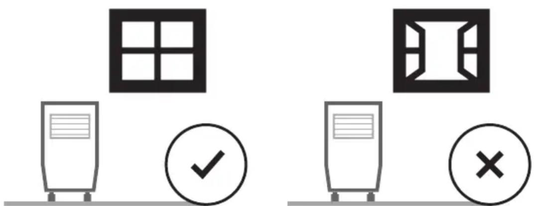
- For optimal efficiency, the dehumidifier must be operated in an enclosed area. Keep all doors, windows and other outside entrances to the room closed.
SELECTING A LOCATION - IMPORTANT (CONTINUED)
- Place the dehumidifier in an area where the temperature will not drop below 41^ (5°C)
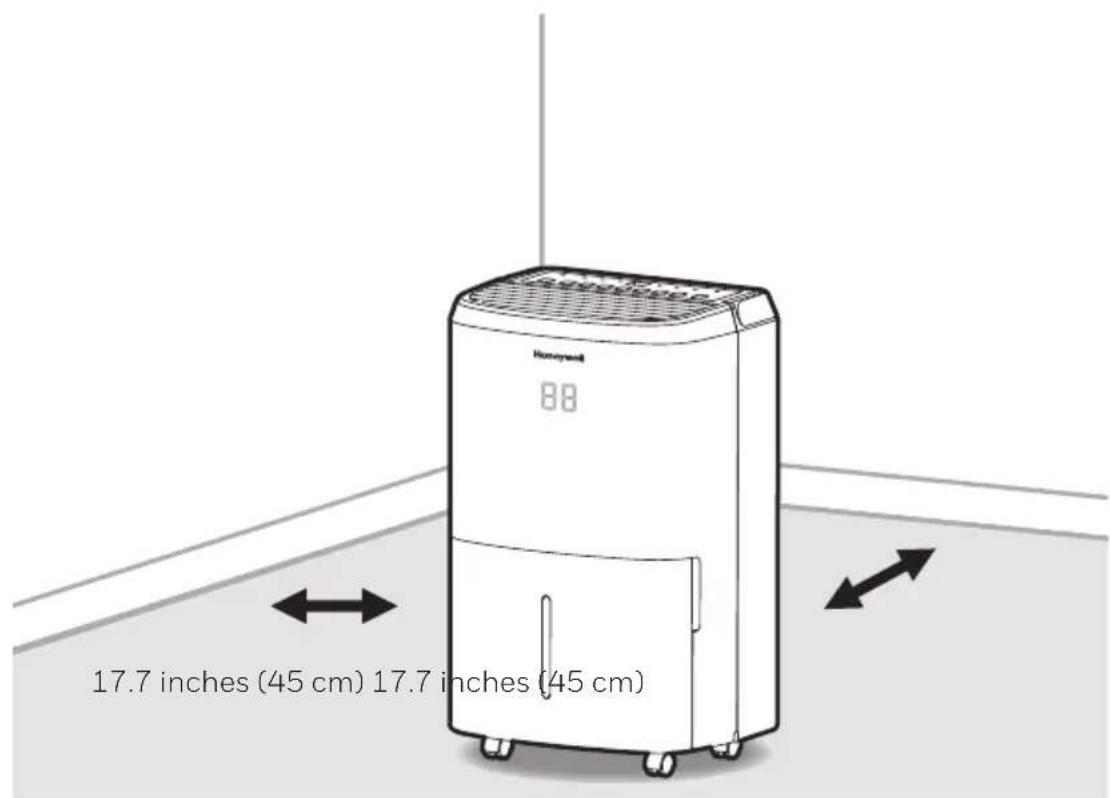
- Place the dehumidifier at least 17.7 inches (45 cm) away from other objects (e.g. curtains or furniture) that may restrict airflow from the back or through the air vents of the unit.
• The dehumidifier must be positioned on a level floor.
IMPORTANT: The effectiveness of the dehumidifier can be influenced by different factors. One factor is the rate at which new, moisture-laden air enters the room and the amount of air circulating in and out of the area to be dehumidified. For example, if a door to a basement is constantly opened, letting new, moisture-laden air into the room, dehumidification will take longer than if the door was kept closed. If the dehumidifier is in a room with a storage closet or cabinets, it will have little or no effect in drying the inside of the storage closet or cabinets unless there is adequate circulation of air in and out of these spaces. To dehumidify these spaces, open the storage door or cabinet doors to allow air circulation. You may find that installing a second dehumidifier may be required for larger enclosed areas.
UNPACKAGING THE DEHUMIDIFIER
- This Dehumidifier is packaged with a colored or transparent tape to secure some parts during transportation. Remove the colored or transparent packaging tape from the unit.
- Gently pull the water tank from out of the dehumidifier
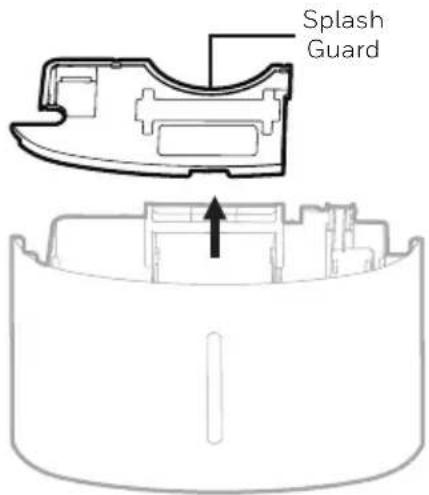
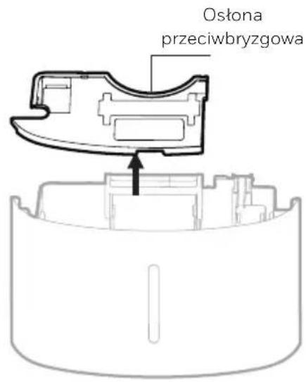
- Remove the splash guard from the top part of the water tank
- Take out the power plug, drain hose and other accessories, which is placed inside the tank of the dehumidifier.
- Once all accessories have been removed, replace the splash guard onto the top part of the water tank. Make sure that the tank is properly positioned.
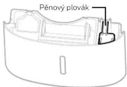
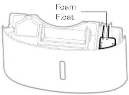
- There is a Foam Float inside the water tank that senses the water level to automatically stop dehumidification when the water tank is full. Make sure the Foam Float is positioned correctly inside the water tank by ensuring it lies level with the top edge of the water tank.
DO NOT REMOVE THIS FOAM FLOAT.
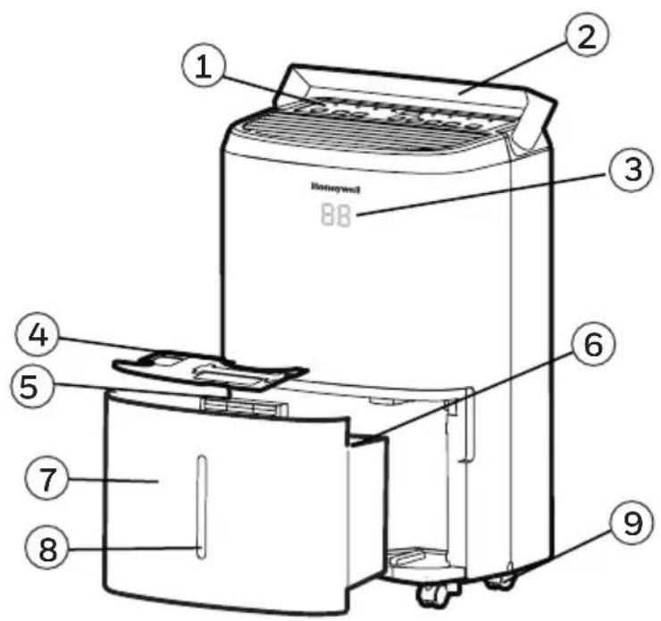
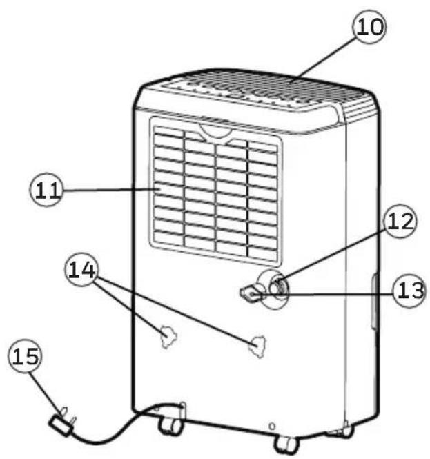
1) Control Panel 10) Dehumidified Air Exhaust Vent
2) Handle 11) Washable Dust Filter
3) LED Display 12) Direct Drain Outlet
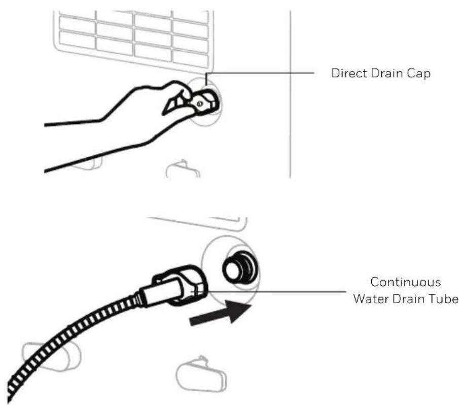
4) Splash Guard 13) Direct Drain Cap
5) Water Tank Handle 14) Mounting Holes for Cord Winders
6) Foam Float 15) Power Cord & Plug
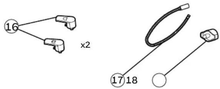
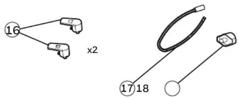
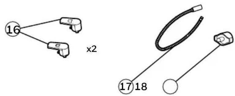
7) Water Tank 16) Cord Winders
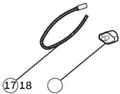
8) Water Level Indicator 17) Continuous Water Drain Tube
9) Casters 18) Continuous Water Drain Cap
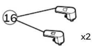
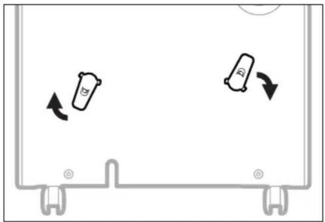
Once you have removed the cord winder accessories from the water tank - follow the steps below.
Step 1: Line up the cord winder pieces to the mounting holes.
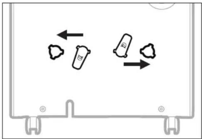
natural_image
Diagram showing three cylindrical objects with arrows indicating movement or flow, enclosed in a rectangular frame (no text or symbols)Step 2: Rotate 45-degrees clock-wise.
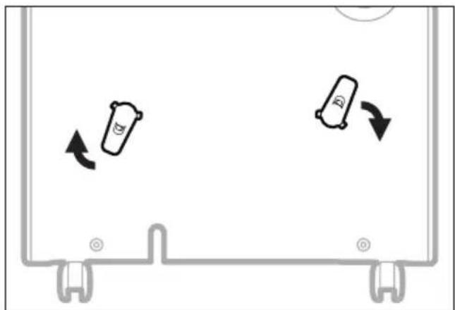
natural_image
Diagram showing two cylindrical objects moving in a container with directional arrows indicating movement (no text or symbols)Step 3: Once you hear "click", then you know the cord winder is ready for use.
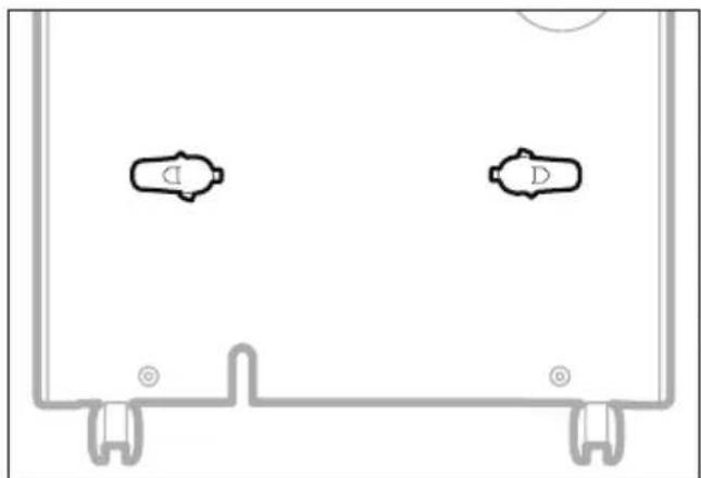
natural_image
Pure diagram of two identical mechanical components with mounting brackets and a circular symbol, no text or labels present.NOTE: Once the installation of the cord winder has been completed. The cord winder cannot be removed. The installation is permanent.
CONTROL PANEL
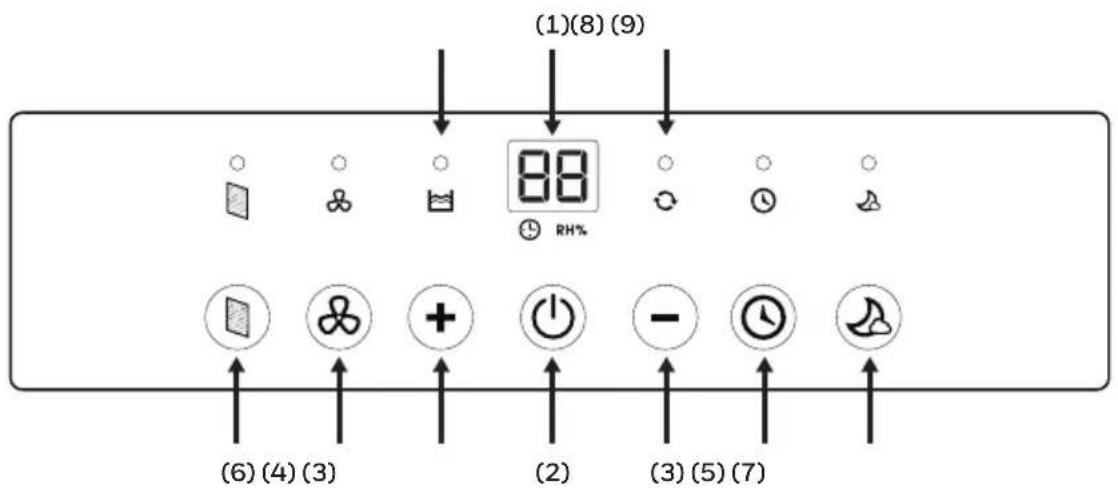
1) Display Screen 6) Filter Alert
2) Power Control 7) Sleep Mode
3) Humidity / Timer Set Controls 8) Water Full Indicator Light
4) Fan Speed Control 9) Continuous Operation Light
5) Timer Control
FUNCTION BUTTONS
POWER CONTROL

Press to switch the dehumidifier ON or OFF.
HUMIDITY CONTROL SETTING

RH%
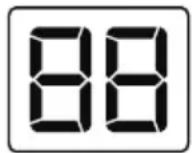
When the unit is switched ON, the Display Screen shows the current humidity percentage.
Press + or — to select your preferred humidity level. The humidity is adjusted in increments of 5% by pressing + or —. The adjustable Relative Humidity (RH) range is between 30% RH to 90% RH. Ten seconds after setting the preferred humidity setting, the display will revert back to displaying the current humidity.
Recommended Settings: It is recommended to leave the unit running at 30% humidity at High Fan Speed during the first 2 to 3 days until damp odors are removed. After a few days when the Relative Humidity has been reduced to a more comfortable level, press + or — to choose a higher RH% that maintains a comfortable humidity level thereafter. A recommended healthy humidity level is between 40% and 50%.
NOTE: The humidity sensor senses current humidity in the surrounding area. It is normal for a few degrees of variance to the humidity sensitivity from the sensor.
CONTINUOUS MODE
To activate the Continuous Mode, press the — button on the Display Screen until [O] appears. The ○ indicator light will be illuminated. The unit will run continuously.
WATER TANK FULL ALERT
When the Water Tank is full, the 📋 indicator will be illuminated. The unit will beep for 3 seconds. The compressor will shut off, and the fan will stop for a few minutes. To switch off the 📋 indicator light, empty the water tank and when replacing it ensure the tank is secured properly in place.
IMPORTANT: Do not place the Water Tank on the floor when full. In case of an uneven base which may cause the tank to spillover.
FUNCTION BUTTONS (CONTINUED)
TIMER CONTROL
The dehumidifier can be set to automatically switch ON or OFF for a selected period of time (between 0.5-24 hour intervals). The Timer hours selection is displayed on the Display Screen.
NOTE: Before setting the Timer control, make sure there is power to the unit.
Auto-Off Timer:
While the unit is running, press ⏻, the timer ⏻ indicator light will flash, press + or — to select the number of hours (0.5-24 hours) you want the unit to run before it switches off. In 5 seconds without the operation, the Timer start function, the timer ⏻ indicator light is illuminated. Timer must be set again after each use.
Auto-On Timer:
When unit is in Standby Mode, press 🔒, the timer 🔒 indicator light will flash, press + or — to select the number of hours (0.5-24 hours) until you want the unit to automatically start running. In 5 seconds without the operation, the Timer start function, the timer 🔒 indicator light is illuminated. The previous fan speed and humidity setting will be maintained. The unit will turn on and continue running until the water tank is full (unless the unit is set up for continuous draining) or until you switch it off manually. Timer must be set again after each use.
NOTE: To cancel any Timer settings, simply press 📁 again, and the timer 📁 indicator light will disappear.
NOTE: The solid red Power light indicates the unit is on Standby Mode.
FAN SPEED CONTROL
There are two fan speeds - High and Low. When, the ✕ indicator light is illuminated, the unit is operating on High speed. When the ✕ indicator light is off, and the unit is on - the unit is operating on Low speed.
FILTER ALERT
When the Filter Alert Light is ON, it is time to clean the filter. Switch the unit OFF and carefully remove the filter from the unit and clean. Replace the filter and switch ON the unit.
The Filter Alert Light should not be illuminated until the filter requires cleaning again. The frequency of filter cleaning depends on room environment conditions. Some rooms may require changing more frequently than others.
FUNCTION BUTTONS (CONTINUED)
SLEEP MODE

The LED display brightness will be reduced when the unit is in Sleep Mode. Press the 🎨 to activate the Sleep Mode. When Sleep Mode is activated the 🎨 indicator light will be illuminated. There is a one-minute window period in which you can adjust the settings such as humidity and fan speed. After one minute has lapsed, the top display will shut off, except the 🎨 indicator light. Press any button to deactivate Sleep Mode.
AUTO RESTART FUNCTION
This unit is equipped with an Auto Restart feature. When there is a power outage, the dehumidifier will automatically resume all its previous settings upon regaining power.
AUTOMATIC DEFROST
Frost may build up on the internal coils of the unit. When there is frost build up, the internal compressor will turn off and the fan will continue to run until the frost has melted. Once the internal coils have defrosted and dried, the compressor or fan will automatically restart and dehumidifying will resume.
DRAINING THE WATER

WARNING: Always drain and discard water collected from dehumidification. The water is not clean and cannot be used for drinking.
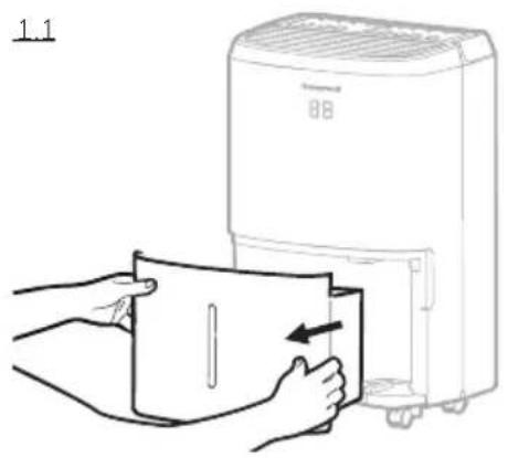
1. Draining water collected in the Water Tank
The condensed water can be collected directly into the water tank. When the water tank is full, the dehumidifier will automatically shut OFF and the 📋 indicator will illuminate on the control panel followed by a beeping sound.
IMPORTANT: Do not move the dehumidifier when the Water Tank is full as it will be heavy and can cause water spillage.
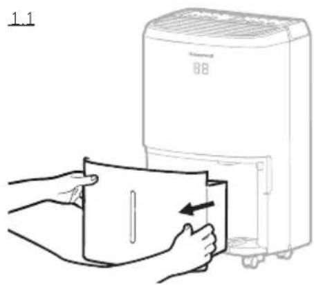
1.1 Locate the water tank at the front of the dehumidifier. Gently pull the water tank out.
1.2 Grip the handle inside the water tank and carry the water tank to a sink to empty.
1.3 Replace the empty water tank back into the front of the dehumidifier. Please make sure that the tank is properly positioned. The safety feature ensures that any misalignment of the tank and the unit will prevent the unit from turning back on.
IMPORTANT: Improper alignment or positioning of the water tank will cause the unit to pause operation, the warning light on top of the dehumidifier will illuminate followed by a beeping sound, until the water tank is fitted properly.
NOTE: There is a Foam Float inside the water tank that senses the water level to automatically stop dehumidification when the water tank is full. Make sure the Foam Float is positioned correctly inside the water tank by ensuring it lies level with the top edge of the water tank.
DO NOT REMOVE THIS FOAM FLOAT.

natural_image
Line drawing of hands holding a clipboard with a tool, no text or symbols present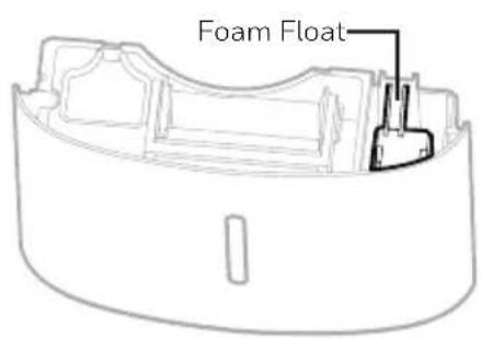
DRAINING THE WATER (CONTINUED)
2. Continuous Water Drainage – Using a Continuous Water Drain Tube
A continuous water drainage tube is included with this unit. To activate the continuous water draining function, you will require a suitable water drain (e.g. sink or drain hole at floor level) near the dehumidifier.
Continuous Water Drain Tube 3.28 ft. (1 m)
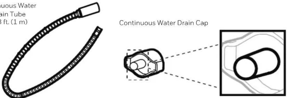
NOTE: The Continuous Drain Tube and Continuous Drain Cap come pre-installed.
2.1 Locate the drain outlet at the back of the unit. Unscrew and remove the Direct Drain Cap. Insert and screw the Continuous Water Drain Tube into the Direct Drain Outlet.
DRAINING THE WATER (CONTINUED)
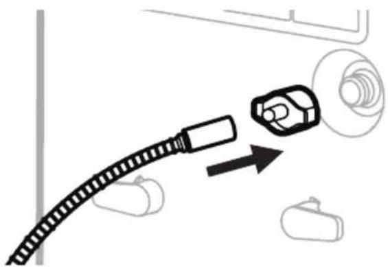
2.2 If there are leaks, the Continuous Water Drain Tube and Cap may have loosened and may not be connected properly. Disconnect, replace and tighten again.
natural_image
Diagram showing a cable connector with a magnified inset of a car body and a separate vehicle (no text or symbols)2.3 Position the other end of the Continuous Water Drain Tube in the sink or drain. Make sure the tube is not bent or kinked which might stop the water flow. Make sure the tube is secured over the drain and will not fall out of place causing unwanted water spillage.
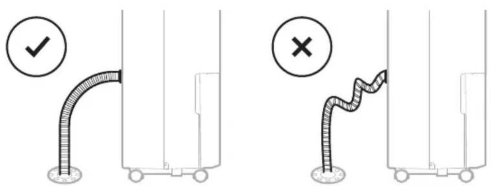
IMPORTANT: Make sure water can flow down the Continuous Water Drain Tube by keeping the tube angled down and free of bends or kinks.
IMPORTANT: If the unit is placed on uneven ground, or the Drain Tube is installed incorrectly, the water may fill the water tank and stop running. Please check whether the ground is uneven and reinstall the Drain Tube.
CLEANING & MAINTENANCE
WARNING: Always switch OFF the dehumidifier and unplug it from the electrical outlet before attempting any cleaning or maintenance of this product.
Appliance Maintenance:
- Switch OFF the appliance before disconnecting the power supply.
- Only use a soft cloth to clean the appliance.
Dust Filter Maintenance:
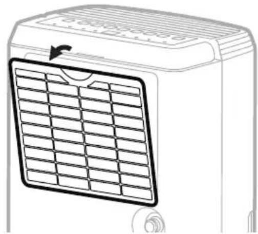
The Dust Filter located at the back of the unit helps to remove dust particles from the air. A dirty filter clogged by dust particles can reduce the efficiency of the dehumidifier. For optimum dehumidification, it is recommended to clean the dust filter every 2 weeks:
- Switch off and unplug the dehumidifier from the electrical outlet.
- Carefully pull out the dust filter from the dehumidifier.
- Rinse the dust filter under running water, or vacuum away the dust with a vacuum cleaner.
- After cleaning the dust filter, dry in a cool, shaded place, then carefully reinstall into the unit.
natural_image
Line drawing of a portable air conditioner unit with a grid-patterned panel and ventilation grille (no text or symbols)End of Season Storage & Maintenance:
If the appliance will not be used for an extended period of time:
- Switch OFF the unit and unplug from the electrical power outlet.
- Empty the water tank and let it dry. If your dehumidifier is connected to the continuous drain hose, you must disconnect the hose, dry and then replace the drain cap back into the drain outlet.
- Remove the air filter and clean with water. Let the air filter dry and reinstall back into the unit.
• Make sure all parts of the dehumidifier and accessories are dry before storage. - Cover the dehumidifier with a cloth/ plastic bag before storage, to protect the surface from dust and scratches.
- It is recommended to coil the power cord and store it off the floor to ensure it is protected from bends and kinks.
- Store the unit upright in a dry location, away from direct sunlight.
The following troubleshooting guide addresses the most common problems. If problems persist, call customer service.
| PROBLEM POSSIBLE CAUSE SOLUTION | ||
| Dehumidifier does not start | No electricity. Check for power. | |
| The power cord is not properly plugged in. | Remove and reconnect the power cord. | |
| The safety switch activated on the electrical plug. | Reset the safety switch and wait for 3 minutes to pass. Contact customer service if problem persists. | |
| The water tank is not in the correct position. | Position the water tank correctly into the unit. Unit will not operate until the water tank is secure in place. | |
| Unit runs but the humidity level does not decrease | The humidity level setting is too high. | Decrease the humidity level setting. |
| A door or window is open, letting in new moisture. | Make sure all windows or doors to the outside are closed and tightly sealed. | |
| There are other sources of humidity in the room (e.g. boiling water in pot). | Switch on the dehumidifier when these sources are not present. | |
| The temperature in the room is too low. | The dehumidifier is designed to operate between 41°F (5°C) and 89°F (32°C). Moisture removal is greatly reduced if room temperatures exceed this temperature range. | |
| The dust filter is dirty/ blocked. | Clean the dust filter. | |
| Air outlet or intake is blocked. | Remove blockage. | |
| Unit runs but the humidity level does not decrease | Insufficient time for the dehumidifier to remove moisture. | After initial installation, allow 24 hours to maintain desired dryness. |
| Dehumidifier runs constantly/does not stop | Area to be dehumidified is too large. | The capacity of your dehumidifier may not be adequate for the room it is used in. It is recommended to add an extra dehumidifier for large areas. |
| A door or window is open, letting in new moisture. | Make sure all windows or doors to the outside are closed and tightly sealed. | |
| Water Tank Full is illuminated and the unit is beeping | The water tank is full. Empty the water tank. | |
| The water tank is not in the correct position. | Position the water tank correctly into the unit. Unit will not operate until the water tank is secure in place. | |
| The unit is blowing cold air out of the top vent | The purpose of the top air vent is to distribute air into the room. | The temperature of the air from the vent depends on the room environment and other factors. It can fluctuate and this is normal. No action required. |
| Frost appears on the coils | Dehumidifier has been recently turned on in low room temperatures (usually below 41°F (5°C)). | This is normal. Frost will disappear in an hour or so after the dehumidifier is switched OFF. |
| Connected the continuous drain but the water condensation is not draining out the tube | Some floors may have an uneven surface which may affect the continuous drainage function | Raise the front of the Dehumidifier 1⁄2 to 1 inch (1.27 cm to 2.54 cm) from the floor. The water condensation will drain out the back hose and not into the bucket. |
TROUBLESHOOTING GUIDE (CONTINUED)
| PROBLEM POSSIBLE CAUSE SOLUTION | ||
| Water on the floor | The garden hose/ drain hose may be loose. | Check the connections between the hose and the drain outlet on the unit. See Continuous Water Drainage section. |
| You intended to use the water tank to collect water but the continuous drain hose is still connected. | Disconnect the hose and replace the rubber stopper and drain cap if using the water tank to collect water. See Continuous Water Drainage section. | |
| Noise Fan is working. | Wind from the fan can create sounds during operation. This is a normal sound. | |
CHOIX DE L'EMPLACEMENT - IMPORTANT (SUITE)
flowchart
graph TD
    A["16"] --> B[" "]
    A --> C["x2"]

natural_image
Simple line drawing of a coiled cable and connector (no text or symbols)natural_image
Diagram showing three cylindrical objects with arrows indicating movement or flow, enclosed in a rectangular frame (no text or symbols)natural_image
Diagram showing two cylindrical objects moving in a container with directional arrows indicating movement (no text or symbols)natural_image
Pure diagram of two identical mechanical components with mounting brackets and a circular symbol, no text or labels present.natural_image
Line drawing of hands holding a device with a clip, no text or symbols present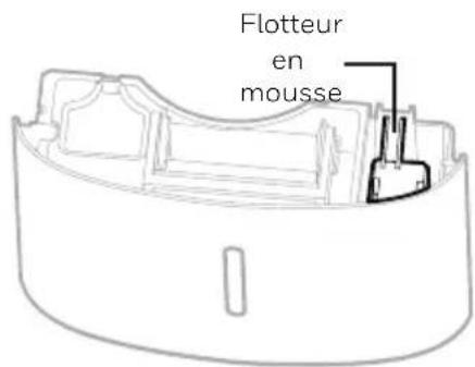
natural_image
Diagram showing a cable being inserted into a car component with an arrow indicating direction (no text or symbols)natural_image
Line drawing of a portable air conditioner unit with grid-patterned panel and ventilation slots (no text or symbols)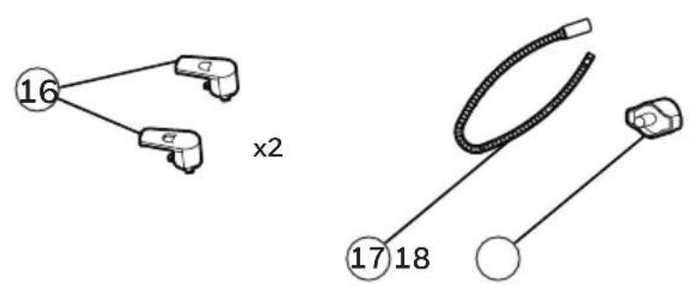
natural_image
Diagram showing two cylindrical objects with directional arrows inside a container, no text or symbols presentnatural_image
Diagram showing two cylindrical objects moving in a container with directional arrows indicating movement (no text or symbols)natural_image
Pure diagram of two labeled mechanical components (D) with mounting brackets, no text or symbols presentnatural_image
Line drawing of hands inserting a card into a portable air purifier (no text or symbols)
natural_image
Line drawing of hands holding a clipboard with a tool, no text or symbols present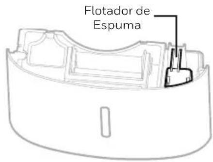
natural_image
Diagram showing a cable connector with a magnified inset of a car body and a separate device (no text or symbols)natural_image
Line drawing of a portable air conditioner unit with grid panel and ventilation slots (no text or symbols)SELECTEER EEN PLAATS - BELANGRIJK (VERVOLG)

flowchart
graph TD
    A["16"] --> B["x2"]
    A --> C["x2"]

natural_image
Simple line drawing of a coiled cable and connector (no text or symbols)natural_image
Diagram showing three cylindrical objects with arrows indicating movement or flow, enclosed in a rectangular frame (no text or symbols)natural_image
Diagram showing two cylindrical objects moving in a container with directional arrows indicating movement (no text or symbols)natural_image
Pure diagram of two identical mechanical components with mounting brackets and a circular symbol, no text or labels present.HET AFVOEREN VAN HET WATER

natural_image
Line drawing of hands holding a briefcase with a clip, no text or symbols present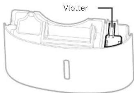
HET AFVOEREN VAN HET WATER (VERVOLG)
natural_image
Diagram showing a cable connector with a magnified inset of a device (no text or symbols)natural_image
Line drawing of a portable air conditioner unit with grid panel and ventilation slots (no text or symbols)
flowchart
graph TD
    A["16"] --> B[" "]
    A --> C["x2"]

natural_image
Simple line drawing of a coiled cable and connector (no text or symbols)natural_image
Diagram showing three cylindrical objects with arrows indicating movement or flow, enclosed in a rectangular frame (no text or symbols)natural_image
Diagram showing two cylindrical objects moving in a container with directional arrows indicating movement (no text or symbols)natural_image
Pure diagram of two identical mechanical components with mounting brackets and a circular symbol, no text or labels present.natural_image
Line drawing of hands holding a rectangular object with a clip, no text or symbols present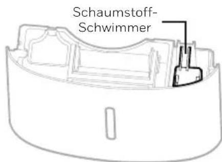
natural_image
Diagram showing a cable being inserted into a car component with an arrow indicating direction (no text or symbols)natural_image
Line drawing of a portable air conditioner unit with grid-patterned panel and ventilation slots (no text or symbols)SCELTA DELLA POSTAZIONE - IMPORTANTE (CONTINUA)

flowchart
graph TD
    A["16"] --> B["x2"]
    A --> C["x2"]

natural_image
Simple line drawing of a coiled cable and connector (no text or symbols)natural_image
Diagram showing three cylindrical objects with arrows indicating movement or flow, enclosed in a rectangular frame (no text or symbols)natural_image
Diagram showing two cylindrical objects moving in a container with directional arrows indicating movement (no text or symbols)natural_image
Pure diagram of two identical mechanical components with mounting brackets and a circular symbol, no text or labels present.NOTE: Before setting the Timer control, make sure there is power to the unit.
Timer Auto-Off:
natural_image
Line drawing of hands inserting a card into a portable air conditioner unit (no text or symbols)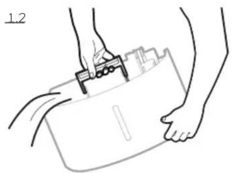
natural_image
Line drawing of hands holding a clipboard with a clip, no text or symbols present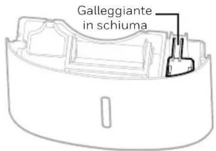
DRENAGGIO DELL'ACQUA (CONTINUA)
NOTE: The Continuous Drain Tube and Continuous Drain Cap come pre-installed.
natural_image
Diagram showing a cable connector with a magnified inset of a car body and a separate vehicle (no text or symbols)natural_image
Line drawing of a small air conditioner unit with a grid-patterned panel and ventilation grille (no text or symbols)ATT VÄLJA EN PLACERING - VIKTIGT (FORTSÄTTNING)

flowchart
graph TD
    A["16"] --> B[" "]
    A --> C["x2"]
natural_image
Simple line drawing of a coiled cable and connector (no text or symbols)natural_image
Diagram showing two cylindrical objects with arrows indicating movement or flow, enclosed in a rectangular frame (no text or symbols)Punkt 2: Rotera medurs 45 grader.
natural_image
Diagram showing two cylindrical objects moving in a container with directional arrows indicating movement (no text or symbols)natural_image
Pure diagram of a mechanical or electrical component with two labeled ports (C and D) and connection points, no text or symbols present.natural_image
Line drawing of hands holding a briefcase with a clip, no text or symbols present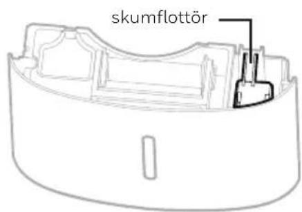
VATTENDRÄNERING (FORTSÄTTNING)
natural_image
Diagram showing a cable connector with a magnified view of a car body and a gear-like component, no text or symbols present.natural_image
Line drawing of a small air conditioner unit with a grid-patterned panel and ventilation grille (no text or symbols)VALG AF PLACERING - VIGTIGT (FORTSAT)

flowchart
graph TD
    A["16"] --> B["x2"]
    A --> C["x2"]

natural_image
Simple line drawing of a coiled cable and connector (no text or symbols)1) Kontrolpanel 10) Luftafgangsventilation på affugter
2) Håndtag 11) Vaskbart støvfilter
3) LED-display 12) Direkte aftapningsafløb
4) Beskyttelsesskærm 13) Direkte aftapningsdæksel
5) Håndtag på vandbeholder 14) Monteringshuller til ledningsopruller
6) Skumflyder 15) Ledning og stik
7) Vandbeholder 16) Ledningsopruller
8) Vandniveauindikator 17) Vedvarende vandaftapningsslange
9) Styrehjul 18) Vedvarende vandaftapningsdæksel
INSTALLER LEDNINGSOPRULLER
natural_image
Diagram showing three cylindrical objects with arrows indicating movement or flow, enclosed in a rectangular frame (no text or symbols)Trin 2: Drej 45 grader med uret.

natural_image
Diagram showing two cylindrical objects moving in a container with directional arrows indicating movement (no text or symbols)natural_image
Pure diagram of two identical mechanical components with mounting brackets and a circular symbol, no text or labels present.VIGTIGT: Do not move the dehumidifier when the Water Tank is full as it will be heavy and can cause water spillage.
natural_image
Line drawing of hands holding a device next to a portable air purifier (no text or symbols)
natural_image
Line drawing of hands holding a clipboard with a clip, no text or symbols present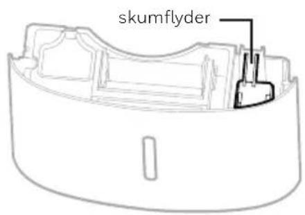
UDT∅MNING AF VAND (FORTSAT)
UDT∅MNING AF VAND (FORTSAT)
natural_image
Diagram showing a cable connector with a magnified view of a car body and a gear-like component, no text or symbols present.natural_image
Line drawing of a small air conditioner unit with a grid-patterned panel and ventilation slots (no text or symbols)End of Season Storage & Maintenance:
If the appliance will not be used for an extended period of time:
SIJAINNIN VALINTA - TÄRKEÄÄ (JATKUU)
natural_image
Diagram showing three cylindrical objects with arrows indicating movement or flow, enclosed in a rectangular frame (no text or symbols)natural_image
Diagram showing two cylindrical objects moving in a container with directional arrows indicating movement (no text or symbols)natural_image
Pure diagram of two identical mechanical components with mounting brackets and a circular symbol, no text or labels present.natural_image
Diagram showing a cable connector with a magnified inset of a car body and a separate vehicle (no text or symbols)natural_image
Line drawing of a portable air conditioner unit with grid-patterned panel and ventilation slots (no text or symbols)WYBÓR MIEJSCA – WAŻNE
WYBÓR MIEJSCA – WAŻNE (KONTYNUACJA)
NIE USUWAĆ TEGO PŁYWAKA PIANKOWEGO.

flowchart
graph TD
    A["16"] --> B["x2"]
    A --> C["x2"]

natural_image
Simple line drawing of a coiled cable and connector (no text or symbols)natural_image
Diagram showing three cylindrical objects with arrows indicating movement or flow, enclosed in a rectangular frame (no text or symbols)natural_image
Diagram showing two cylindrical objects moving in a container with directional arrows indicating movement (no text or symbols)natural_image
Pure diagram of two identical mechanical components with mounting brackets and a circular symbol, no text or labels present.NIE USUWAĆ TEGO PŁYWAKA PIANKOWEGO.
natural_image
Line drawing of hands inserting a card into a device labeled 'BB' (no text or symbols on the device itself)
natural_image
Line drawing of hands holding a briefcase with a clip, no text or symbols present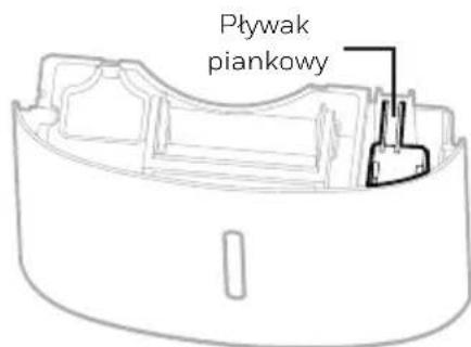
natural_image
Diagram showing a cable connector with a magnified inset of a car body and a separate vehicle (no text or symbols)natural_image
Line drawing of a portable air conditioner unit with grid-patterned panel and ventilation slots (no text or symbols)KONUM SEÇİMİ- ÖNEMLİ (DEVAM)

flowchart
graph TD
    A["16"] --> B["x2"]
    A --> C["x2"]

natural_image
Simple line drawing of a coiled cable and connector (no text or symbols)natural_image
Diagram showing three cylindrical objects with arrows indicating movement or flow, enclosed in a rectangular frame (no text or symbols)natural_image
Diagram showing two cylindrical objects moving in a container with directional arrows indicating movement (no text or symbols)natural_image
Pure diagram of two identical mechanical components with mounting brackets and a circular symbol, no text or labels present.natural_image
Line drawing of hands inserting a card into a refrigerator (no text or symbols)
natural_image
Line drawing of hands holding a clipboard with a tool, no text or symbols present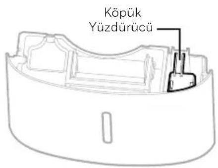
natural_image
Diagram showing a cable connector with an arrow pointing to a car component, surrounded by other devices (no text or symbols)natural_image
Line drawing of a portable air conditioner unit with grid-patterned panel and ventilation slots (no text or symbols)
flowchart
graph TD
    A["16"] --> B["x2"]
    A --> C["x2"]

natural_image
Simple line drawing of a coiled cable and connector (no text or symbols)natural_image
Diagram showing three cylindrical objects with arrows indicating movement or flow, enclosed in a rectangular frame (no text or symbols)natural_image
Diagram showing two cylindrical objects moving in a container with directional arrows indicating movement (no text or symbols)natural_image
Pure diagram of two identical mechanical components with mounting brackets and a circular symbol, no text or labels present.natural_image
Line drawing of hands inserting a card into a refrigerator (no text or symbols)
natural_image
Line drawing of hands holding a device with a clip, no text or symbols present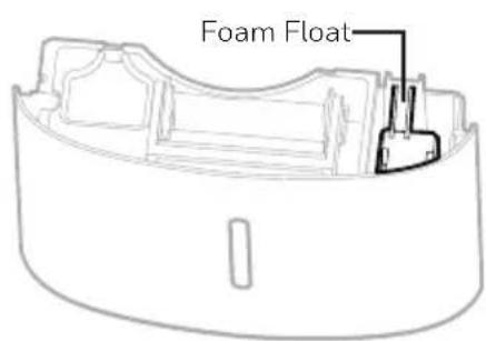
natural_image
Diagram showing a cable connector with a magnified inset of a car body and a separate vehicle (no text or symbols)natural_image
Line drawing of a small air conditioner unit with a grid-patterned panel and ventilation grille (no text or symbols)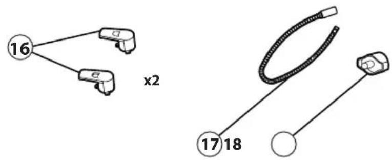
natural_image
Diagram showing three cylindrical objects with arrows indicating movement or flow, enclosed in a rectangular frame (no text or symbols)natural_image
Diagram showing two cylindrical objects moving in a container with directional arrows indicating movement (no text or symbols)natural_image
Pure diagram of two identical mechanical components with mounting brackets and a circular symbol, no text or labels present.natural_image
Illustration of hands inserting a card into a refrigerator (no text or symbols visible)
natural_image
Line drawing of hands using a tool to lift a rectangular object, no text or symbols present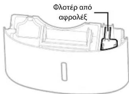
natural_image
Diagram showing a cable connector with a magnified inset of a device (no text or symbols)natural_image
Line drawing of an air conditioner unit with a grid-patterned panel and scroll (no text or symbols)LOKÁCIÓ KIVÁLASZTÁSA - FONTOS (FOLYTATÁS)

natural_image
Diagram showing three cylindrical objects with arrows indicating movement or flow, enclosed in a rectangular frame (no text or symbols)natural_image
Diagram showing two cylindrical objects moving in a container with directional arrows indicating movement (no text or symbols)natural_image
Pure diagram of two identical mechanical components with mounting brackets and a circular symbol, no text or labels present.natural_image
Line drawing of hands holding a clipboard with a tool, no text or symbols present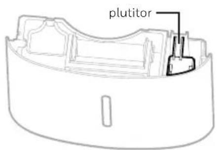
FOLYAMATOS VÍZELVEZETÉS - (FOLYTONOS)
natural_image
Diagram showing a cable connector with a magnified inset of a car body and a separate vehicle (no text or symbols)natural_image
Line drawing of a portable air conditioner unit with grid-patterned panel and ventilation slots (no text or symbols)ALEGEREA AMPLASĂRII – IMPORTANT (CONTINUARE)

flowchart
graph TD
    A["16"] --> B[" "]
    A --> C["x2"]

natural_image
Simple line drawing of a coiled cable and connector (no text or symbols)natural_image
Diagram showing three cylindrical objects with arrows indicating movement or flow, enclosed in a rectangular frame (no text or symbols)natural_image
Diagram showing two cylindrical objects moving in a container with directional arrows indicating movement (no text or symbols)natural_image
Pure diagram of two identical mechanical components with mounting brackets and a circular symbol, no text or labels present.natural_image
Line drawing of hands inserting a card into a portable device (no text or symbols)
natural_image
Line drawing of hands holding a clipboard with a tool, no text or symbols present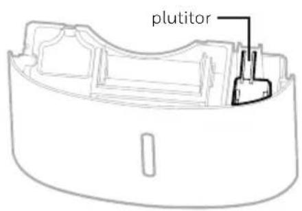
DRENAREA APEI (CONTINUARE)
natural_image
Diagram showing a cable connector with a magnified inset of a car body and a separate vehicle (no text or symbols)natural_image
Line drawing of a portable air conditioner unit with a grid-patterned panel and airflow direction arrow (no text or symbols)VÝBER UMIESTNENIA - DÔLEŽITÉ (FOLYTATÁS)

flowchart
graph TD
    A["16"] --> B["x2"]
    A --> C["x2"]

natural_image
Simple line drawing of a coiled cable and connector (no text or symbols)natural_image
Diagram showing three cylindrical objects with arrows indicating movement or flow, enclosed in a rectangular frame (no text or symbols)natural_image
Diagram showing two cylindrical objects moving in a container with directional arrows indicating movement (no text or symbols)natural_image
Pure diagram of two identical mechanical components with mounting brackets and a circular symbol, no text or labels present.When the Water Tank is full, the 📋 indicator will be illuminated. The unit will beep for 3 seconds. The compressor will shut off, and the fan will stop for a few minutes. To switch off the 📋 indicator light, empty the water tank and when replacing it ensure the tank is secured properly in place.
natural_image
Line drawing of hands inserting a card into a device labeled '8B' (no text or symbols on the device itself)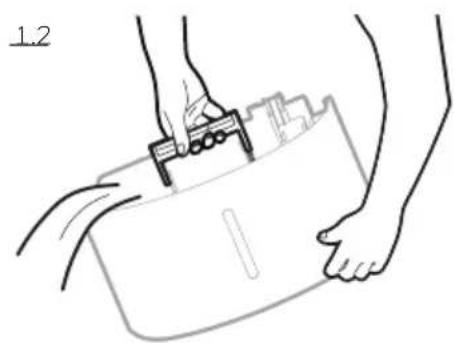
natural_image
Line drawing of hands holding a device with a clip, no text or symbols present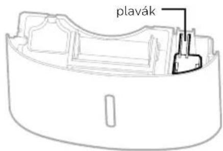
ODVODNENIE (FOLYTATÁS)
natural_image
Diagram showing a cable connector with a magnified inset of a car body and a separate vehicle (no text or symbols)natural_image
Line drawing of a portable air conditioner unit with grid-patterned panel and ventilation slots (no text or symbols)VÝBĚR STANOVIŠTĚ – DŮLEŽITÉ (POKRAČOVÁNÍ)
natural_image
Diagram showing three cylindrical objects with arrows indicating movement or flow, enclosed in a rectangular frame (no text or symbols)natural_image
Diagram showing two cylindrical objects moving in a container with directional arrows indicating movement (no text or symbols)natural_image
Pure diagram of a mechanical or electrical component with two labeled ports (D) and a base, without any text, numbers, or symbols.natural_image
Line drawing of hands holding a clipboard with a clip, no text or symbols present